
Improving the energy efficiency of the air-lift installation with a limited immersion depth of the mixer
Content
- Introduction
- 1. General Airlift Information
- 2. Airlift hydraulic circuit
- 3. Emergency Service
- 4. Airlift physical workflow model
- List of sources
Introduction
In the coal industry, as in other sectors of the national economy, there is a desire to mechanize all the main and auxiliary processes, where possible, in order to increase labor productivity, reduce production costs, reduce material consumption and energy costs, improve working conditions and improve safety and also, if possible, the exclusion of heavy unskilled labor.
Nowadays, more and more attention is paid to the mechanization of auxiliary processes, because they are mechanized almost 2 times less than the main ones. Of the auxiliary processes in the coal industry, the specific volume falls on the purification of sumps, water collectors, previous water tanks, mine wells and other similar objects, as well as on the pumping of contaminated water from sinking faces and on the cleaning of various sumps in processing plants.
Untimely cleaning of sumps of trunks, water collectors and receiving wells from solid leads to flooding of mine workings, which violates the normal rhythm of mines and leads to significant costs of material and labor resources.
The most progressive and relevant to modern requirements are installations with hydro-elevator (water-jet) devices and airlifts. With these purification methods, they are combined into one process of purification and pumping of water. The main equipment that provides cleaning with the new technology is a hydraulic elevator or airlift. These devices do not have rotational parts that move, are simple to manufacture, have a small mass and dimensions, their use eliminates the constant presence of service personnel in sumps, provides high pumping reliability in the conditions of blockages of devices with large volumes of solid and increases labor productivity in comparison with mechanical methods . These qualities at low capital and operating costs and high flow rate provide reliable and durable operation in difficult and compressed underground conditions. From studies conducted in NDIGM them. M. M. Fedorov revealed that these shortcomings are eliminated using two- and sometimes three-stage installation schemes.
1. General Airlift Information
One of the areas of technological progress in transport is the development of pipeline transport. The most promising is hydraulic transport, in which streams of water or a mixture carry loose materials through pipes or are transported by a supercharger into a homogeneous environment. Due to the well-known advantages of these types of transport are used when moving: minerals (coal, sand, gravel, oil, soluble salts, and much more) from the place of extraction to the consumer; processing plant waste; ash and slag of thermal power plants in dumps; waste rock to the place of storage, etc. Many hydrotransport schemes have vertical and inclined sections, for example, the lifting of solid material from underground workings or from the bottom of various water bodies during mining; rise of a dropping liquid (water, oil, etc.) to the day surface. As shown by theoretical and experimental studies of DonNTU and other scientific centers, as well as the operating experience of the hydraulic systems they created, it is sometimes enough to completely use airlift installations.
The principle of airlift
(animation: 7 frames, 7 cycles of repetition, 124 kilobytes)
The processes that occur in the riser airlifts are a set of interconnected processes of hydrodynamics, heat transfer and physico-chemical interaction of air with impurities. Each process is complex, which complicates its description. A theory has not yet been created that describes at least approximately the processes of motion of two-phase flows, therefore, the study of these processes and their laws goes along the path of piling up experimental material. For a theoretical description of the process of movement of a water-air mixture in pipes, it is necessary to know the structure of the flow under different operating conditions of the air-lift installation.
For supplying water from deep wells, pneumatic lifts or airlifts have been used; they are also convenient for supplying acids and other chemical liquids and mixtures with solid particles (pulps). The principle of operation is that compressed air from the compressor is supplied through the nozzle to the riser enclosed in the casing, through the nozzle. This creates a mixture of air and water. The movement of the air-water mixture up occurs due to the lifting action of air bubbles, which are ahead of the movement of water, slipping through the stream that moves, capturing water with it.
The process of moving a gas-liquid mixture in an airlift's lifting pipe is complex, the parameters are used to describe it: the average flow rate, its density, the ratio of volumes filled with liquid and gas, phase velocity and others. The flow regime or the structure of the gas-liquid flow also plays a significant role. For the normal operation of the airlift, some geometric immersion h of the mixer is necessary (the distance from the water level in the sump to the place where the compressed air enters the mixer), the value of which depends on the lift height H (the distance from the water level in the sump to the place where the pulp is drained from the air intake) of the hydraulic mixture and fluctuates from several meters to tens and hundreds of meters.
Figure 1.1. The hydraulic circuit of a full-scale experimental airlift installation is shown. It contains a mixer 1, a supply of compressed air, which is carried out through an air duct 2, a lifting pipe 3 Ø 0.15 m and a length of 15.21 m. The airlift installation was immersed using a metal tank 8. Using four drain valves 17, the required depth was maintained dives 0.76; 1.21; 1.52; and 2.23 m, corresponds to relative dives 0.05; 0.08; 0.1; 0.15. During the experiment, water was continuously supplied to the tank by pump 15, the supply of which was controlled by the valve 16. The remaining water from the tank was discharged through one of the valves 17 into the sump 19, which ensured the constant geometric immersion of the airlift mixer during the experiment. The airlift feed was measured by the volume-weight method, for which a volumetric tank 5 with a level indicator, volume units, a cargo dynamometer GD 7 and a stopwatch Z 6 served for counting the time for filling the volumetric tank. Volumetric tank volume W = 0.358 m. It is selected with the condition that its filling time in all operating modes of the installation would be at least 1-2 minutes. The source of compressed air was a TG-50-1.9 turbo-gas blower, in Figure 14, the consumption of compressed air in the airlift installation was regulated by a valve 12 installed on an air duct 2 Ø 0.15 m and a valve 13 that has an outlet through a noise muffler to the atmosphere.
2. Airlift hydraulic circuit
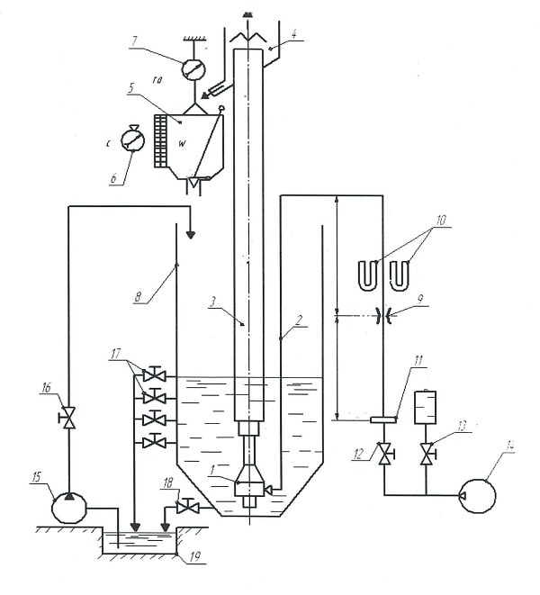
Figure 1.1 - Hydraulic diagram of a full-scale experimental airlift installation.
The measurement of compressed air costs was carried out using a normal diaphragm 8, with a diameter of 90 mm. The pressure drop across the diaphragm and the pressure in front of the diaphragm were measured, by analogy with the laboratory setup, using U-shaped monometers 10.
The hydraulic circuit of the laboratory airlift installation is shown in Fig. 1.2. In order to obtain more information about the processes that occur in the airlift when working with small absolute and relative dives, all of its main elements (supply and lift pipes, mixer) were made transparent (from plexiglass). The diameter of the lifting pipe 3 airlifts is 0.14 m, the length is 4.67 m.
To create an airlift immersion, a metal tank 6 was used. Water was supplied to the tank through a pipe Ø 0.0105 m using a pump 7. The immersion of the airlift mixer was controlled using a gauge glass 17 mounted on the tank.
As a source of compressed air, a turbo-gas blower (pos. 9) TG-50-1.9 with a maximum overpressure of 9×10⁻³ MPa was used. The regulation of the expenditure of compressed air, which enters the airlift through the air duct (pos. 2) Ø 0.105 m, was carried out using a valve 15 installed on the air duct and a valve 10 to discharge excess air into the atmosphere.
To measure the cost of compressed air in the airlift, a normal diaphragm 12, Ø 67.2 mm with annular chambers was used. The pressure drop across the diaphragm and the pressure in front of the diaphragm were measured using U-shaped monometers 13 filled with water and mercury, respectively.
The hydraulic circuit of the laboratory airlift installation is closed: the water that rises the airlift, after the air cooler 4 is sent to a triangular spillway 5, and then discharged into the tank.
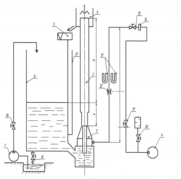
Figure 1.2 - Hydraulic diagram of a laboratory airlift installation.
3. Emergency Service
| No. p / p | Malfunctions | Cause | Remedy |
|---|---|---|---|
| 1. | During start-up, the airlift did not start working, air pressure 0.1-0.2 kgf / div | Suction pipe clogged due to poor flushing when stopped | Clean the suction pipe. Supply air to airlift mixer |
| 2. | During start-up, the airlift did not start working, the pressure in the mixer was 1 kgf / cm | Clogged mixer or riser | Rocking of the airlift by subsequent starts with a sharp air supply at the maximum water level in the sump |
| 3. | During normal operation, pulp is ejected from the air trap | The slurry pipe is clogged from the air separator to the consumer | Clean the slurry line |
| 4. | During start-up of the airlift and the working supercharger, air does not enter the airlift | Close gate valves or fuses | Repair valve |
Transition to work as a backup airlift:
- The scheme provides for the possibility of switching to work as a backup airlift.
- The backup airlift is started according to the
start airlift
. - Stop working airlift according to
stop airlift
.
The order of admission to the inspection, repair and testing of the air-lift installation:
- The admission to the inspection of the air-lift installation is carried out with the permission of the shift supervisor. During the inspection, it is allowed to record readings, revealed defects, interview service personnel for the operation of equipment.
- Repair airlift installation do outfits.
- Test the air-lift installation according to the approved program below.
- The order of conclusion in the repair of the air-lift installation.
- Permission for repairs to be made according to P.T.B.
- Go to the backup airlift installation according to the
transition to work as a backup airlift
- Ensure sturdy and reliable equipment
- To carry out an event regarding the conclusion of an airlift installation for repair
- Close and disassemble the email. Schemes, translate willow. manual drive of valves, close the circuit, hang out the posters
Do not open, people work.
- Hang up posters on a non-working installation! -
Work is here
; - To hang out posters on a working airlift installation! -
Caution - the equipment is working.
4. Airlift physical workflow model
The ring structure of many researchers are divided into a ring and a dispersed-ring. The annular structure is characterized in such a way that the liquid moves in the form of a film along the pipe (channel) wall, and the gas core with insignificant drop-shaped liquid inclusions occupies the central part. With a dispersed-ring structure, a significant number of related drip liquids are retained in the gas core. It is noted that a significant assignment of liquid to the gas core takes place in a high-speed annular flow. However, a quantitative criterion of significance or insignificance does not exist, including due to the lack of a reliable quantitative assessment of attribution. In addition, the existence of a ring structure without drip assignment seems problematic.
Based on the foregoing, in this work, by the ring structure of a water-air flow in a vertical airlift lifting pipe we mean one in which a liquid film of thickness z moves along the inner wall, and a gas with droplet and fluid inclusions close to them creates a flow core. Between the gas-liquid core of the stream and the liquid film, mass transfer takes place due to the attribution and deposition of droplets.
For water-air flows, dynamic (wave) assignment or stall and shock splash separation are shared. Dynamic assignment is carried out as a result of the breakdown of a part of the liquid from the crests of the large-scale waves that are obtained on the liquid film. Impact spray is caused by the dropping of secondary drops from the impact of droplets that settle from the core of the stream on the liquid film.
The dropping of the droplets is caused by turbulent pulsations and transverse forces in the gradient velocity field of the gas component.
Three modes of the film surface are distinguished: wave mode with large-scale waves, wave mode with ripples and smooth film mode. The friction between the film and the core of the flow is determined by the roughness
or structure of the wave surface of the liquid film, which is preferably formed by its thickness. A crisis of the hydraulic support is observed, when an increase in the gas flow rate leads to a decrease in the hydraulic support through a decrease in the rustiness
of the exposed film.
Separate the kelp and the turbulent regime of fluid movement in the film. The laminar regime is realized at Re <300: 400, and the turbulent regime at Re> 400, where the Reynolds number of the film is determined from the dependence.
It was shown in [32] that, in a developed turbulent regime (Re> 103), a liquid in a thin presented film is transported mainly in waves, that is, waves practically do not move relative to the film.
Compared to the shell, the ring structure is less studied and quantified by the theory of two-phase separate flow with a large number of assumptions and norms.
The question of accepted assumptions of hydrodynamic parameters when constructing conservation equations for an annular two-phase flow was considered in [11, 16, 32]. The created models of annular flows for gas-lift wells and steam-water flows in these installations are characterized by application conditions and cannot be unambiguously used for calculating the working process in a general production airlift.
The methodology of the spatio-temporal separation of the velocities of the components of the annular flow, by analogy with [11], is illustrated by a change in the diagrams of the velocities of air and water, which create a two-phase flow.
In the equations of continuity of motion and momentum of a water-air flow with a ring structure, hydrodynamic parameters (velocities, pressures, densities, etc.) are used, averaged over the time and cross section of the lifting pipe.
List of sources
- Эрлифтные установки: Учебное пособие / В. Г. Гейер, Л. Н. Козыряцкий, В. С. Пащенко, Я. К. Антонов – Донецк: ДПИ, 1982. – 64 с.
- Энциклопедия эрлифтов / Ф. А. Папаяни, Л. Н. Козыряцкий, В. С. Пащенко, А. П. Кононенко – М.: Информсвязьиздат, 1995. – 592 с.
- Данилов Е. И. Исследование и разработка эрлифта для гидромеханизированной очистки водоотливных емкостей: Дисс, …канд. Техн. Наук: 05.05.06 – Донецк: ДПИ, 1979. – 298 с.
- Мусияченко Е. В. Расчет и проектирование машин непрерывного транспорта (Электронный ресурс) – Электронные данные (13 Мб)
- Путилов В. Я., Путилов И. В. Расчет абазивного износа трубопроводов пневмотранспортных установок золы и угольной пыли ТЭС/Теплоэнергетика, №9, 2003 – с. 60-67
- Кононенко А. П. Ограничения в подаче эрлифта // Вестника Донбасской национальной академии строительства и архитектуры. Сборник научных трудов:
Технология, организация, механизация и геодезическое обеспечение строительства
. Выпуск 2005-7(55). Макеевка: ДНАСА – 2005. – С.71-81 - Папушин Ю. Л.
Илонакопители
, Сборник трудов кафедры ОПИ ДонНТУ. - Стифеев Ф. Ф. Разработка эрлифтов для подъема пульп повышенной плотности: Дисс … канд. Техн. Наук: 05.05.06 – Донецк: ДПИ, 1985 – 262 с.
- Куталадзе С. С., Стирикович М. А. Гидродинамика газожидкостных система. – М.: Энергия, 1976 – 296 с.
- Нигматуин Р. И. Динамика многофазных сред. Ч.И. – М.: Наука, гл. ред. физ. мат. лит., 1987 – 360с.
- Гриценко А. И., Клапчук О. В., Харченко Ю. А. Гидродинамика газожидкостных смесей в скважинах и трубопроводах. – М: Недра, 1994 – 238с.