
Content
- INTRODUCTION
- 1. ANALYSIS OF THE OBJECT OF MANAGEMENT
- 1.1 Basic design, technological and technical-operational characteristics and problems of the control object
- 1.2 Description of the movement of the ball along the inclined trough
- 1.3 Formalization of the control object and requirements for self-propelled guns
- 2. REVIEW AND ANALYSIS OF KNOWN DECISIONS ON AUTOMATION OF THE OBJECT
- 2.1 Analysis of existing control systems
- 2.2 Analysis of existing computer vision systems
- 2.3 Goals and objectives of development
- 3. DESIGN OF THE LABORATORY LAYOUT ACS
- 3.1 Justification of the accepted direction of solving the problem of work
- 3.2 Functional diagram of self-propelled guns
- 3.3 Selection and development of technical means of self-propelled guns
- 3.3.1 Microcontroller selection
- 3.3.2 Selecting a video camera
- 3.3.3 Servo selection
- 3.3.4 PC selection
- CONCLUSIONS
- LIST OF LINKS
INTRODUCTION
Designing, operating and improving automatic control systems, making optimal decisions and finding the necessary and correct way of automation are complex tasks that require qualified specialists in the field of control and system modeling. Obviously, to train highly qualified specialists who would have deep theoretical knowledge and practical skills in the field of electronics, automation, as well as in the field of telecommunication systems and networks, it is necessary to use fairly simple visual aids and models of automation systems in the educational process, which were would be made with the direct participation of students. Students work on such projects,
1. ANALYSIS OF THE OBJECT OF MANAGEMENT
1.1 Basic design, technological and technical-operational characteristics and problems of the control object
The proposed system, consisting of a ball and a gutter, is also called "Ball and Beam". Most often, this installation is found in most technical laboratories. This is due to the simplicity of the design and implementation of the automatic control system. This system allows you to cope with real problems such as horizontal stabilization of the aircraft during landing and turbulent air flow.
The Ball-Beam training and laboratory bench using a web camera directly consists of a ball with a radius of 20 mm, a steel rail 30 cm and a video camera located above the gutter in such a way that it captures it completely. The gutter itself is fixed from one end to a stationary rack, and the other through a lever to the gear of the servo shaft, which carries out the movement of the gutter. Figure 1.1 below shows the installation diagram.

Figure 1.1 - General view of the laboratory bench
The position of the ball on the trough is controlled by changing the angle of inclination of the trough itself. In this work, we used an algorithm for selecting an object in an image by the distribution of color gamut. This approach is quite simple and can be used to track an object whose color is different from the background. To highlight the ball, the background of the laboratory setup will be painted in one color, thereby highlighting the ball.
It is necessary to track the movement of the ball on the gutter and select it with some figure. To do this, take the following steps:
1) selection of pixels corresponding to the ball;
2) finding the contour of the ball;
3) the construction of a circle into which all points of the contour of the ball fall.
To change the tilt angle of the gutter, an executive mechanism (servo or stepper motor) is used, of high power, which is controlled on a computer through a microcontroller. A digital camera mounted on top of the gutter tracks the object on the gutter and transfers the pixel value to the computer where the ball coordinate is calculated in real time. And based on these coordinates, the angle is calculated at which the gutter should lean. The image is transferred to the PC.
The ball can be made to move along any trajectory and even stabilize it. This control method describes the principle of feedback control. The purpose of the system is to control and maintain the position of the ball at the desired control point and compensate for disturbances.
To describe the system, use the state space method. The non-linearity is negligible at small angles of deviation of the trench from the horizontal position, in this case, you can simply linearize the system. At large tilt angles, the nonlinearity becomes more significant. In this case, it is necessary to carry out the approximation more carefully.
1.2 Description of the movement of the ball along the inclined trough
To describe the motion of a ball, it is enough to know the law of motion of any of its points and the law of rotation of the body relative to this point.
We obtain the equations of motion of the ball under the following assumptions: a ball of mass m = 0.005 [kg] and a radius of R = 0.02 [m] rolls without slipping along two parallel guides of the trough, the distance between which is L = 0.015 [m], set
at an angle
![]() to the horizontal to distance
to the horizontal to distance
![]() from each other [2]. The ball is affected by the force of gravity
from each other [2]. The ball is affected by the force of gravity
![]() applied to the center of mass, resulting in
applied to the center of mass, resulting in
![]() two reaction forces from the side of the trench, perpendicular to the inclined plane formed by the guides, and passing through the center of mass of the ball, as well as the result
of
two reaction forces from the side of the trench, perpendicular to the inclined plane formed by the guides, and passing through the center of mass of the ball, as well as the result
of
![]() two rest friction forces [3], acting along the guides (Fig. 1.2).
two rest friction forces [3], acting along the guides (Fig. 1.2).

Figure 1.2 - Rolling the ball along an inclined trough
The motion of the ball is described by a system of two equations, based on [1] (the equation of motion of the center of mass and the equation of moments):
 (1.1)
(1.1)
where
![]() is the moment of inertia of the ball;
is the moment of inertia of the ball;
![]() - shoulder friction forces
- shoulder friction forces
![]() ;
;
![]() - angular acceleration associated with linear acceleration by the kinematic coupling equation
- angular acceleration associated with linear acceleration by the kinematic coupling equation
![]() .
.
Multiplying the first equation from (1.1) by
![]() and adding it to the second, taking into account
and adding it to the second, taking into account
![]() , we obtain the equation of motion of the ball along the plane in the absence of slippage in the form:
, we obtain the equation of motion of the ball along the plane in the absence of slippage in the form:
 (1.2)
(1.2)
Since in the case of the ball
![]() and
and
![]() [4], then equation (1.2) can be represented as:
[4], then equation (1.2) can be represented as:
 at
at
 . (1.3)
1.3 Formalization of the control object and requirements for self-propelled guns
Taking into account the above analysis of the features of the system under consideration, a diagram of the main ball balancing control channels [1] on the trough is obtained.
The main controlled variable characterizing the Ball and Beam setting is (Fig. 1.2) - the location (coordinate) of the ball .
Control actions, allowing to influence the considered controlled variable in the required manner (Fig. 1.2) - the angle of the servo drive.

Figure 1.3 - Representation of the installation “Ball and Beam” as a control object
The main disturbances affecting the controlled variable are variables (Fig. 1.2):
- friction force;
- external interference (wind, hand push of the ball, etc.);
- uneven trough;
- color of a sphere and external lighting.
The ball is detected on the rail and thus the angle of rotation of the actuator is set, the trench moves, and with it the control object begins to move.
2. REVIEW AND ANALYSIS OF KNOWN DECISIONS ON AUTOMATION OF THE OBJECT
2.1 Analysis of existing control systems
The considered Ball and Beam system using a web camera is a simple design for visual observation of all the rules of the classical theory of automatic control. Earlier, this system, only without the use of computer vision, was designed and demonstrated by many organizations.
Back in 1999, Hirsch built its Ball on Beam System. A photograph of the system is presented (Fig. 2.1). The system used an ultrasonic sensor to measure the position of the ball. The angle of rotation was measured using a potentiometer. The gearbox engine was driven by a powerful operational circuit amplifier. The system was controlled by a PD controller. Most analog systems use this type of configuration as Hirsch.

Figure 2.1 - The Ball on Beam System
Arroyo built a system called Ball on Balancing Beam in 2005 (Figure 2.2). The system used a resistive sensor to measure the position of the ball. The resistive position sensor acted as a wiper similar to a potentiometer, as a result of which the position of the ball was known. A DC motor with gear was used. The system was also controlled using the PD controller.

Figure 2.2 - The “Ball on Balancing Beam” system
This system was easy to build, and the PD controller was easy to develop. The disadvantage of the Ball on Balancing Beam system was that the gutter was made of acrylic, which is too fragile for a sudden blow and the very contact with the ball. In addition, the tilt angle of the gutter was not measured and not controlled. Although, the position of the ball was controlled by the PD controller. From a technical point of view, the system was not very reliable.
The Department of Electrical Engineering at Lakehead University built a system called “Ball and Beam Balancer” in 2006 (Figure 2.3). The system used a DC motor with an integrated gearbox, a resistive position sensor and a digital encoder. The system was controlled by the LQR controller.

Figure 2.3 - The Ball and Beam Balancer system
The Ball and Beam Balancer system had one input (motor voltage input) and two outputs (ball position and tilt angle). The system was very reliable because the state-space method with the LQR controller is good at controlling the MIMO system (multiple input, multiple output). The Ball and Beam Balancer was heavy because the gutter was made of aluminum, which is much heavier than acrylic
In parallel with Lakehead University, Quanser introduces its commercial product under the name “Ball and Beam Module” (Figure 2.4). The module consisted of a position sensor, made of resistive wires and a DC servomotor with a reduced gearbox. The system can be controlled by a PID controller or a state space controller. A relative small motor can be used for the system due to the shoulder effect.

Figure 2.4 - Quanser Ball and Beam Module System
Quanser also proposed a similar self-propelled ball with a ball not only on the gutter, but on a platform called 2DOF Ball Balancer. This implementation is presented in Fig.2.5.
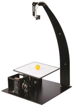
Figure 2.5 - The control system presented by the laboratory
Quanzer
This platform consists of a plate on which the ball should be located, two Quanzer laboratory servo drives that are connected to the sides of the plate, as well as a high-resolution camera. The plate can rotate in any direction. By controlling the position of the gears with a servo, you can adjust the position of the plate to balance the ball to the desired position. Using the software, you can set the trajectory of the ball using a microcontroller. From the point of view of management, this laboratory bench implements the principle of feedback control. This stand fully meets the purpose of this work. The disadvantage of this system is the price and paid software of Quanzer.
Based on the analysis of existing ball balancing systems on the gutter and on the platform, we made a choice of our own implementation of this stand, using the experience of previous developments and compiling them. The principle of feedback was chosen as the principle of control, since it is it that is most suitable for the implementation of the system. Since we need to adjust the angle of rotation of the servo based on the information received from the camera.
2.2 Analysis of existing computer vision systems
For a laboratory layout, existing computer vision algorithms should be analyzed. Currently, libraries have been proposed for monitoring objects using a video camera: OpenCV, PCL (Point Cloud Library) and JMyron. Each of these libraries has its own characteristics, its own algorithms. Let's consider each in turn.
OpenCV is a library of algorithms for computer vision, image processing and general purpose numerical algorithms. Mostly used within the framework of the C / C ++ language.
The object detection algorithm can be represented by a sequence of the following operations:
1. Getting a frame from the camera;
2. Convert images from RGB to HSV;
3. Passing through a mask of some color;
4. Calculation of the moments of the image.
The following is an example of an object detection using the OpenCV library.

Figure 2.6 - Detecting an object using OpenCV
As you can see from the figure, all objects around are discolored, and the camera sees only the object necessary for tracking, a certain color.
This library has a fairly complex software implementation in view of its writing in C / C ++. Its advantage is that it better describes the algorithm for highlighting the color of the desired object.
PCL (Point Cloud Library) - an open project that allows you to process images in two-and three-dimensional space. The PCL library contains high-class algorithms for object evaluation, surface reconstruction, 3D registration, model fitting and segmentation.
Here are examples of implementations of this library.
From fig. 2.7 we see that the PCL library is quite complex, since the detection takes place along three coordinate axes.
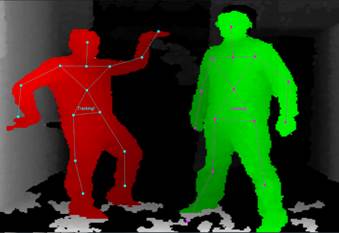
Figure 2.7 - Detection of 3D images using PCL
In fig. 2.8 depicts objects recognized by the PCL computer vision library. After analyzing the figure, we see that the point cloud very accurately recognizes visible objects. We can consider them in more detail in contrast to a flat image.

Figure 2.8 - Recognition of objects in 3D using PCL
The advantage of using PCL is that the object can be rotated, enlarged or reduced [5]. The cloud of points is much more accurate than an ordinary drawing and allows you to visually see the 3D-geometric model for further processing according to the necessary requirements. The disadvantage is the need to use more powerful, and therefore more expensive equipment.
JMyron computer vision library in the Processing programming language. This library has fairly simple algorithms for implementing computer vision, it is available in the public domain. In the programming language Processing, there is a library for interacting with the Arduino microcontroller, which is one of the main advantages. It consists in the fact that both Arduino and Processing have a fairly simple interface and program code similar to the Java programming language.
Here are some examples for tracking objects using the JMyron library.
Here are examples of implementations of this library.
In fig. 2.9 you can see that using the computer vision library JMyron can detect faces.

Figure 2.9 - Face detection using JMyron
However, there are several drawbacks to this library. One of the main ones is that this library is extremely sensitive to lighting. It requires the selection of the right room with the right lighting for the correct detection of the object.
Analyzing the existing computer vision libraries, the OpenCV library was chosen as part of this work, since it most closely meets the technical task of the work. Due to the accurate detection of the object on the gutter, you can get the exact value of the coordinate for its regulation and transmission to the actuator.
2.3 Goals and objectives of development
The above analysis of the features and characteristics of the Ball and Beam installation as a control object allows us to formulate the main goal of the project - to construct and control the real Ball and Beam system. In particular, the objectives are listed in the following:
- create a training and laboratory stand;
- identify and determine system parameters;
- implement various control algorithms;
- use the designed controllers to control the actual installation and compare the obtained characteristics.
To achieve this goal, you must perform the following tasks:
1) the design task is to choose a high-quality video camera, actuator and controller with the required accuracy class;
2) the task for management is to achieve speed and high sensitivity of the system, to achieve the desired results;
3) the information task is to provide continuous two-way communication between the control object and the control room (personal computer);
4) the task for the implementation of the protection functions is to choose reliable materials for creating the laboratory bench, as well as provide safe conditions for students to work with the bench.
3. DESIGN OF THE LABORATORY LAYOUT ACS
3.1 Justification of the accepted direction of solving the problem of work
To achieve this goal, it was decided to compile two Quanzer laboratory developments: Ball and Beam Module and 2DOF Ball Balancer. It is necessary to implement a training and laboratory stand, which should consist of: a gutter on which the ball will move, servos that will tilt the rail, depending on the coordinate of the ball on it and a video camera that will fix the ball on the gutter. It is important that the contact point with the servo arm is aligned with the fixed point of the secured trough. The servo must be installed in the middle position (90 degrees), and its height should be adjusted so that the shoulder is in a horizontal position when the gutter is in a horizontal position. The webcam should be positioned so that it looks exactly at the center of the gutter and captures its entire length. In order to make the detection of the ball easier, it is necessary to create a strong contrast between the external background of the laboratory stand and the ball. The OpenCV library in the C ++ programming language was chosen as the computer vision algorithm.
3.2 Functional diagram of self-propelled guns
The functional diagram of the installation is shown in Fig. 3.1:

Figure 3.1 - Functional diagram of an automatic control system
We describe each of the components of the system.
The webcam captures the image in real time and transfers it to a personal computer.
The personal computer processes the image transmitted from the web camera. It also implements the computer vision algorithm and the necessary regulators for operation. From the camera, the computer receives the image as a set of pixels. The computer receives one coordinate, the second is a constant, since the ball moves in one direction. Next, a crosshair is created, the coordinates of which calculate the center of the ball on the gutter with an accuracy of units of pixels. Based on the received coordinates of the object on the plane, the PC calculates the angle by which the drive must turn in order to fulfill the necessary. The angle value is transmitted to the Arduino microcontroller.
The Arduino microcontroller provides PC connectivity to the drive. Arduino Uno is connected to a PC via USB - UART. The angle calculated on the computer in the form of the corresponding code is transferred to the Arduino board, which in turn causes the drives to rotate this angle.
Actuator - a servo connected directly to the Arduino Uno board is required to tilt the gutter on which the ball is balanced.
The control object is a ball that moves along the gutter. The movement of the ball, as well as its position is recorded by a web-camera.
3.3 Selection and development of technical means of self-propelled guns
As hardware in this project, the following components were selected:
- Arduino Uno board - a microcontroller through which the servo drive is controlled;
- as an actuator, a servo drive is used, which tilt the gutter;
- a digital video camera that detects the ball on the balancing groove;
- a personal computer in which the control algorithm is implemented.
3.3.1 Microcontroller selection
In the modern world, a large number of microcontrollers from different manufacturers are offered. With the chosen implementation of the stand, you need a controller that has digital inputs / outputs, with an operating voltage of no more than 5V, since it is necessary to provide power to the controller from a PC. Also, the controller should be affordable and provide ease when programming it. Analyzing the microcontroller market, the Arduino Uno microcontroller was selected (Fig. 3.2).

Figure 3.2 - Appearance of the Arduino Uno board
With the chosen implementation of the training laboratory stand, the Arduino Uno board is the most optimal [9]. Arduino Uno is a device based on the ATmega328 microcontroller. It includes everything necessary for working with a microcontroller: 14 digital inputs / outputs (of which 6 can be used as PWM outputs), 6 analog inputs, a 16 MHz quartz resonator, a USB connector, a power connector, and an in-circuit programming connector ( ICSP) and reset button. To start working with the board, simply supply power from an AC / DC adapter or battery, or connect it to a computer using a USB cable.
Technical characteristics of Arduino Uno are given in table 3.1.
Table 3.1 - Specifications of the Arduino Uno
|
Technical parameter |
Parameter value |
|
Operating voltage, V |
5 |
|
Input voltage (recommended), V |
7 - 12 |
|
Input voltage (limit), V |
6 - 20 |
|
Digital I / O, pcs |
14 |
|
PWM I / O, pcs |
6 |
|
Analog inputs / outputs, pcs |
6 |
|
Maximum current of one output, mA |
20 |
|
Maximum output current 3.3V, mA |
fifty |
|
Flash - memory, KB |
32 |
|
Volatile memory (SRAM), KB |
2 |
|
Non-Volatile Memory (EEPROM), KB |
1 |
|
CPU frequency, MHz |
16 |
|
Length mm |
68.6 |
|
Width mm |
53,4 |
|
Weight g |
25 |
3.3.2 Selecting a video camera
The terms of reference for the project provides for the use of a video camera as an information-measuring system for determining the coordinates of the position of a ball on a plane. A camera is needed that has a sufficiently high resolution to capture the entire gutter in the frame. In the project we will use a high-resolution digital camera Gembird CAM100U (Fig. 3.3).

Figure 3.3 - Appearance of the Gembird CAM100U webcam
This camera is quite cheap and meets the requirements for solving the task. Technical characteristics of Gembird CAM100U [10] are given in table 3.2.
Table 3.2 - Technical characteristics of Gembird CAM100U
|
Technical parameter |
Parameter value |
|
Video resolution |
|
|
Focusing |
Manual |
|
Frame rate per second |
60 |
|
Lens, MP / interpolation up to, MP |
0.3 / 16 |
|
Interface |
USB 2.0 |
|
Weight g |
80 |
To assess the required speed of the ball coordinate measurement system, it is necessary to determine the possible minimum time the ball spends on an inclined plane. We write the following equations of motion of the ball along an inclined trough in the absence of slippage, based on [4]:
 (3.1)
(3.1)
where
![]() is the moment of inertia of the ball;
is the moment of inertia of the ball;
![]() - shoulder friction forces
- shoulder friction forces
![]() ;
;
![]() - angular acceleration associated with linear acceleration by the kinematic coupling equation
- angular acceleration associated with linear acceleration by the kinematic coupling equation
![]() .
.
Since in the case of the ball
![]() and
and
![]() [4], then equation (3.1) can be represented as:
[4], then equation (3.1) can be represented as:
 , at
, at
 , (3.2)
![]()
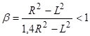
The condition is met:
![]() ,
,
![]()
Consequently,
![]() (3.3)
(3.3)
where
![]() is the angle of inclination of the plane;
is the angle of inclination of the plane;
g = 9.8 ms is the acceleration of gravity.
Assuming that the ball is located anywhere on the trench, which is inclined relative to the horizontal plane at an angle of 15 0 , based on (3.3) it is easy to calculate the time for which the ball, if its initial speed was zero. This time will be about 0.88 s.
Thus, in further calculations it should be taken as the minimum time the ball spends on the plane
![]() .
.
3.3.3 Servo selection
According to the functional diagram (3.1), a servo drive will be used as an actuator in the ACS being developed by moving the ball along an inclined trough.
When choosing servo drives, it is necessary to be guided by the very important characteristics of the servo drive, namely torque and turning speed.
The moment of force, or torque (
M ), is a vector physical quantity equal to the product of the radius vector (
![]() ) drawn from the axis of rotation to the point of application of force and the vector of this force (
F ). It characterizes the rotational action of a force on a solid.
) drawn from the axis of rotation to the point of application of force and the vector of this force (
F ). It characterizes the rotational action of a force on a solid.
![]() (3.4)
(3.4)
In the laboratory stand under development, a lever is provided, the length of which is
![]()
This characteristic shows how heavy the servo is able to keep at rest on the lever of a given length. The installation under development will not have a large load on the servo drive, as the mass of the ball is m
W = 0.005 [kg] and the mass of the trough itself m
W = 0.150 [kg]. The total load (
![]() ) that the servo will need to hold:
) that the servo will need to hold:
![]() (3.5)
(3.5)
The second characteristic that must be taken into account is the speed of rotation of the motor shaft. The servo speed is measured by the time interval that it takes the servo lever to rotate 60 °. This characteristic is more important in our case, because it is necessary to achieve the speed of the actuator (servo).
Another factor that needs to be considered is that the servo drive will be powered by the previously selected Arduino Uno microcontroller board, which has an operating voltage of 5V.
When analyzing the market for these mechanisms, the choice was made by Dsservo. The servo drive model DS3218 was selected (Fig. 3.4).

Figure 3.4 - the appearance of the servo drive Dsservo DS3218
Attention should be paid to the voltage supplied to the servo drive, if it exceeds the permissible, the gears will crank to a position exceeding the maximum, which will entail the inability of the mechanism to continue to move in reverse. A motor failure will not occur, but the mechanical part of the servo will be damaged.
Technical characteristics of the Dsservo DS3218 servo drive [11] are given in table 3.3.
Table 3.3 - Specifications of the Dsservo DS3218
|
Technical parameter |
Parameter value |
|
Operating voltage, V |
4.8 - 6.8 |
|
Angle of rotation, º |
0 - 180 |
|
Angular velocity |
0.16sec / 60º |
|
Starting moment, kg / cm |
19 |
|
Gear material |
metal |
|
Overall dimensions, mm |
40 × 20 × 40.5 |
|
Weight g |
65 |
The selected Dsservo DS3218 servomotor satisfies two main characteristics, with a starting torque of 19 kg / cm, which means that the servomotor holds the lever 1 cm in length in horizontal position, on the free end of which you can hang 19 kg, which
is much higher than previously calculated total load (
![]() ).
).
3.3.4 PC selection
We will use a personal computer as a system that implements a control algorithm. Computer software and system requirements:
- a processor with a frequency of 1.6 GHz and higher;
- at least 1 GB of RAM (when working on a virtual machine - at least 1.5 GB);
- A video card with support for a resolution of at least 1024 x 768 pixels;
- DirectX 9.0c or higher;
- Windows Vista, Windows 7, Windows 8, or Windows 10.
It is necessary to install the necessary software on the PC, in particular: VisualStudio 2012 and the OpenCV library (for programming the system itself), Arduino (for programming the microcontroller), WebCam driver.
CONCLUSIONS
Based on the results of the work, the following conclusions can be made.
1. The analysis of the control object - the movement of the ball along the gutter. The facts for the creation of an automation system are substantiated, the goals are formulated, the functions and tasks of the automation system of the training laboratory stand are described.
2. A concept has been made for the development of an automatic control system for balancing a ball on a trough for a laboratory bench. The paper shows that the most suitable for the implementation of self-propelled guns is a concept based on controlling the location of the ball on the gutter by changing the angle of rotation of the servo.
3. A selection of technical elements has been completed, allowing to fully realize the necessary functions of self-propelled guns. The Gembird CAM100U high-resolution digital camera was selected as an information-measuring device. Actuator - Servo Tower Pro MG90S. The Arduino Uno microcontroller board is selected for communication between the selected items and the PC.
4. A functional diagram of self-propelled guns was built, the main components of the system were identified, and their work was analyzed.
Thus, the selected set of technical means of self-propelled guns by moving the ball along an inclined trough using computer vision together with the developed algorithms allows to fully implement the necessary monitoring and control functions.
LIST OF LINKS
1. Левин М.Е., Рыженков В.М. Балансировка деталей и узлов. – М.: Машиностроение, 1986. – 248с.
2. Методы классической и современной теории автоматического управления: учебник в 5 томах., Т3: Синтез регуляторов систем автоматического управления. Под ред. Н.Д.Егупова.- М.: изд.МГТУ им. Н.Э.Баумана, 2004. -617c.
3. Лукас, В.А. Теория автоматического управления. / В. А.Лукас – М.: Недра, 1990. – 416 с.
4. Митин И.В. Задача № 125 Изучение движения шара по наклонному желобу. Лабораторный практикум по физике. Механика. Москва, 2011. [Электронный ресурс] URL: http://genphys.phys.msu.su/rus/lab/mech/Lab125_1.pdf (дата обращения: 15.11.2018).
5. Форсайт Д., Понс Ж. Компьютерное зрение. Современный подход. – М.: Вильямс, 2004 г. – 928 с.
6. Глория Буэно Гарсия. Обработка изображений с помощью OpenCV, 2016. – 210 c..
7. Филлипс, Ч. Системы управления с обратной связью. / Ч. Филлипс, Р. Харбор - М.: Лаборатория Базовых знаний.- 2001 - 616 с.
8. Двигатель постоянного тока [Электронный ресурс]: URL: http://el-mashin.narod.ru/text/53.html (дата обращения: 11.12.2018).
9. Микроконтроллерная плата. [Электронный ресурс] URL: http://arduino.on.kg/Arduino-UNO (дата обращения: 18.12.2018).
10. Информационно-измерительное устройство. [Электронный ресурс] URL: https://www.gembird.ua/0602071.html (дата обращения: 18.12.2018).
11. Сервопривод. [Электронный ресурс] URL:
http://www.zi-zi.ru/mechanism/motor-mg90s
(дата обращения: 18.12.2018).