
Abstract
This master's work is not completed yet. Final completion: June 2020. The full text of the work and materials on the topic can be obtained from the author or his head after this date.
Содержание
- Introduction
- Theme urgency
- 1. Analysis of existing MIMO technologiesy
- 2. Software implementation and analysis of the results of the model for evaluating noise immunity due to the singular decomposition of the correlation matrix
- 3. Implementation of a correction factor in the noise immunity assessment technique and the creation of a calculation algorithm
- Conclusion
- References
Introduction
In multibeam systems, the spacing of the antennas is an effective way to combat fading. One of the first methods was the separation of the antennas only at the reception – the system is SIMO (Single Input Multiple Output). It allows you to increase the immunity system without the use of spatial encoding techniques. Later with the development in the field of spatial–temporal lattice and block codes, was used the technique of dressing just for transfer, also called the technology a MISO (Multiple Input Single Output), as well as simultaneously receiving and transmitting – technology MIMO (Multiple Input Multiple Output). The most famous works in this area are the works of such foreign authors as: S. M. Alamouti (S. M. Alamouti), V. Taroh (V. Tarokh), Vol. brown (T. Brawn). Between the components of the coefficients of transmission channels of diversity reception almost always there is some dependence. This dependence is characterized for channels of reception coefficients of mutual correlation. Spatial correlation in MIMO and MISO systems has recently attracted great interest.
The MIMO system is inextricably linked to the spatial–temporal block coding (STBC). This coding is to transmit in each time point an independent data stream through each antenna. The most promising developing area is the representation of the MIMO system in the form of spatial subchannels obtained using the singular value decomposition of a matrix of transfer coefficients. These subchannels are referred to as private, as are used as weight vectors for spatial processing eigenvector matrix of transfer coefficients. These subchannels are parallel, so as to transmit independent data streams space-time block code.
While transmitting data, but the parallel subchannels of the MIMO system sennovsky throughput are investigated in the literature quite extensively. However, it is not considered approach to finding the throughput of MIMO N–order in channels with fading when accounting for multiple correlation.
Theme urgency
The aim of this work is to improve the methodology for assessing the noise immunity of the MIMO system based on the singular decomposition of the correlation matrix by introducing into it a correction factor taking into account the density of urban development.
The introduction of a correction factor, which takes into account the density of urban development in the method for determining noise immunity due to the singular decomposition of the channel matrix, is a scientific novelty.
The relevance of this work in obtaining a higher energy gain.
1. Analysis of existing MIMO technologiesy
MIMO system without feedback
In a non–feedback system (Figure 1.1), the total transmitter power P0 is evenly divided by M transmit antennas and transmitted through the channel, subjected to multiplicative amplitude and phase distortions, which are described by the H matrix, and the additive effect of white Gaussian noise Z.
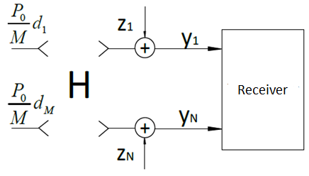
Figure 1.1 – Diagram of the MIMO system without feedback
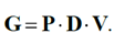
The elements of the matrix H are the complex factors that account for the fading in the channel from m–th (m = 1, 2,…, M) transmit antenna to the n–Oh (n = 1, 2,…, N) reception, the amplitude and phase of which are random independent identically distributed values. In the works devoted to computer simulation of systems with the spacing of the antennas is to model the matrix H with the command in Matlab:
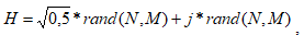
where N and M – a predetermined number of receiving and respectively transmitting antennas with a transmission coefficient of hmn; j – the imaginary unit such that j2=-1; rand – a function of generating independent and identically distributed random variables.
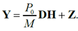
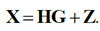
Then the matrix of the received signal after transmitting the code block:
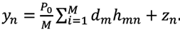
The signal at the input of each n–th receiving antenna is a linear combination of the signals from each m–th transmission:
MIMO feedback system
In the case where the transmitter has knowledge of channel matrix H, it is possible to carry out adaptive transmission on the parallel subchannels. Channel information can be obtained by transmitting pilot–signal. Known symbols are transmitted periodically, and the receiver retrieves and interpolates between them to estimate the channel for each transmitted useful symbol. The maximum number of subchannels is equal to the rank of the matrix H. In the case of Rayleigh channel, the probability of degeneration of the matrix H is negligible and its rank K is determined by the minimum number of transmit or receive antennas. The input unit of the spatial–temporary coder should consist of K parallel streams, and the output – of M streams (figure 1.2)
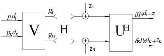
Figure 1.2 – Diagram of the MIMO system with feedback
Figure 1.2 shows the realization of data transmission on the parallel channels in the MIMO system assuming knowledge of the channel information matrix H on the transmitting side. Parallel streams of characters represented by a vector D = [d1, d2,…, dk]T are multiplied by a diagonal matrix of the distribution of power between the subchannels P = diag[p1, p2,…, pK] and the respective weighting vectors of the matrix V with dimension M ? K, obtained from singular value decomposition of the matrix H on the receiving side. The output signal of the matrix V can be represented by a vector G = [g1, g2,…, gM]T
After passing through the channel, the vector of signals received by the antennas is recorded:
Further, the signals at the receiver are multiplied by the matrix UH, with dimension N × K, the resulting singular value decomposition of H. the Signal at the receiver input will be written:
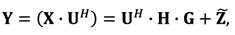
where Z=UH
In this case, firstly, the weight vectors of both the decoder and the encoder should be orthogonal to each other, i.e. no correlation of intrinsic noise should be ensured
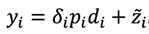
From this formula it is seen that in each i–th own subchannel is transmitted only i–th character. The received signal is described by the coefficients of the channel matrix hmn and the coefficients of transmission of each parallel channel δi in the form of K SISO systems.
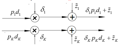
Figure 1.3 – the Equivalent circuit of a MIMO feedback
It can also be shown that the total energy of the channel matrix before and after the singular decomposition remains constant.
Based on the above described it can be argued that MIMO system can be represented as K independent channels. In this case the singular number shows the coefficient of transmission (high or low state of each parallel channel). Adjusting the power allocated to each subchannel depending on its state, determined by the matrix of Λ, it is possible to optimize various characteristics of the MIMO system.
2. Software implementation and analysis of the results of the model for evaluating noise immunity due to the singular decomposition of the correlation matrix
The peculiarity of this method is the selection and calculation of the eigenvalues of the subchannel due to the singular decomposition of the matrix.
To determine the noise immunity of the MIMO system with this honey, the following algorithm must be observed:
- It is required to enter the initial data, which are the number of transmitting M and receiving N antennas for the MIMO system, as well as the value of the correlation coefficient r.
- Then we proceed to the choice of the type of correlation matrix.
- Next, we calculate the generalized correlation matrix RMIMO.
- Now create an arbitrary matrix of transmission coefficients H by the formula:
- Then it is necessary to expand the correlation channel matrix.
- Subject to the singular decomposition of the channel matrix.
- For further work, the construction of the matrix KQ is required.
- Calculation of the eigenvalues ??of the matrix KQR and H.
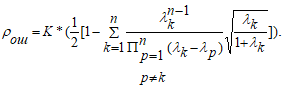
- And finally, we calculate the noise immunity using the formula:
where N and M are the number of receiving transmitting antennas, respectively.
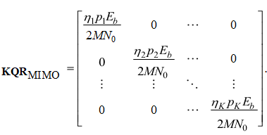
where K is the number of subchannels, F=K2
Using the above algorithm for calculating noise immunity, you can create a block diagram of a software calculation, which is given below.
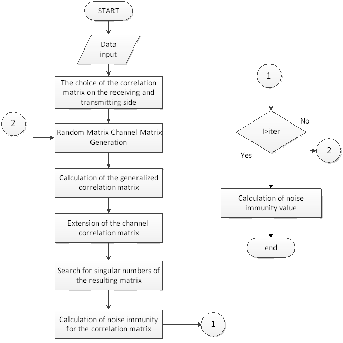
Figure 2.1 – the Block diagram of algorithm of calculation of noise immunity for MIMO system due to the singular decomposition of the channel matrix
![Figure 2.2 – the dependence of the error probability for heterogeneous channels Eb/N0 [dB] MIMO system of different orders and correlation coefficient r = 0.8 , when the binary phase modulation (BPSK)](images/graf.gif)
Figure 2.2 – the dependence of the error probability for heterogeneous channels Eb/N0 [dB] MIMO system of different orders and correlation coefficient r = 0.8 , when the binary phase modulation (BPSK)
(Animation: 7 frames, 7 repetition cycles, 53.3 kilobytes)
The result of determining noise immunity with ideal signal propagation is presented in Figure 2.2.
Also in this figure graphically illustrates a comparison of the noise immunity of a signal for systems with different number of transceiver–transmitting antennas when the value of correlation is 0.8.
Analyzing the data obtained from figure 2.2, it is clear that the error probability of 10-3 system MIMO transceiver with 3–transmitting antennas has an energy advantage of 4 dB compared to the MIMO system with 2 transceiver antennas. Setting the same value of the error probability, we get that from the MIMO receiver with 4–transmitting antennas energy advantage compared to the MIMO system with 2 transmitting antennas increases to 7 dB.
Implementation of a correction factor in the noise immunity assessment technique and the creation of a calculation algorithm
To improve the estimation of the noise immunity of the MIMO system due to the singular decomposition of the correlation matrix, we introduce a correction factor taking into account the urban density. Depending on the terrain, we select 2 formulas:
- Coefficient for small and medium cities
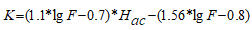
where the F – the frequency at which the system works; Hac – the height of the subscriber station, is usually taken 2 to 4 m.
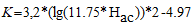
- Coefficient for large cities
Next, we introduce these coefficients into the basic formula for finding noise immunity. In the basic formula for calculating noise immunity takes the form
where K is the correction factor taking into account the building density.
Then we form an algorithm for calculating noise immunity based on the above.
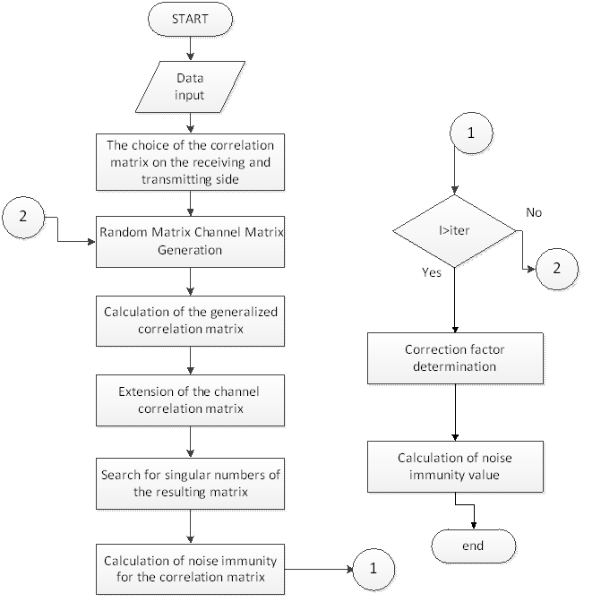
Figure 3.1 – Block diagram of algorithm of calculation of noise immunity for MIMO system due to the singular decomposition of the channel matrix with a correction factor.
To evaluate the obtained results, we introduce the correction factor data into yet another technique for estimating noise immunity without the singular decomposition of the channel matrix. To do this, we also create an algorithm by which the program will be created.
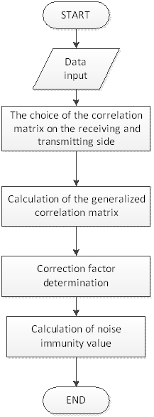
Figure 3.2–Block diagram of noise immunity calculation algorithm for MIMO system without singular decomposition of channel matrix with correction factor.
As a result, the predicted result is to obtain an estimate of the noise immunity of the signal for a particular area. Accordingly, since the ideal option was previously evaluated by comparing the result with it, we will see a decrease in the energy gain at the output, however, these results will be more correct.
Conclusion
In the course of the first part of the work, the planned goal was set, as well as the tasks put forward to achieve this goal.
Also, an analysis of MIMO systems with feedback and without feedback of the Nth order in channels with fading is taken into account when taking into account multiple correlation. In addition, an analysis of theoretical information on correlation in MIMO systems was carried out.
The second part was the method of assessment of immunity taken for a basis of work. Was written the algorithm for calculation of noise immunity, as well as the results obtained for the ideal location (no urban sprawl). These results are the following: when the probability of error of 0.001 (10-3) system MIMO3×3 is the energy gain in 4 dB on the system of the MIMO2×2. With the same probability have the MIMO4×4, the energy gain comparing with the system MIMO2×2 as much as 7 dB.
In the third part of the work, a coefficient is introduced that takes into account the density of urban development. A block diagram of the noise immunity calculation software product using this coefficient is also compiled.
References
- Янцен А. С. – Анализ помехоустойчивости систем радиосвязи, использующих технологию MIMO: диссертация кандидата технических наук – Новосибирск , 2017. – 157с.
- Лысяков Д. Н. – Анализ и синтез адаптивной обработки сигналов в системах радиосвязи с параллельной передачей информации по пространственным подканалам: дис. канд. физ. мат. наук. – Нижний Новгород , 2010. – 123с.
- Hanzo, Lajos, “MIMO–OFDM for LTE,WiFi, and WiMAX” : coherent versus non–coherent and cooperative turbo–transceivers / by L. Hanzo, J. Akhtman, L. Wang, M. Jiang. 2011 – 694 p.
- Носов В. И., Тимощук Р. С. Повышение помехоустойчивости канала с использованием 2М–пространственно–временного кодирования//Вестник СибГУТИ. 2010. №1. с.3–12.
- Тимощук Р. С., Носов В. И. Исследование пространственно–временной корреляционной модели для радиосистем с разносом передачи //Вестник СибГУТИ. 2012. №4. с.31–49.
- В. И. Носов, А. С. Янцен. Оценка спектральной эффективности и помехоустойчивости технологии MIMO при различном распределении мощности по параллельным подканалам // Телекоммуникации, 2017 г. –№ 2, – С.
- G. D. Durgin and T. S. Rappaport. A Basic Relationship Between Multipath Angular Spread and Narrowband Fading in a Wireless Channel//IEEE Electronics Letters, 1998, vol. 34, no. 25, p.2431–2432.
- A. van Zelst. A Compact Representation of Spatial Correlation in MIMO Radio Channels//Proc. of the 10th Mediterranean Electrotechnical Conf. (MELECON) 2000, vol. 3, May 2000, p.1218–1221.
- D. Shiu, G. J. Foschini, M. J. Gans, J. M. Kahn. Fading Correlation and Its Effect on the Capacity of Multielement Antenna Systems//IEEE Transaction On Communications, Vol. 48, No. 3, 2000., p.502–513.
- Шлома А. М., Бакулин М. Г., Крейнделин В. Б., Шумов А. П. Новые алгоритмы формирования и обработки сигналов в системах подвижной связи. –М. Горячая Линия – Телеком. 2008. –367c.