
Abstract
Content
- Introduction
- 1. The purpose and object of research development
- 2. Research and Development Overview
- 2.1 Overview of international sources
- 2.2 Overview of national sources
- 3. Synthesis of automatic strip tension control system
- 3.1 Development of a mathematical model of the control object
- 3.2 Development of a block diagram of an electric winder
- 3.3 Analysis of the dynamics of the ATS of the tension of the steel strip
- Conclusion
- List of sources
Introduction
A cold rolling reversing mill is a rolling stand that compresses the strip in the rolls with pressure exerted on it by pressure devices and its tension created by the unwinding reel (to the stand) and the winding reel (after the stand) at a given speed of rotation of the rolls. The reverse of the rolls of the crate and coilers allows you to repeat the compression alternating direction of rolling. The regulation of the thickness is possible, both by influencing the pressure and by influencing the tension of the strip. Based on the stringent requirements for ensuring operating modes in reversing mills with high rolling speeds, strict technical requirements, as well as the requirements for the quality of the final material, continuous monitoring of the course of metal rolling processes and the development of more modern solutions to meet the conditions of the operating mode are required. The use of classical control schemes does not always satisfy the requirements for rental, this is due to the not always accurate adjustment of the regulators, the high complexity of the control object, the increase in control loops, which lead to a deterioration in the noise immunity and speed, and the inability to automatically reconfigure the regulators when changing operating modes. The occurrence of elastic deformations in the cage entails a change in the metal pressure on the rolls, and, consequently, affects the size of the gap between them, which leads to the appearance of a longitudinal sheet thickness difference. At present, the accuracy requirements for rolling are not more than ± (0,025–0,05) mm of the required strip thickness. Thus, the problem of providing a given strip thickness is quite relevant.
Image of the rolling process of the working fluid
(Animated picture, the number of cycles – 6, the number of frames – 5, size – 9.2 Kb)
1. The purpose and object of research development
Development Goal – stabilization of reverse rolling due to self-propelled guns compensating fluctuations in the tension of the working fluid at the entrance and exit of the cage.
Development Object – automatic control system for the tension of the steel strip in the conditions of a single–shaft reversible cold rolling mill.
2. Goal and tasks of the research
The occurrence of elastic deformations in the cage entails a change in the metal pressure on the rolls, and, consequently, affects the size of the gap between them, which leads to the appearance of a longitudinal sheet thickness difference. At present, the accuracy requirements for rolling are not more than ± (0,025–0,05) mm of the required strip thickness. Thus, the problem of providing a given strip thickness is quite relevant.
2.1 Overview of international sources
Consider the existing method of regulating the tension of the strip (Fig. 2.1).
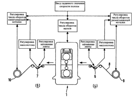
Figure 2.1–Scheme for controlling the tension of the strip and mass flows using movable rollers
In this method, a rolling mill is proposed for cold rolling a metal strip, in particular of steel, with a rolling stand and means for setting a gap between the rolls. Also presented are winders for unwinding and winding strips located before and after the rolling stand, respectively, characterized in that between the winder for unwinding the strip and the rolling stand is a strip storage device for regulating the strip tension during rolling with a constantly changing profile of the strip thickness, the drive is made in the form of a movable roller installed with the possibility of regulating its position by the force regulator of its drive device, taking into account the set value of the force obtained on the basis of the actual value of its angular displacement measured on the movable roller and a predetermined value of the tension strip, and also taking into account the specified strip thickness profile.
Based on the above, it can be proposed that between the winder located in front of a separate cold rolling mill stand and the most individual rolling mill stand there is a strip accumulator designed to control the mass flow and to regulate the tension during the rolling process.
Due to the strip accumulator located in the direction of strip movement in front of the individual rolling stand, changes in mass flow or changes in strip speed caused by changes in strip thickness or thickness profile are compensated, i.e. the shape of the curve changes the thickness of the strip.
Thus, the existing system has a number of disadvantages, namely:
- insufficiently high product quality;
- Inconsistency of winder speeds at the entrance and exit of the stand;
- large inertia of the system, i.e. low accuracy and reliability of rolling process control;
- lengthy process of rolling the strip.
2.2 Overview of national sources
B When the position Sʼ of the piston 6 changes as shown in Fig.2.2, to regulate the thickness of the rolled products in the rolling mill, the tension applied to the working fluid at the input and output sides begin to fluctuate.
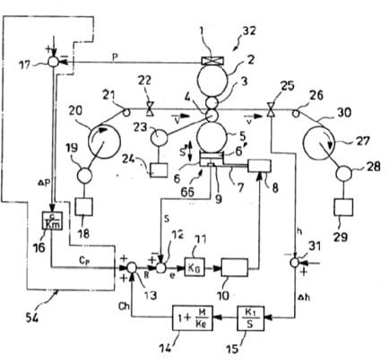
Figure 2.2–The general arrangement of the classic SART reversible rolling mill
If the gap between the work rolls decreases, which leads to a decrease in the thickness of the rolled product, the working fluid will begin to lengthen and the tension on the input and output sides will decrease. Such fluctuations in tension can be absorbed by changing the speeds of the coilers, but they have greater inertia and this absorption is somewhat slower than using the regulation of the gap between the work rolls using a hydraulic system. The result of reducing the tension at the input and output parts is an increase in the deformation resistance of the working fluid, which negates the decrease in the gap between the work rolls, i.e., the thickness of the rolled products does not decrease. In other words, reducing the thickness of the working fluid using a high–speed hydraulic system, it cannot decrease faster than changing the speed of the coilers.
3.Synthesis of automatic strip tension control system
In the synthesis section, as a control object, it is necessary to consider the regulator of the tension of the working fluid in the spaces between the winder and the reversing stand. Since it is he who must compensate for fluctuations in the tension of the steel strip arising from variations in the thickness of the working fluid, which cause an imbalance in the rolling speed ΔV on the input and output sides of the mill.
3.1 Development of a mathematical model of the control object
When developing the concept of constructing the system (Fig. 2.1), it was revealed that the tension regulator serves to change the Youngʼs modulus of the working fluid, therefore it deflects the resonant frequency wn caused by the inertia of the winder and the coefficient of elasticity ( Youngʼs modulus) of the working fluid to the area where they do not affect the regulatory system. Once again, we will repeat the structural diagram of the tension regulator (Fig. 3.1).
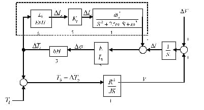
Figure 3.1 – Structural model of the working fluid in the MK–gap
We get an analytical model of the control object according to the structural diagram of the tension regulator (Fig. 3.1). This model reflects the dependence of the change in the tension of the working fluid in the longitudinal direction on a possible change in the rolling speed. According to the structure of Fig. 3.1, while not taking into account the dynamics of the tension regulator, we write the expression in terms of the Laplace transform for changing the tension:
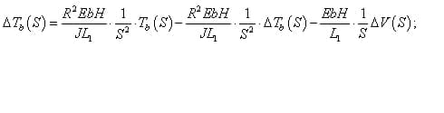
where is E – Young's modulus of the working fluid; b – working fluid width; H – working fluid thickness;
L1 – distance between the working stand and the coiler; J – the moment of inertia of the winder together with the coil;
R – coil radius; S – Laplace operator; ΔV – change in rolling speed; ΔTb – reverse tension change.
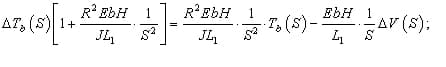
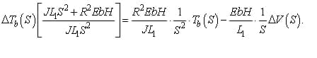
Expressing ΔTb(S), we obtain a solution in operator form for changing the tension between the winder and the stand relative to the required task ΔTb(S) and the disturbing effect of rolling speeds ΔV(S):

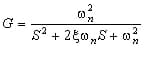
Thus, the transfer function of the object along the perturbation channel change in the tension of the working
has the form:
fluid – change in the speed of the working fluid
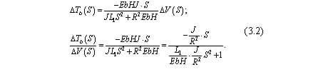
From the expression (3.2) it follows that the dynamics of the perturbation is oscillatory in nature. In order to obtain an expression for the natural frequency of oscillations of the object, we rewrite (3.2) as follows, given that the frequency is the reciprocal of the time constant, then:

From here we get the natural frequency of the oscillations, remembering that when the Laplace operator is squared, the value of the time constant is also squared:

From (3.4) it follows that the natural frequency of oscillations is determined by the structural parameters and can be calculated. Reasoning in the same way, we get the transfer function of the system with blocks inside the area marked with a dashed line (that is, taking into account the regulatory system):

Then, similarly, from expression (3.4) we obtain the expression for the resonant frequency:

where
dynamic characteristic of the tension regulator. From (3.5) it follows that a correctly selected value of the gain of the tension regulator Kt(S) can eliminate the phenomenon of the dependence of tension on the resonance of the winder. Then the thickness of the rolled product will not change, even if the gap between the work rolls changes at a high frequency, as is the case with traditional well-known control systems.
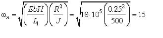
We prove the consistency of the model using methods of mathematical modeling. When modeling an object, the values of the structural and technological parameters are as follows: b – working fluid width 1800 mm; H – the thickness of the working fluid at the inlet is 0.52 mm, at the outlet 0.3 mm; L1 – the distance between the working stand and the winder is 0.5 mm; J – the moment of inertia of the winder together with the coil, 500 kg m2; R – coil radius, 0.25m; V – rolling speed, 20 ... 30 m/s; Tb – working fluid tension, 1020 Kgs = 10000 N. The numerical value of the natural frequency of oscillations is determined by the formula
An analysis of the dynamics of the object, and, accordingly, the consistency of the model will be carried out as a result of modeling the circuit shown in Fig. 3.2. In the diagram, the rolling speed, i.e. the speed of the working fluid is set by a step–like surge with its possible change at the moment of time 5 s.
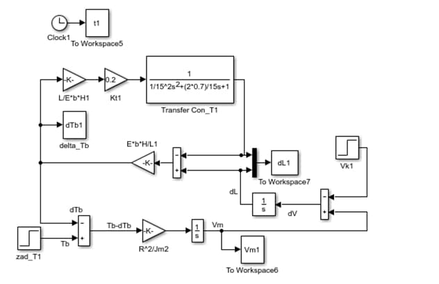
Figure 3.2 – Tension regulator simulation diagram
The winder speed Vm is indignant at the change in the speed ΔV of the working fluid due to a possible change in tension on the input and output sides of the mill and / or due to variations in the thickness of the working fluid, which cause an imbalance of speed through the adder . The transients of the winder speed at different values of the gain of the tension regulator Kt are shown in Fig.3.3. The graphs show that the coefficient Kt varies from 0.2 to 1, changing the transients of the winder speed from vibrational to aperiodic.
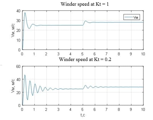
Figure 3.3 – Transient characteristics of the winder speed at various values of the coefficient of the tension regulator
The value of ΔV is integrated into the difference in elongations Δl in the longitudinal direction of the working fluid, the transient characteristics of which are shown in Fig. 3.4. In order to prove the operability of the management concept developed in bachelor's work, in Fig. 3.4. transients of the lengthening of the working fluid without a tension regulator and with a regulator for various values of its gain are specially given. Without a tension regulator, the transition process of elongations and, accordingly, changes in the tension of the working fluid (Fig. 3.5) is oscillatory, which indicates a large inertia of the winder, which is controlled by the deviation of the tension from the required value ΔTb so that compensate for the effect of ΔV. And this compensation happens very slowly (Fig. 3.4 and 3.5 in red).
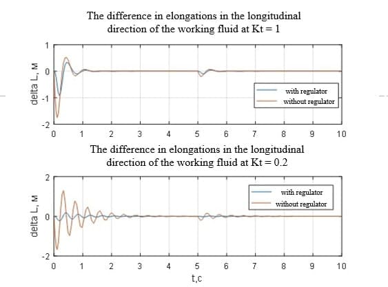
Figure 3.4 – Transient characteristics of the difference in the elongation of the working fluid at different values of the coefficient of the tension regulator
A change in the tension ΔTb is converted to a change in the elongation Δlr (Fig. 3.2). The obtained value is amplified Kt times to obtain the value Δlc, with which the tension is regulated. Thus, the transition process is much faster, since it is not affected by the inertia of the winder (Fig. 3.4 and 3.5 in blue).
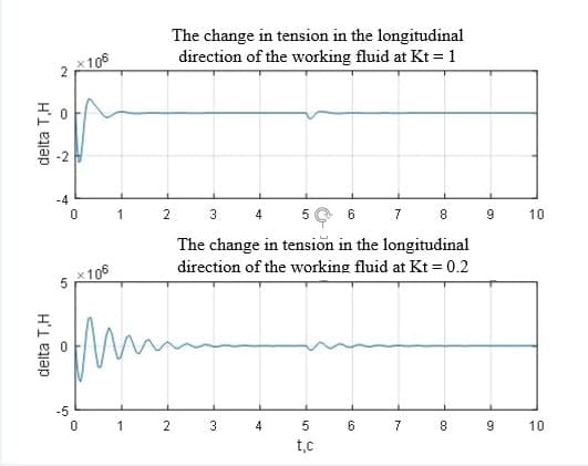
Figure 3.5 – Transient changes in the tension of the working fluid at various values of the coefficient of the tension regulator
Thus, the transient characteristics shown in Fig. 3.3 – Fig.3.5 adequately prove the efficiency of the method of regulating the tension of the working fluid between the winder and the reverse rolling mill. The selection of the gain Kt allows you to compensate for fluctuations in the tension of the working fluid arising for objective reasons. In fact, the tension regulator serves to change the Young's modulus of elasticity of the working fluid, deflecting the resonance frequency wn, caused by the inertia of the winder to the area where it does not affect the control system.
So, in this subsection the control object was described in detail, which is the tension control loop. For the full structure of the tension control system, it is necessary to add a model of an electric drive for the winder, providing a given tension of the working fluid in the gap between the winder and the stand. This model will be discussed in the next subsection.
3.2 Development of a block diagram of an electric winder
To solve the problem, we consider the general principle of tension control [5-10]. The engine moment r necessary to create tension T on the winder coil with radius R is equal to:
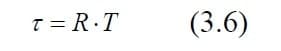
On the other hand, the output torque of the winder motor is:
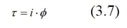
From (3.6) and (3.7), we obtain:
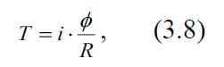
where i – motor current, Φ – field of magnetic induction of the engine. If the regulation is arranged so that the radius of the coil R becomes proportional to the field of magnetic induction f, then Φ/R takes a constant value and the tension T becomes proportional to the current of the motor i.
When developing a mathematical model of a unified DC electric drive (EPU), it is necessary to take into account that its control structure is three–circuit with the principle of subordinate regulation [5-10]. This means that the outer loop is the tension control loop, which sets the job to the inner loop – a speed regulator for the winding motor, which in turn corrects and limits the task of the armature of the winder motor armature current regulator. Such structures of subordinate regulation are implemented in standard unified EPUs.
The mathematical model of a three–circuit self–propelled guns with an electric winder can be represented in the form of a system of integro–differential equations (3.9):
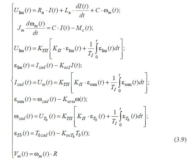
Here, the known functions of time are: UIm(t) – control action (EMF of the electric motor power source) (B), regulated by the PI–control law [5-10]; Uw(t), UTb(t) – control actions for the control loops of the rotation speed of the winder and the tension of the working fluid, respectively, are regulated according to the PI–control law [5-10].
Mc(t) – disturbing effect (the moment of the electric drive’s own load, i.e. the deformation resistance of the working fluid in the deformation zone, reduced to the motor rotor) (H * m).
System parameters are also known:
Unknown in this system are:
w – engine rotation speed (rad/s); I – armature current (A) corresponding to the electromagnetic moment MEM=C * I, (H * m); Tb – winder tension (H).In fig. Figure 3.6 shows the simulation scheme of an automatic control system of an automatic control system of a winder based on a system of integro-differential equations (3.9).
The parameters of the unified electronic control unit, which are necessary for calculating the transmission coefficients and engine time constants, are as follows:
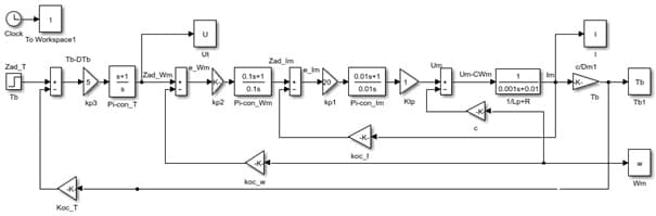
Figure 3.6 – EPU winder simulation circuit
3.3 Analysis of the dynamics of the ATS tension of the steel strip
The analysis of dynamic processes in the system of automatic control of the working fluid tension between the winder and the reversing stand will be carried out as a result of modeling the complete circuit, including the model of the winding control device and tension regulator. This simulation scheme is shown in Fig. 3.7.
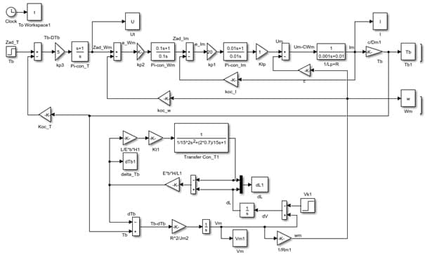
Figure 3.7 – The simulation scheme of the ATS tension of the steel strip
Let's analyze transients in the ATS. Figure 3.8 shows the transient processes of the winding control device with a gain of the tension regulator equal to 0.1.
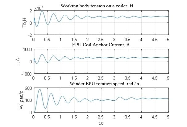
Figure 3.8 – Transients in the winding control system with a coefficient of tension regulator Kt=0.1
It can be seen from the graphs that the processes of the main controlled variables are oscillatory in nature and until the rolling speed changes in 3 s are not set. The winder speed also has an oscillation dynamics (Fig. 3.9). Changes in tension caused by a perturbation of the rolling speed indicate that the winder cannot cope with the compensation of changes in the rolling speed even from 25 m/s to 28 m/s (Fig. 3.10) due to its large inertia.
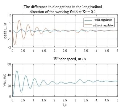
Figure 3.9 – Transient characteristics of the difference in elongations of the working fluid at Kt=0.1
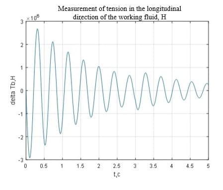
Figure 3.10 – Transient changes in the tension of the working fluid with Kt=0.1
In order to be able to quickly compensate for the resulting fluctuations in the tension of the steel strip, we will adjust the coefficient of the winder regulator Kt, which even with the inertia of the winder will provide a good result due to the deviation of the resonant frequency w n, caused by the inertia of the winder to the area where it does not affect the regulatory system.
Transients in the main controlled variables of the EPC are aperiodic in nature (Fig. 3.11), the control time is 0.8 s, which is a good indicator for objects of this class [10]. Testing changes in rolling speed occurs in 0.25 s.
Transient processes of elongation and changes in the tension of the working fluid along the axis of rolling indicate that fluctuations in the tension of the strip with a change in rolling speed are compensated for 0.5 s (Fig. 3.12, Fig. 3.13).
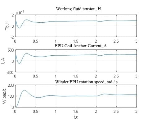
Figure 3.11 – Transients in the winding control system with a coefficient of tension regulator at Kt=1
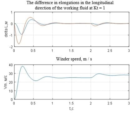
Figure 3.12 – Transients in the winding control system with a coefficient of tension regulator at Kt=1
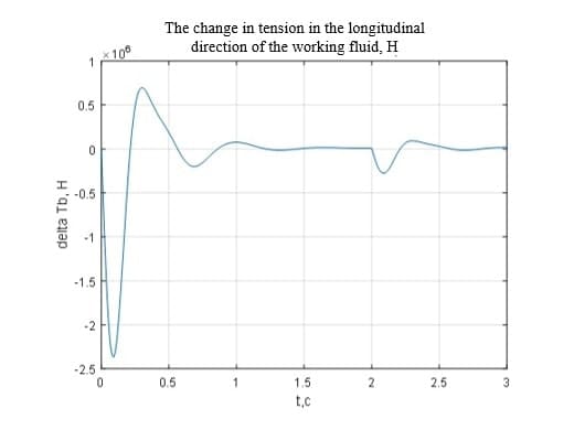
Figure 3.13 – Transient changes in the tension of the working fluid with Kt=1
Thus, the analysis of dynamic processes in the ATS of the tension of the steel strip proved the efficiency of the proposed control concept. The practice of research and modeling of the circuit of Fig. 3.7 showed that the numerical value of the gain of the tension regulator in these technological conditions of reverse rolling, which gives satisfactory results on the speed of the ATS lies in the range from 0.5 to 1 unit.
Conclusion
- A mathematical model of the tension regulator is obtained, which makes it possible to compensate for fluctuations in the tension of the working fluid caused by changes in the speed of the working fluid due to changes in the tension on the input and output sides of the mill and / or due to variations in the thickness of the working fluid. In fact, the tension regulator serves to change the Young's modulus of elasticity of the working fluid, deflecting the resonant frequency caused by the inertia of the winder to the area where it does not affect the control system.
- A mathematical model of the self-propelled guns was developed. It is a three-loop system with subordinate regulation. This model allowed us to perform an analysis of dynamic processes according to the main adjustable variables of the electric winder drive.
- The analysis of the dynamics of the ATS of the tension of the steel strip is carried out according to the general structure of the system, including the winding control system and the tension regulator. Transient analysis of tension ATS has proven the performance of the tension regulator. Transients in the main controlled variables have regulatory quality indicators that meet the requirements for objects of this class. The regulation time is 0.75 s, the perturbation development is 0.5 s.
List of sources
- Дружинин Н.Н. Непрерывные станы, как объект автоматизации. — М.: Металлургия, 1975. — 336 с.
- Выдрин В.Н., Федосиенко А.С. Автоматизация прокатного производства. — М.: Металлургия, 1984 — 472 с.
- Кузнецов Б.И., И.О. Опришко, И.М. Богаенко и др. Автоматизация управления листовыми прокатными станами. — К.: Техника, 1992. — 231 с.
- Гудвин Г.К., Гребе С.Ф., Сальгадо М.Э., Проектирование систем управления, 2004г — 962 с.
- Афанасьев В.С. Автоматизированный электропривод в прокатном производстве: Уч. для вузов. — М.: Металлургия, 1977. — 280 с.
- Комплектные тиристорные электроприводы: Справочник /Под. ред. В.М. Перельмутера. — М.: Энергоатомиздат, 1988. — 319 с.
- Перельмутер В.М., Сидоренко В.А. Системы управления тиристорным электроприводом постоянного тока. М.: Энергоатомиздат, 1988.
- Башарин А.В., Новиков В.А., Соколовский Г.Г. Управление электроприводами: Учебное пособие для вузов. — Л.: Энергоатомиздат. Ленинградское отделение, 1982. — 392 с.
- Ключев В.И. Теория электропривода: Учебное пособие для вузов., 2—е изд. перераб. и доп. — Л.: Энергоатомиздат, 1998. — 704 с.
- Дралюк Б.Н., Конторович Б.И., Маланов А.Л.// Электропривод и автоматизация мощных машин: Сб. науч. тр. — Свердловск: НИИтяжмаш, 1991г. С.81—96.
- Дралюк Б.Н., Конторович Б.И., Маланов А.Л.// Внедрение микропроцессорной САРТ на реверсивном стане холодной прокатки. Изд. "Металлургия", "Сталь" N 5, 1996, с.33—36.
- 7. Тиристорные электропривода прокатных станов /В.М. Перельмутер, Ю.Н. Брауде, Д.Я. Перчик, В.М. Книгин /Под ред. В.М. Перельмутера. – М.: Металлургия, 1978. — 151 с.