Abstract on the topic of graduation work
Content
- Introduction
- 1. Experienced sizing and performance calculation of induction motors
- 1.1. Basic concepts
- 1.2. Idling experience
- 1.3. Short circuit experience
- 2. Determination of the parameters of the equivalent circuit of an induction motor according to reference data
- 3. Calculation of the parameters of the equivalent circuit according to known methods
- conclusions
- Source list
Introduction
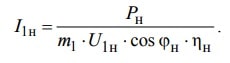
In modern control systems of both direct and alternating current motors, the most accurate determination of their energy and mechanical parameters is necessary for the implementation of the most high-quality and economic control and regulation[1]. It is not always possible to determine the parameters of the engine from the passport data, and if they are only basic information, such as: rated power , rated voltage , rated current , rated frequency and rated speed . For the correct regulation of the electric drive perevodchikam need to have more extensive knowledge about the machine, such as: active resistance stator and rotor inductance of stator and rotor, the flux linkage of the stator, the rotor, which cannot be found in reference materials. This knowledge plays a significant role in modern control systems of electric drives, so there is a need to accurately determine these parameters by calculation or in some other way. Currently, a huge popularity among electric drive control devices are (IF< / abbr>), which calculate the necessary parameters of the replacement circuit automatically according to pre-laid formulas and commands, thanks to which these devices are the best option in the world at the moment in terms of control and regulation of AC motors.
Depending on the different methods of calculating the parameters of the replacement circuit, absolutely different values can be obtained, so it is very important to choose the appropriate method for each engine individually[2].
1. Experimental determination of parameters and calculation of operating characteristics of asynchronous motors
1.1. Basic concepts
There are two methods of obtaining data for constructing the performance characteristics of asynchronous motors: the direct load method and the indirect method. The direct load method consists in an experimental study of the engine in the load range from idle to rated load mode with the measurement of the necessary parameters. This method is usually used for engines with a power of no more than 10-15 kW. With the growth of engine power, the task of its load becomes more complicated, unproductive power consumption and power grid load increase. The application of this method is also limited by the fact that it is not always possible to create a test facility due to the lack of the required equipment and the inadmissibility of overloading the power grid. A more universal indirect method is widely used, the use of which is not limited to the engine power. This method consists of performing two experiments: the no-load experience and the short-circuit experience.
These experiments are easily implemented, and they require a minimum power of the installed equipment. Experimental studies of asynchronous motors in operating modes, as a rule, are not carried out due to their high labor intensity and cost. Characteristics of asynchronous motors in operating modes are obtained by calculation according to the substitution scheme.
1.2. Idle experience
The asynchronous motor is powered in the experiment of H. H. through (IR < /abbr>) voltages (Fig. 1.1) or (AT< / abbr>), which allow you to change the voltage over a wide range, you can also use (TRN) or (NPF)[3]. In this case, the motor shaft must be free from mechanical load. In the scheme there are also measuring devices: ammeter, voltmeter and wattmeter, to remove the necessary physical quantities.
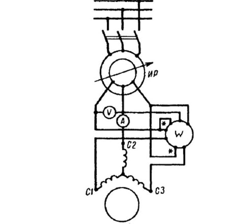
Figure 1.1-Diagram of switching on a three-phase asynchronous motor in the experiments of H. H. and K. Z..
The experience begins with an increased supply voltage
Then gradually lower the voltage to 0.4 u1nom so as to take readings at 5-7 points. In this case, one of the measurements must correspond to the rated voltage U1nom. Measure linear values of voltages and currents and calculate their average values:
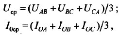
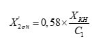
And then, depending on the connection scheme of the stator winding, the phase values of the voltage and current x x are determined.:
When connecting to a star
When connecting to a triangle
The wattmeter W measures the active power Ro consumed by the motor in the Xh mode, which includes electrical losses in the stator winding, magnetic losses in the stator core Pm and mechanical losses Pmex (W):
Here r1 is the active phase resistance of the stator winding (Ohms), measured immediately after disconnecting the motor from the mains so that the winding does not have time to cool down[4].
Sum of magnetic and mechanical losses of the motor (W)
The power factor for the regime of H. H.
Based on the results of measurements and calculations, the characteristics of xh are built.

Рисунок 1.2 – Characteristics of an induction motor (3.0 kW, 220/380 V, 1430 rpm))
For asynchronous motors with a phase rotor, the voltage transformation coefficient between the stator and rotor windings is determined in the experiment of H. H. This coefficient can be determined with sufficient accuracy from the ratio of the arithmetic mean linear (interphase) stator voltages to similar rotor voltages.
1.3. Short circuit experience
The connection diagram of the asynchronous motor in the experiment of K. Z. remains, as in the experiment of H. H. (see Figure 1.1)[5]. But at the same time, the measuring devices must be selected in accordance with the limits of measuring current, voltage and power. The motor rotor should be rigidly fixed, having previously set it to the position corresponding to the average current of the kz. For this purpose, a small voltage is applied to the motor (Uk=0. 1u1nom) and slowly turning the rotor, monitor the reading of the ammeter, the arrow of which will fluctuate depending on the position of the motor rotor. This is explained by the mutual displacement of the tooth zones of the rotor and stator, which causes fluctuations in the inductive resistances of the motor windings.
The limit value of the stator current during the short-circuit test is set based on the permissible current load of the supply network and the possibility of conducting the experiment in the minimum time so as not to cause dangerous overheating of the engine. For engines with a power of up to 1 kW, it is possible to conduct an experiment starting from the rated voltage Uk=U1nom. In this case, the limit current Ik=(5 & ndash;7) Inom. For higher-power motors, the maximum current strength Ik=(2.5 & ndash;5) i1nom. When performing the experiment of KZ for educational purposes, you can limit yourself to the limit current Ik=(1.5 & ndash;2.5) I1nom. When performing the experiment of kz. it is desirable to connect the stator winding with a star.
Defining the range of variation of stator current with the experience of K. h., experience start with the limit values of this current, setting on an induction regulator voltage matching circuit. IR. Then gradually reduce the voltage to a value at which the current I reaches the lower limit of the specified range of its values. At the same time, the readings of the devices are taken for 5-7 points, one of which must correspond to the rated current of the stator (Ik=I1nom). The duration of the experience should be as short as possible. For this purpose, only one linear voltage is measured (for example, UKAV), since some asymmetry of linear stresses does not matter in the KZ experiment. Linear currents are measured in at least two linear wires (for example, IKA and IKV). The arithmetic mean of these two values is taken as the calculated value of the current. After taking the last readings of the instruments, the motor should be switched off and the active resistance of the stator winding phase should be measured immediately to determine the winding temperature. Linear voltages and currents are converted to phase Uk and Ik according to formulas similar to the experience of X. x.
The W wattmeter measures the active power of the Rc. Based on the obtained values of voltages Uk, currents Ik and powers Pk, the following parameters are calculated:
power factor at short-circuit.
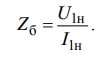
total resistance of the short circuit.
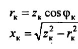
active and inductive components of this resistance (ohms)
The measured and calculated values are entered in the table, and then the characteristics of the KZ are built (Fig. 1.3).
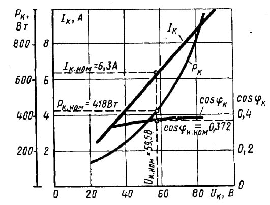
Figure 1.3-Characteristics of an asynchronous motor (3.0 kW, 220/380 V, 1430 rpm)
During the short-circuit test, the motor windings quickly heat up to the operating temperature, since the motor is not ventilated when the rotor is stationary.
The winding temperature is usually determined by the resistance of the base, measured immediately after the experiment, according to the formula:
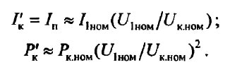
If the winding temperature is less than the calculated operating temperature for the corresponding class of heat resistance of the motor insulation, then the active resistance of the kz. rk is recalculated to the operating temperature:
Then the total resistance of the short circuit is recalculated to the operating temperature.
voltage short-circuit.