


Abstract on the topic of graduation work
Content
- Introduction
- 1. Relevance of the topic
- 2. Purpose and objectives of the study, planned results
- 3. Functional diagram of the control system
- 4. Equipment composition analysis
- 5. Selecting a programmable controller
- 6. Description of engines
- 7. Driver Description
- 8. Module Description Bluetooth
- 9. Principle of operation
- Conclusion
- List of sources
Introduction
With the development of electronics, the microcontroller industry began to develop rapidly, this in turn provides an opportunity to create robots that are able to solve any tasks as in everyday life, and in production.
For a robotic system, one of the most important tasks is the identification of the situation (location) at the current time. The solution to this problem is realized by the development of certain control algorithms. Objects are controlled using artificial intelligence methods, which receive information using computer vision [1].
1. Relevance of the topic
In this work, a crawler–mounted robot was created, which is a prototype of the mechanism, designed for work in hard–to–reach or dangerous places for humans (for example, checking pipelines, tunnels, inspection of the space under stationary vehicles). The eyes of the robot are the PC webcam, the robot is controlled via a wireless Bluetooth connection.
One of the important aspects in this work is the use of computer vision, which is based on a neural network pre–trained to detect two objects.
2. The purpose and objectives of the study
Purpose of work – development automatic system, the meaning of which is that two objects are placed in the camera's field of view. The first object is the grab of a robot manipulator on a tracked traction, the second object the object to which the cart must drive. The control system must detect these two objects in the image, calculate the real distance between them, form a movement task, and process this task with a minimum error.
The system being developed should perform a number of functions and have a number of features, namely:
- The control system must be fully automatic;
- The connection between the robot and the PC should be established automatically, in case of failure, the connection attempt should be resumed;
- The creation of a new frame, as well as the start of the frame processing algorithm, is started only by a signal from the controller board;
- The position system must have a position generator, the job must come in millimeters.
3. Functional diagram of the control system
The functional diagram of the system consists of a web camera that transmits an image to the python environment (PC), the PC, in turn, displays information to the terminal when errors occur, and also exchanges data with the controller via Bluetooth.
Figure 1 shows a functional diagram of the system.
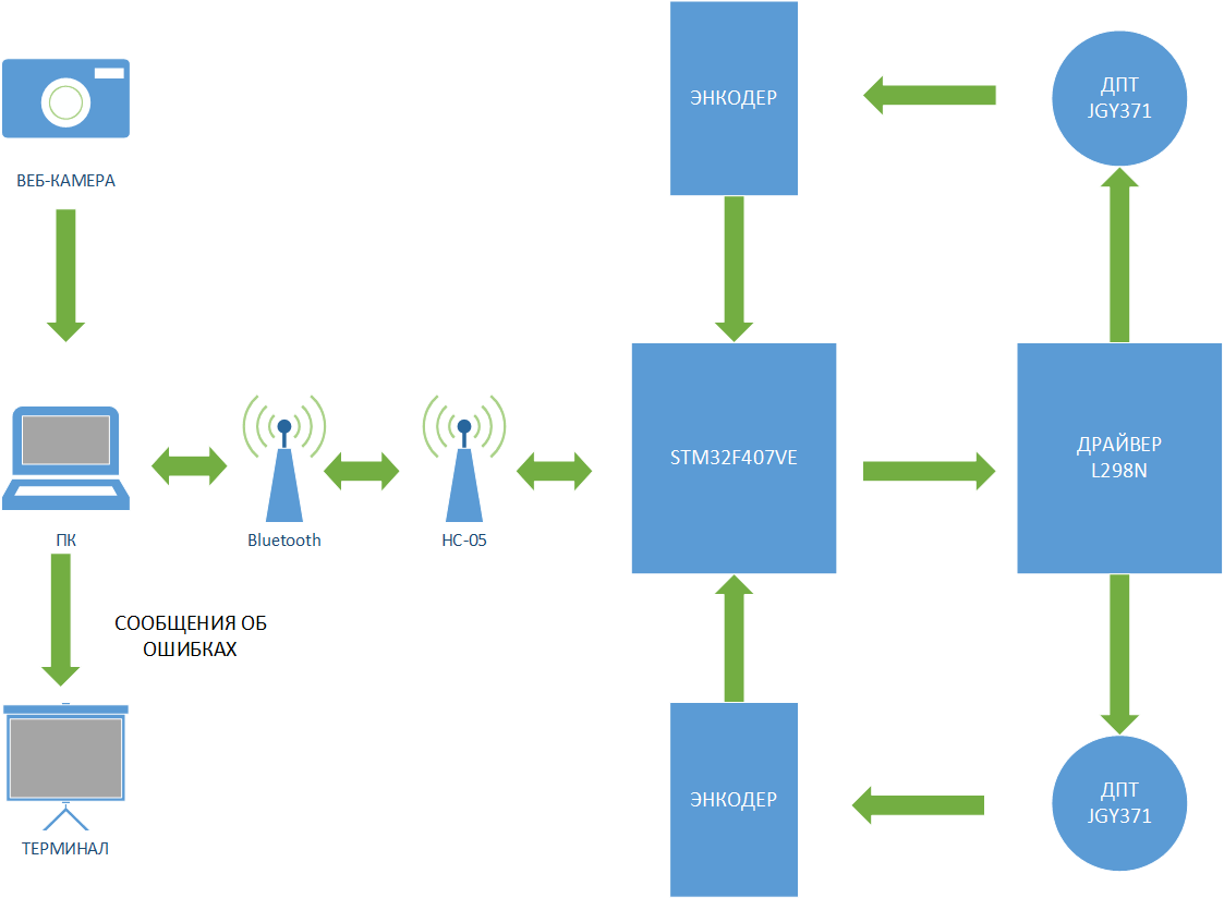
Figure 1 – Functional diagram of the system
The controller, having received data on the location of the searched for objects, calculates the distance between them. Based on the information received, it forms a task for the control system. After that, the corresponding control signals are generated for the driver, which in turn controls the platform motors.
The information about the distance traveled by the robot is taken from the encoders and transmitted via wires back to the controller.
4. Equipment composition analysis
Since the platform is a mobile base on which the manipulator will subsequently be mounted, at the design stage it was necessary to take into account the approximate values ??of the weight and size indicators of the manipulator, the material from which it will be made, and also take into account the maximum distance of movement of the gripper, based on the above indicators, a decision was made to maximize to underestimate the platform to shift the center of gravity, to increase the mass of the platform due to metal structures that served as the base of the frame. Thus, the platform rollover was minimized, but this was not enough, therefore, already at the assembly stage, it was decided to increase the width and length of both the tracks and the bases for their fastening.
A metal corner measuring 20x30mm was chosen as the base for the tracks, due to the properties of the structure of the corner rib, the rigidity of the track is ensured.
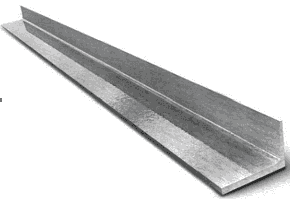
Picture 2 – Metal corner 20x30mm
The structure of the platform consists of two metal corners, fastened together, to which the systems of gears and rollers are attached.
The lower rollers are fixed on springs, thus at the same time providing the necessary tension of the tracks, and also increasing the robot's permeability on uneven surfaces.
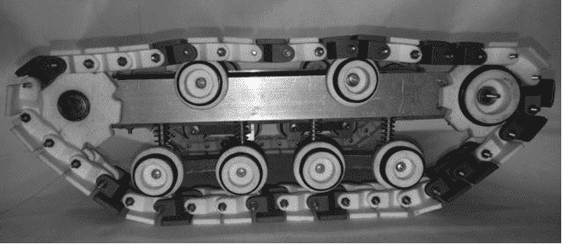
Figure 3– Caterpillar assembly
5. Selecting a programmable controller
The controller is the STM32F407VET6 debug board, on the basis of which the robot's logic is built.
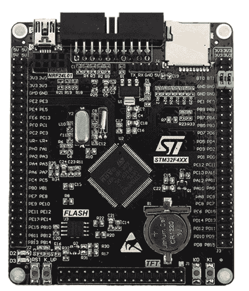
Figure 4 – General view of the debug board
The main characteristics of the development board:
- Microcontroller STM32F407VET6 with quartz at 8 MHz;
- Special block 16x2 for working with TFT;
- Block for debugging / programming 2x10 JTAG / DBG IDE;
- Socket (female), for connecting the NRF41L01 radio module;
- Slot for mini SD memory card;
- Mini USB connector, which can be used to connect the board as a virtual COM port. You need to preinstall ST VCP driver;
- Four buttons (RST, K_UP, K0, K2);
- Real time clock with quartz resonator 32.768 kHz;
- Separate Winbond 25q16bvsig flash memory chip, which is programmed with SPI1, just like nRF2401 (different CS pins).
The development board is programmed using the MATLAB software package, the Waijung library, which greatly simplifies the task of programming and debugging algorithms.
6. Description of engines
The original version of the traction motors were Arduino motors with a plastic gearbox, the power of which was 1W, but in the process of increasing the weight and dimensions of the platform, as well as due to the numerous shaft backlash caused by the plastic gears of the gearbox, it was decided to change the type of motor.
The main criteria for choosing a motor were such indicators as: the cost of the motor, high developed torque, supply voltage (DC12V), low no–load current, low rated current, convenient motor mounts, a metal gearbox, as well as the presence of an encoder for calculating speed, position, distance traveled and working off a given trajectory, etc.
Based on the above criteria, a 1.5W type JGY371 DC motor was selected, which is equipped with metal step–down gears and incremental encoders.
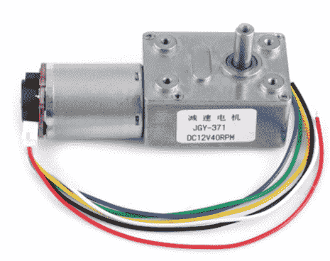
Figure 5 – JGY371 DC Motor
Rated voltage 12V DC, output speed 100 rpm, rated torque 1.5 kg.cm, maximum torque 6.4 kg.cm, gear ratio 40.
Data on the value of the current were obtained experimentally, the no–load current, taking into account the caterpillar on the shaft, is 150mA. The engine weighs 165 grams.
Pin assignment:
- Red – positive motor power lead;
- White – negative motor power lead;
- Blue – positive power output of the encoder;
- Black – negative encoder power lead;
- Yellow and green – feedback pins
7. Driver Description
The L298 is an integrated 15–pin monolithic circuit. It is a high voltage dual full pass high current driver designed to accept standard TTL logic levels and drive inductive loads such as relays, solenoids, DC and stepper motors. The two enable inputs can enable or disable the device independently of the input signals.
The emitters of the lower transistors of each bridge are connected to each other, and the corresponding external terminal can be used to connect an external sense resistor. An additional power input is provided so that the logic operates at a lower voltage.
Technical features:
- Driver L298N;
- Medical equipment;
- Motor voltage up to 35 V;
- Logic voltage: 5 V;
- Size 44 x 44 x 30 mm.
Input description [ 6 ]:
- Vcc – engine power;
- GND – earth;
- OUT1, OUT2 – first channel output;
- OUT3, OUT4 – second channel output;
- ENA – enable the first channel;
- IN1, IN2 – direction of the first channel;
- ENB – enable the second channel;
- IN3, IN4 – direction of the second channel.
The appearance of the L298N driver is shown in Figure 6.
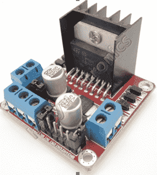
Figure 6 – L298N Driver
8. Bluetooth module description
Bluetooth communication was chosen due to its ease of implementation, it provides immunity to interference (broadband), and this in turn allows multiple devices that interact with each other to communicate with each other and not affect the work of others. Line–of–sight is not required to control the robot, which is a significant plus, since the robot's eyes are a web–camera.
Specifications:
- Radio frequency range: 2.4 – 2.48 GHz;
- Transmit power: 0.25 – 2.5mW;
- Sensitivity: – 80 dBm;
- Supply voltage: 3.3 – 5 V;
- Current consumption: 50mA;
- Radius of action: up to 10 meters;
- Interface: serial port;
- Modes: master, slave;
- Dimensions: 27 x 13 x 2.2 mm.
Connection
- VCC – (supply 3.6 6 V);
- GND – (ground);
- TXD, RXD – UART interface;
- STATE – status indicator;
- KEY – contact to enter programming mode.
The module is shown in Figure 7.
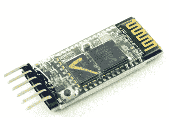
Figure 7 – HC–05 module appearance
9. How it works
The system operation algorithm is divided into two parts. Each part of – is an individual system. Each of them has a computing core and a Bluetooth module.
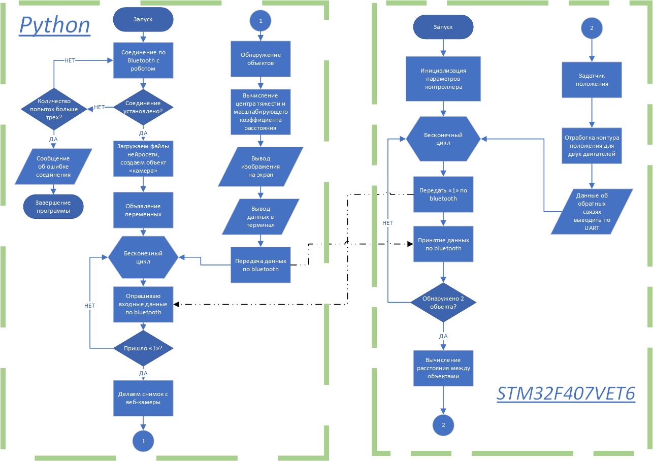
Figure 8 – System operation algorithm
Python file is launched on the PC, loads the neural network structure file and the neural network file. Further, on a signal from the controller, it takes a picture from the web camera, processes the data, finds the theoretical center of gravity of objects, while if the system has detected more than two objects, it selects and takes as a basis those objects that have the highest probability of detection. After these steps, the data is sent via Bluetooth to the controller.
The controller receives this data, calculates the real distance between the desired objects, this information goes to the position generator, after that to the single–loop position system.
Figure 9 – Object detection algorithm operation
(animation: 6 frames, 7 cycles of repetition, 106 kilobytes)
Conclusion
A significant drawback of this system is that for the functioning of this system, two computing cores are required, namely: a controller and a PC.
The quality of system detection and the accuracy of determining the distance between objects directly depends on the number of photographs of objects in the process of training the neural network and on the number of training epochs. Also, the performance of the webcam affects the accuracy of the system.
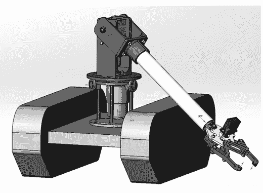
Figure 10 – Robot at the design stage
This control system determines the distances between objects, provided that they are on the same straight line, in the future it is planned to complicate the system in order to determine the coordinates in the plane.
When writing this essay, the master's work has not yet been completed. Final completion: June 2021. The full text of the work and materials on the topic can be obtained from the author or his manager after that date.
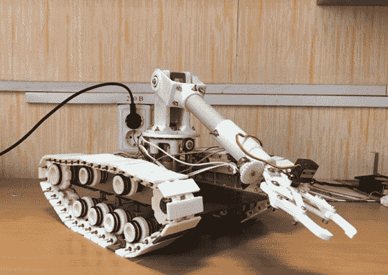
Figure 11 – Robot underway
List of sources
- Simulink. [Electronic resource]. – Access mode: https://matlab.ru/products/Simulink
- WaijungBlockset. [Electronic resource]. – Access mode: http://waijung.aimagin.com/
- Reflective Optical Sensor with Transistor Output, DataSheet № TCRT5000
- DUAL FULL–BRIDGE DRIVER, Electronics Description, DataSheet № L298N
- Eclipse (development environment). [Electronic resource]. – Access mode: https://www.eclipse.org/
- IIC interface bus (I2C). [Electronic resource]. – Access mode: http: //easyelectronics.ru / ...
- Management of mobile robots [Electronic resource]. – Access mode: https: //moluch.ru / ...
- STM32F407VE [Electronic resource]. – Access mode: https: //www.st.com / ...
- CMOS Rail–to–Rail General–Purpose Amplifiers, DataSheet № AD8541_8542_8544
- HC–05 digital line sensor. [Electronic resource]. – Access mode: https://3d–diy.ru/wiki/arduino–moduli /