

Abstract on the topic of graduation work
Contents
- Introduction
- 1. Relevance of the topic
- 2. Purpose and objectives of the study, planned results
- 3. Research & Development Overview
- 4. Implementation of an active rectifier control system based on the STM32F407 microcontroller
- Conclusions
- List of sources
Introduction
The accelerating pace of technological progress requires the systematic use of increasingly intelligent technical systems.
Today, along with the cost reduction and increasing availability of systems-on-a-chip (SoC – System-on-Chip), the development of technologies user-programmable gate arrays (FPGAs – Field-Programmable Gate Arrays), the requirements for accelerating and reducing the cost of the development of computerized control systems of different classes. In particular, there is a growing need to create control systems for power electronics (inverters, rectifiers, etc.) for large, medium and small production.
These trends have spawned the paradigm of Model-Based Design: ideology and tools, allowing to implement all stages of the life cycle of creating complex technical systems, from theoretical substantiation the feasibility of the task before writing control programs to controllers, signal processors and programmable logic integrated circuits. All the listed possibilities can be provided by the MatLab computing environment by MathWorks.
1. Relevance of the topic
Industry is currently the main consumer of electricity in the world. In turn, in the industry, the main electrical consumers are non-linear elements: electric drives and power electronic devices. The operation of such consumers without compensating measures leads to distortions of the consumed current and mains voltage, as a result of which:
- power losses increase at all stages of electricity conversion;
- there is a decrease in the electrical and mechanical efficiency of the loads;
- the required capacity of autonomous electric power plants is forcedly overestimated;
- the service life of electrical products is reduced, etc.
Also, one of the most important problems is the return of electricity to the network, especially in powerful drives operating in intermittent modes
These requirements and negative consequences, as well as strict national and international laws to improve energy efficiency, entail significant losses of material resources for the industry.
One of the main tasks of power electronics is to ensure the electromagnetic compatibility of network converters with the AC supply network and to meet all requirements for its quality. In the field of electric drive, in turn, it is required to ensure the operation of the engine in four-quadrant mode.
The requirements of international standards IEC 61000-3, IEEE 519, EN 61000-3-2 strictly regulate the level of harmonic components of the current consumed by an electrical device, up to harmonic 49. Domestic GOST R 51317.3.2-99 (IEC 61000-3-2-95) is limited to harmonics up to the 40th.
One of the main directions of reducing the harmonic effect of converters on the supply network and load, reducing the consumed reactive power and ensuring recuperation is the transition to the use of active rectifiers. In the English-language literature, the generic term AC / DC converter is used in accordance with the terminology of the IEC 60050-551 standard (AC / DC Converter). Active front end (AFE), Grid Side Inverter, Active rectifier are also common.
The master's thesis is devoted to the scientific and technical problem of developing a control system for an active rectifier, using the most advanced tool for fast and cheap creation of embedded control systems – Model-Based Design (MOD). This approach has already proven itself well in large monitoring and control systems, especially in the nuclear power industry. Now, with the advent of affordable and powerful SoCs and graphical programming and debugging environments (SimTech, Simulink, etc.), the trend of using MOD is spreading to power electronics.
The Simulink environment of the MATLAB package and the Keil IDE is used as a modeling and programming environment, and an STM32F407VGT microcontroller from STMicroelectronics is used as a material implementation.
2. Purpose and objectives of the study, planned results
The aim of the work is to study the applicability of Model-Based Design to the development of power electronics, to significantly accelerate and simplify the development of industrial power converters.
The main objectives of the research:
- Mathematical description of the control object;
- Synthesis of the object control system;
- Modeling the operation of the control system and object in the Simulink environment of the Matlab package;
- Upon achieving the required results, generate the control system code in C;
- Power converter prototype development and microcontroller programming.
3. Research & Development Overview
At the moment, there are many approaches to the synthesis of control systems for power electronics, however, there are not so many works devoted to implementation issues, which makes any research with a proposal for a practical implementation method very valuable.
The principle of operation of an active rectifier and its area of application are discussed in detail by Bimal Kumar Bose in his book Modern power electronics and AC drives
[1]. In this book
there are also many ways to control power converters and electric drives, proposed and considered their different topologies,
the methods of synthesis and implementation of control systems based on fuzzy logic and neural networks are considered.
In addition to fundamental works, for narrower information on the application, mathematical description and current trends in the development of active rectifiers (power correctors), you can contact
to sources authored by N. Mohan, M. Andland, P. Robbins, F. Blobjerg, D. V. Kolar and D. Muleteler [2] and [4].
Since active rectifiers are widely used where two-way energy exchange is required and maintaining high quality network parameters,
many control methods have been proposed, which vary greatly depending on the application. For example, in the work of authors Jian Xu, Xin Cao and Zhenyang Hao [5]
a control system based on the Droop control
or Static control
strategy is proposed. This approach is used in local power supply networks Microgrid
, which can operate autonomously. In such networks,
depending on the type and size of the load, the mains voltage and its frequency can vary greatly. The Droop control method allows you to minimize these changes,
due to the correct control of the active rectifier. In wind turbines, an important role is played by the quality of synchronization of each installation (wind turbine
) with the general network and maintaining a constant frequency and voltage regardless of the speed of the blades.
To solve this problem, an article by the authors Intao Ma, Tszudo San and Jianyun Chi [6] proposes a control system with PI-current regulators, providing a sinusoidal network current with a variable power factor.
Also, in a similar work by George Alin Raduku [7], a much wider range of possible solutions to the described problem is given, a calculation of network filters and an example of a practical implementation of a power plant are given.
4. Implementation of an active rectifier control system based on the STM32F407 microcontroller
To apply the MOD principle, you first need to compose a mathematical description of the object according to the electrical diagram in Figure 1 in the Laplace area and bring it to the form of a structural diagram. This circuit is shown in Figure 3. The sequence of switching on the keys is shown in Figure 2. After that, you can synthesize the control system by any of the known or available methods. The block diagram of the control system is shown in Figure 4.
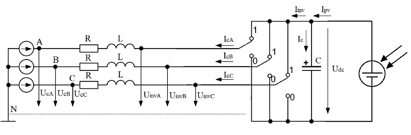
Figure 1 – Schematic diagram of an active rectifier
Figure 2 – The sequence of switching on the keys
(animation: 5 frames, 6 repetition cycles, 14 kilobytes)
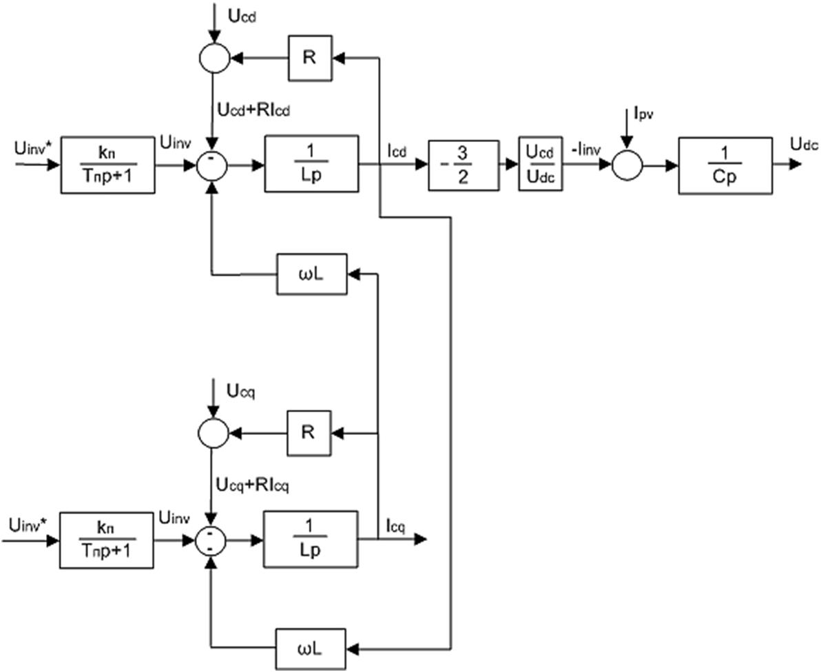
Figure 3 – Block diagram of the regulated object
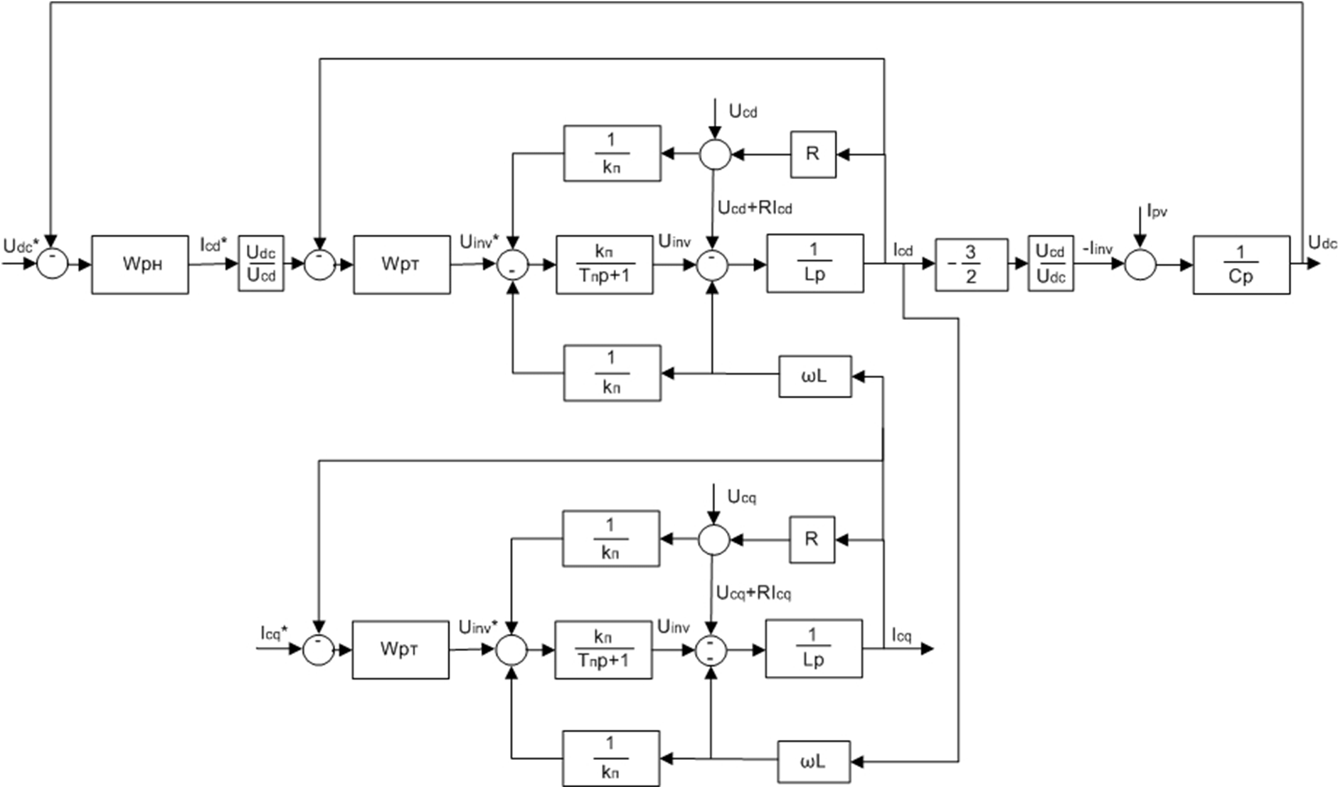
Figure 4 – Control system
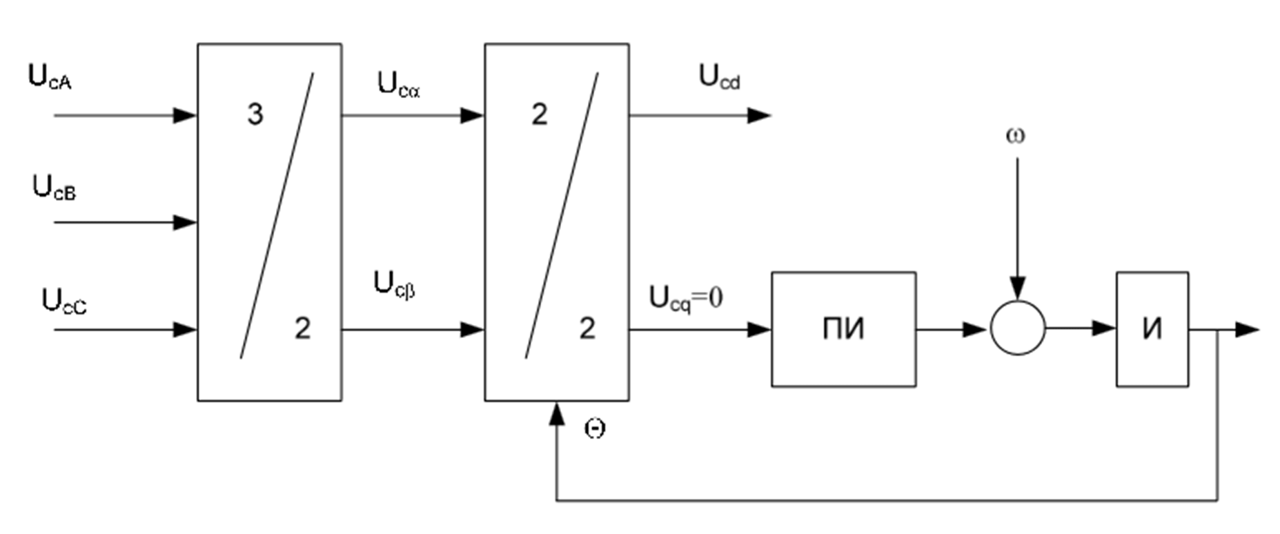
Figure 5 – General view of the PLL system
After the theoretical part of the development is over, it is necessary to create a control system using MATLAB tools in the Simulink environment. A screenshot of the model is shown in Figure 6.
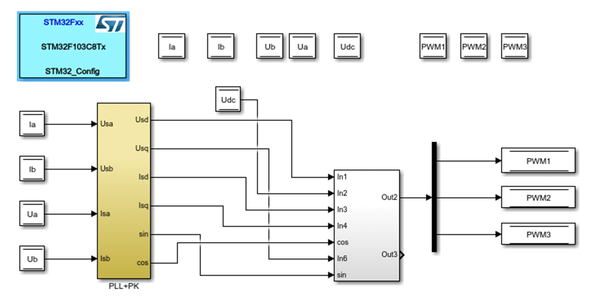
Figure 6 – Control system in the Simulink environment
After MATLAB has generated the code for the generated model, it can be loaded into the microcontroller from any IDE.
Conclusions
The paradigm of synthesis of control systems based on the MOD principle is now becoming more and more applied in the field of power electronics, and this work confirms this. What previously had to be done by hand: writing code, creating libraries and adapting to the specifics of the microcontroller's work – now you can do assembling the constructor
in a suitable graphical environment. And preliminary simulation of the entire system will save the engineer from costly mistakes and will save him from lengthy tests and adjustments on a small scale
, which will greatly save time and money.
As part of the work done:
- A mathematical description of the control object has been created.
- The control system is synthesized.
- The control system was modeled and implemented in the Simulink environment.
- The code in the C language has been developed, which implements the system on the STM32F407 microcontroller.
Further research focuses on the following aspects:
- Development of a transistor converter with current and voltage sensors.
- Experimental verification of system performance on a
small scale with reduced voltage.
- Creation of a full-fledged converter for an imaginary voltage of 380V, 50 Hz.
When writing this essay, the master's work has not yet been completed. Final completion: June 2021. The full text of the work and materials on the topic can be obtained from the author or his manager after that date.
References
- Bimal K.B. Modern Power Electronics and AC Drives / K.B. Bimal — Prentice Hall, 2001. — 736 pp.
- Ned Mohan, Tore M., P.Robbins. Power Electronics/ Ned Mohan, M. Tore, Robbins P. — Prentice Hall, 2002. — 409 pp
- Frede B. Control of Power Electronic Converters and Systems/ B. Frede — Academic Press, 2018. — 532 pp
- The Essence of Three-Phase PFC Rectifier Systems [Электронный ресурс]. — Режим доступа: https://ethz.ch/content/dam....
- Xu, J., Cao, X., & Hao, Z. A Droop Control Strategy Based on Synchronous Rectifier to Modulate the Frequency and Voltage in AC Microgrid. [Электронный ресурс]. — Режим доступа: https://ieeexplore.ieee.org/document/8921702/.
- Ma, Y., Sun, X., & Chai, J. Synchronous PI current control technique for three-phase PFC rectifier for PMSG wind generation system. [Электронный ресурс]. — Режим доступа: https://ieeexplore.ieee.org/document/5545885.
- George Alin RADUCU Control of Grid Side Inverter in a B2B Configuration for WT Applications / RADUCU George Alin — Aalborg University, 2008. — 103 pp.
- Jie Feng Hu, Jian Guo Zhu, & Platt, G. A droop control strategy of parallel-inverter-based microgrid [Электронный ресурс]. — Режим доступа: https://ieeexplore.ieee.org/document/7513771.
- M. Liserre, A. Dell'Aquila, F. Blaabjerg, Design and control of a three-phase active rectifier under non-ideal operating conditions [Электронный ресурс]. — Режим доступа: https://ieeexplore.ieee.org/document/1042708.
- Sangshin Kwak, & Toliyat, H. A. Current-source-rectifier topologies for sinusoidal supply current: theoretical studies and analyses. [Электронный ресурс]. — Режим доступа: https://ieeexplore.ieee.org/document/1637840.
- Cichowlas, M., Malinowski, M., Jasinski, M., & Kazmierkowski, M. P. DSP based direct power control for three-phase PWM rectifier with active filtering function. [Электронный ресурс]. — Режим доступа: https://ieeexplore.ieee.org/document/1267928.
- H. Ma, M. Yang, Y. Chang, J. Zhao, Y. Lu, Predictive Direct Power control for Three-phase Vienna Rectifier with Simplified SVM, IEEE International Power Electronics and Application Conference and Exposition (PEAC), 2018
- X. Li, C. Zhang, A. Chen, X. Xing, G. Zhang, Model Predictive Direct Current Control Strategy for Three-Level T-type Rectifier Under Unbalanced Grid Voltage Conditions IEEE Applied Power Electronics Conference and Exposition (APEC), 2018
- F. Tlili, F. Bacha, M. Guesmi, New Switching Lookup Table for Direct Power Control of a Three-Phase PWM Rectifier, The 9th International Renewable Energy Congress (IREC),2018
- M. Jamma, M. Akherraz', M. Barara, ANFIS Based DC-Link Voltage Control of PWM Rectifier-Inverter System with Enhanced Dynamic Performance, 44th Annual Conference of the IEEE Industrial Electronics Society, IECON, 2018.
- Гельман, М.В. Преобразовательная техника: учебное пособие / М.В. Гельман, М.М. Дудкин, К.А. Преображенский. — Челябинск: Издательский центр ЮУрГУ, 2009. — 425 с.
- Пронин М.В., Воронцов А.Г. Силовые полностью управляемые полупроводниковые преобразователи (моделирование и расчет) / Под ред. Крутякова Е.А. СПб:
Электросила
, 2003. — 172 с. - Аванесов, В. М. Релейное управление следящими статическими преобразователями. Ч. 1. Структуры систем управления: анализ и синтез [Текст] / В. М. Аванесов // Электричество. — 2000. — № 10. — 45-53.
- Шрейнер Р.Т. Математическое моделирование электроприводов переменного тока с полупроводниковыми преобразователями частоты. — Екатеринбург УРО РАН, 2000 г. с. 273 – 288.
- Ю.Н, Калачев,
Моделирование в электроприводе
, ЭФО, 2013. - Самарский. Г.С, Мирошник Д.Н. ПРИМЕНЕНИЕ АКТИВНОГО ВЫПРЯМИТЕЛЯ В КАЧЕСТВЕ ЭНЕРГОСБЕРЕГАЮЩЕГО ЭЛЕМЕНТА В ЭЛЕКТРОПРИВОДЕ [Электронный ресурс]. — Режим доступа: http://masters.donntu.ru/2005/eltf/samarsky/library/st21/st21.htm.
- Нусратов, П.Р. Разработка и исследование энергосберегающего электропривода шахтных подъемных машин. — Новокузнецк ФБГОУ ФО, 2016 г. с. 21