
Abstract
Content
- Introduction
- 1. Relevance of the topic
- 2. The purpose and objectives of the study
- 3. The device and principle of operation of the valve-inductor motor
- 3.1 Design of SRM
- 3.2 How the SRM works
- 4. Control of a switched reluctance motor
- 4.1 Determination of SRM commutation angles.
- 4.2 Modeling SRM
- Conclusions
- List of sources
Introduction
The valve-inductor motor is one of the oldest electric motors developed in the period from 1830 to 1850. Due to the complexity of management, it could not find widespread use and, thus, gradually lost its relevance until the middle of 1960. until development began in the field of power electronics. This prompted researchers to investigate the possibility of using a view with more advanced control. In this engine, the torque is created due to the tendency of its rotating part (rotor) to move to the position, in which the inductance of the excited winding is maximum.
1. Relevance of the topic
With the development of power electronics, the switche reluctance motor (SRM) has become a competitive choice for some industrial installations in electrical machine control systems due to its simplicity and robust design. SRM have such advantages as rotor simplicity, high operating speed, ease of repair, and a high degree of independence between phases. SRM actuators are used in aerospace systems, marine propulsion systems, linear actuators, mining actuators, hand tools, and household applications. In this motor, the torque is created due to the tendency of its rotating part (rotor) to move to a position in which the inductance of the excited winding is maximum..
Nowadays, the reduction of torque ripple in the view has become an important and complex research topic. Torque ripple is very severe, especially at low speed, causing unwanted vibration and acoustic noise.
2. The purpose and objectives of the study
On the basis of literature sources and research of SRM, study on a mathematical model the peculiarities of using SRM for industrial and power plants. In the Matlab package, develop a model and simulate the operating modes of the engine.
3. The device and principle of operation of the switched reluctance motor
3.1 Design of SRM
The switched reluctance motor can have various designs. As an example, Fig. 1 shows a machine 8/6, where 8 is the number of pairs of stator poles, and 6 – number of rotor teeth.
Picture 1 – Cross section of 4-phase VIEW with version 8/6
(animation: 8 frames, 116 kilobytes)
SRM has the following design features:
- the stator and rotor cores have a salient pole structure;
- the number of pole pairs is relatively small, while the number of stator poles is greater than the number of rotor poles;
- stator and rotor cores are laminated;
- lumped coil stator winding. It can be single or multiphase;
- a motor phase usually consists of two coils located at diametrically opposite stator poles. Machines with double the number of stator and rotor poles are known. These 4-phase electrical machines have a 16/12 configuration. The phase of such a machine consists of two pairs of coils, which are located on the stator poles in such a way that their axes are orthogonal;
- phase coils can be electrically connected in parallel or in series, magnetically - according to or opposite;
- Rotor winding SRM missing
Figure 2 shows a view of various configurations
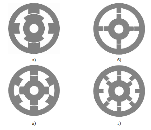
Figure 2 – Various SRM configurations: a - single-phase configuration 2/2; b - two-phase configuration 4/4;
v - three-phase configuration 6/4; d - four-phase configuration 8/6
Structurally, the VID, the frequency converter and the control system in the VIP can be performed separately. Moreover, in the process of work, they can be at a fairly large distance.
3.2 How the SRM works
The principle of operation of the SRM motor is quite simple: when a current passes through one of its stator windings, torque is created due to the tendency of its rotor to align with the excited pole of the stator. The direction of the generated torque depends on the position of the rotor with respect to the phase to which the voltage is applied and is independent of the direction of flux in that particular winding. The torque can be performed continuously by synchronizing the excitation of each phase winding with the position of the rotor. The current passing through the SRM winding is regulated by the appropriate switching on and off of the power electronic switches, which can connect each phase of the SRM to the DC bus.
On the same shaft with an electromechanical converter (EMC), a rotor position sensor (RPS) is fixed. Each phase of the EMC generates torque only in a certain range of rotor rotation angles. In this range of angles, the RPS generates a signal that enters the microprocessor and then, through a matching device, to an electronic switch powered by a direct current source. When a signal enters the electronic switch, the corresponding phase of the EMC is connected to a DC source. When the operating range of the rotor rotation angles is exceeded, the RPS signal is stopped and the corresponding phase is short-circuited to itself, and then connected to the voltage of reverse polarity. This connection leads to a rapid drop in phase current to zero.
The position of the rotor tooth, in which its axis coincides with the axis of the stator tooth, is called consistent, and the position in which the axis of the stator tooth passes along the axis between two adjacent rotor teeth is mismatched. So for phase A there is a mismatched position (Fig. 3a), and for phase C - a consistent one.
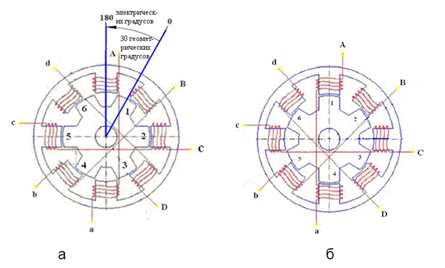
Figure 3 – Construction of a four-phase VIEW with an 8/6 ratio
a) - in an inconsistent position relative to the teeth of phase A;
b) - in an agreed position relative to the teeth of phase A.
Typically, a brushless jet motor has three or more phases. But there are also special designs with two or one phase. To switch at the right moment, the machine is usually equipped with a rotor position sensor. There are also sensorless control methods based on stator current or torque.
4. Control of a switched reluctance motor
A typical SRM drive system consists of three main components: a power electronic converter, a logic control circuit and a motor.
4.1 Conrol system of SRM
Machines in most cases operate with variable speed. Figure: 4 shows the control circuit. The power section consists of a source, a converter and a machine. The sensors usually require a rotor position sensor and a phase winding current sensor.
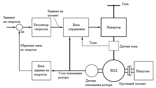
Figure 4 – SRM circuit with speed control system.
The angle of rotation determines the speed of rotation. The control deviation sets the torque setpoint (drift or deceleration). However, unlike conventional drives, in the slave current control circuit, the torque cannot be directly adjusted, because current is not a direct indicator of torque. Rather, the torque only indirectly affects the amplitude of the current (in the lower rpm range, pulse mode) and shift angles (especially at higher rpm, block mode).
Therefore, the relevant information must be stored in digital memory and retrieved to control the inverter according to the current operating state (depending on rotation speed and load).
4.2 Determination of switching angles for SRM
Determination of commutation angles to obtain maximum shaft power over the entire speed range.
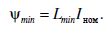
To find the commutation angles that provide the maximum shaft torque and power for each speed. Then it is necessary to achieve pairing with unrivaled position and rated current:
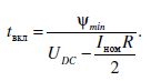
This magnetic coupling must be achieved the moment the inductance starts to rise. Then the time required to achieve the rise in flux when the BCC voltage is applied is is determined by the ratio of the current and voltage BCC minus the voltage drop across the active phase resistance. The voltage drop across the active phase resistance is small (in relation to the DCB voltage), and the current increases, so this value can be approximated by the average value that allows you to determine the time:
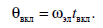
This time can be expressed through the commutation advance angle, which will change along with the speed of rotation of the electric motor:
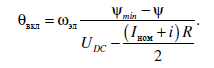
The expression is given for an intermittent current mode, but the current may not necessarily be zero when a phase is required to turn on again in order to reach the rated current by the time the inductance increases region begins. Then the switching advance angle should track the current value of the phase flux linkage:
Since the flux changes during the operation of the phase, this angle is constantly changing, but at some point it becomes larger than the current angle, and the phase must be turned on. In this case, the maximum commutation advance angle should not go beyond point A (Fig. 6).
Phase disconnection should occur at a minimum angle corresponding to the beginning of the maximum inductance zone (point C in Fig. 6). In this case, the phase current must have time to drop to 0 before the region with decreasing inductance begins, otherwise there will be a tendency for the regenerative current to increase, leading to a significant increase in the braking torque. The formula for calculating the phase cutoff angle relative to point B in Fig. 6:
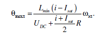
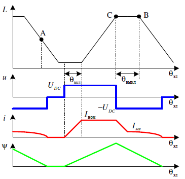
Figure 6 – Explanation of the angles of commutation.
In addition, the width of the phase switching zone should be limited, which should not exceed 180° in static. A slight excess is possible to compensate for the voltage drop across the active resistance of the winding
4.3 Modeling SRM in Matlab
Model SRM 8/6 built in Matlab / Simulink is shown in Fig. 7. Additional control elements with PI regulator have been developed to increase the efficiency of the switched reluctance motor.
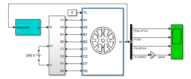
Figure 7 – Modeling SRM 8/6 in Matlab
The currents of the four stator phases are shown in Fig. 8. The flux induction saturates at the point where the velocity becomes constant. Initially, when the motor is started, it draws a large current proportional to the torque.
Simulation results
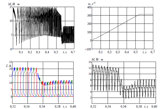
Figure 8 – Transient graphs SRM.
Conclusions
The developed simulation model makes it possible to study electromagnetic and electromechanical processes in a valve-inductor drive, and also analyze various management methods. An improvement in the performance of the SR is achieved with the use of a PI controller. With these methods, you can analyze a wide range of on and off angles instead of the usual two on and off angles. The proposed control scheme not only increases the efficiency of the SRM, but also provides a wide range of current values.
References
- Krishnan, R. Switched reluctance motor drives: modeling, simulation, analysis, design, and applications. / R. Krishnan. – Magna Physics Publishing, 2001. – 416 p.
- Киреев, А.В. Вентильно-индукторные электроприводы для подвижного состава. / АкадемЛит, 2011. – 340 с.
- Рымша В.В. Усовершенствованная цепно-полевая модель вентильно-реактивного двигателя. / Електротехніка і Електромеханіка. – 2010. – No 5. – С. 24–26.
- Petrushin A.D. Optimizatsiya aktivnoy chasti ventil'no-induktornogo elektroprivoda / Vestnik RGUPS. - 2016. - No 1(61). - S. 61-65.
- Козаченко, В. Цифровое векторное управление вентильно-индукторными двигателями с независимым возбуждением / Компоненты и технологии– 2004. – No 8. – С.50-55. .
- Sahoo N.C., Xu J.X.et al. Determination of current waveforms for torque ripple minimization is switched reluctance motors using iterative an investi-gation/ No 4. PP. 369-377. .
- Ю.А. Голандц Вентильные индукторно-реактивные двигатели – Спб: ГНЦ РФ – ЦНИИ «Электроприбор», 2003. – 148 с.
- Жарков, A. A. Датчики положения ротора для вентильно-индукторного электропривода с векторным управлением / Электричество. – 2008. – No 5. – С. 36–41
- Кузнецов В.А., Определение вращающего момента вентильно-индукторного двигателя / Электротехника, электромеханика и электротехнологии: Сб. тр. четвертой межд. конф. 18-22 сентября 2000 г. Клязьма, 2000. – С.338-339.
- Сергеев, Ю.С. Приводы вибрационных машин на базе вентильно–индукторных двигателей: диссертация на соискание ученой степени кандидата технических наук / ЮУрГУ, 2011. – 208 с.