
Abstract
Contents
- Introduction
- 1 Optimal control of power flows in non-uniform electric networks with long-distance power transfers
- 1.1 Method of formation of laws of optimal control of power flows in electrical systems based on analysis of their inhomogeneity
- 1.2 Improvement of the method of formation of laws of optimal control of normal modes of electric systems with long-distance power transmissions
- 1.3 Features of implementation of automatic power flow control system with decentralization of control function in real time
- 2 Optimization of active capacity flow distribution
- 3 Optimal distribution of power flows in closed networks
- Conclusions
- List of sources used
Introduction
One of the main indicators of energy efficiency is the technological costs associated with its transportation from power sources to consumers.
The main reason for the increased consumption of electricity, in particular the technical component of losses, is the low efficiency of electric saving measures, which, in turn, is due to the insufficient level of automation of control and control of the modes of main and distribution power networks. Given the high level of development of modern microprocessor systems and the widespread introduction of automated mode monitoring systems, especially backbone power networks, it becomes possible to use information from the databases of such systems in the tasks of optimizing the control of power flows and mutual influence of electric networks in the electrical system (ES).
Automation of optimal control of power flows in modern POS, developing on the basis of existing automated control systems (ACS), envisages development and improvement of technical, information and software. To date, software and hardware for optimizing normal modes are used in the practice of dispatch control of power systems ES, which have a number of drawbacks. The imperfection of mathematically & ndash; software is mainly due to the use of simplified mathematical models of electric power transportation processes, which were relevant 20 – 30 years ago and do not correspond to the modern level of hardware. Hardware contains practically no specialized information communication devices between regulating devices and electronically controlled ones. – computing machines (computers). And without such devices, it is impossible to interact software tools for optimal control of modes of electrical networks and control devices (RP). In addition, automated systems that provide localization of individual centralized control functions, implementing software control with local parameters and operational correction of adjustment parameters of local automatic control systems (ACS), can increase the reliability of the system as a whole and expand its functionality in special operating modes.
1 Optimal control of power flows in non-uniform electric networks with long-distance power transfers
1.1 Method of formation of laws of optimal control of power flows in electrical systems based on analysis of their inhomogeneity
Additional power and power losses in POS due to its inhomogeneity can be compensated by regulating the voltage in ES nodes or by introducing equalization circuits into the circuits e. m. f.. With this setting of the task, the controlled variables are e. m. f., which must be introduced into closed circuits in order to realize optimal current distribution by changing transformation coefficients of transformers included in these circuits. [1].
Optimum value of losses in ES is achieved at relative values e. m. f., which are calculated by formulas:
| Е*ур.а(t) = πEa × J*p(t); | (1.1) | |
| Е*ур.р(t) = πEр × J*а(t); |
where Е*ур.а(t), Е*ур.р (t) – vectors of active and reactive components of relative values of equalizing EMF; J*а(t), J*p(t) – vectors of active and reactive components of relative values of currents in nodes.
In (1.1), all parameters are supplied in relative units. How basic parameters of ideal mode calculated by r–substitution scheme ES.
Matrices of similarity criteria are defined by formulas:
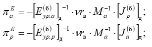 |
(1.2) |
where xк, rк – активная и реактивная составляющие матрицы контурных сопротивлений для системы базисных контуров; Мa, Na – матрицы соединений веток дереве схемы замещения ЭС, соответственно, в узлах контурах [2].
Relationships (1.1) are laws of optimal control, in which feedback coefficients in physical sense – similarity criteria. To implement the control laws, an automatic control system (ACS) for normal ES modes has been developed, the main function of which is to maintain the value of the complex optimality criterion F*, which takes into account the factors of reliability and economy of electric power transportation, as well as its quality, within the established deadband δF* (control actions by control devices are performed after the criterion goes beyond its limits). The system action results in approximation of the current trajectory of power losses change in POS to the optimal one according to the given operating conditions. In addition, implementation of control actions obtained on the basis of (1.1)[2], optimisation of interconnection of main and distribution power grids by voltage losses and levels.
1.2 Improvement of the method of formation of laws of optimal control of normal modes of electric systems with long-distance power transmissions
To compensate for negative influence of non-uniformity of parameters of power grids due to control of switchgear, non-balance EMF must be introduced into circuits, due to which non-balance currents Iнб partially or completely compensate for dummy equalizing currents Iур. In general, for the j–th loop, thus belonging to the base loop system, the non-balance EMF is determined [3]:
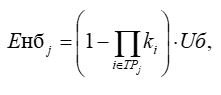 |
(1.3) |
where ki – transformation ratio i–th transformer belonging to multiple transformers j–th loop ТРj; Uб – ES base node voltage.
Dummy equalizing EMF in non-uniform power grids, containing transformer connections and long-distance power transfers as functions of natural and economic current distribution, can be defined by the expression (1.5). Expressions for defining vectors in the presence of multiple balancing nodes in power grids can be represented as follows: [3]:
 |
(1.4) | |
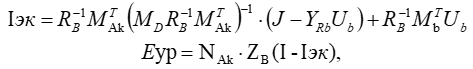 |
(1.5) |
where NAk – matrix of connections of ES branches in its circuits, built taking into account transformer connections and long-distance power transfers; ZB – diagonal matrix of the resistances of the branches of the substitution circuit, in which the branches of the far gears are represented by the constants of the four-pole В; Iэк – vector of economic currents in the branches of the circuit of replacement of electric networks, determined on the basis of calculation of the economic regime of electric networks with long-range power lines; I – current vector in branches, which corresponds to real current distribution taking into account the mutual influence of electric networks of various voltage classes, which work in parallel.
Substituting in (1.5) the expressions (1.4), after transformations and simplifications we get [4]:
| Eзр = E*нбк × Ub − j × (E*нбγUb + Zф.урJ); | (1.6) |
where E*нбк &ndash matrix of relative contour EMF.
It can be seen from (1.6) that the components E*нбγ and Zф.ур are determined by ratio of reactive and active resistances of ES replacement circuit branches [5], coefficients of transformation and coefficients of propagation of wave of far gears (in the form of constant four-pole А). Therefore, the absence of equalizing EMF in closed circuits is characteristic only for electric networks in which the transformation coefficients in the circuits are balanced, all branches correspond to the classical homogeneity condition, and for long-distance power lines a condition of consistency of wave propagation coefficients is provided. Based on the latter, it is almost impossible to ensure homogeneity of power networks with long-range DEPs, and to ensure their operation modes close to economic ones, optimal control of communication transformers with longitudinal-transverse regulation is necessary.
1.3 Features of implementation of automatic power flow control system in ES with decentralization of control function in real time
To implement an automated power flow and voltage control system in electrical systems that provides operational control capabilities, it is advisable to use a classic two-circuit scheme with decentralization of control functions in real time [5]. At the first stage (in the centralized control loop), the reasons for the sub-optimal operation of the POS and the list of available control devices are determined. For this purpose retrospective analysis of mode management results is performed on the basis of short-term planning, and indicators of ES heterogeneity are evaluated. Then, using complete information on POS parameters, matrices of conditionally constant parameters are determined and corrected. Using the developed mathematical models, control laws are adapted in real conditions of operation of control devices, and control devices are ranked according to control priority taking into account reliability and resource of control devices. Zones of insensitivity of local control systems of regulating devices are determined, which makes it possible to establish rational intensity of switching for each transformer and coordinate their operation during operational control so that reduction of power losses is achieved with minimum number of switching.
At the second stage (in the local control circuit), the obtained mathematical models are used to determine the calculated value of control effects and make a decision on their feasibility. Control at the process rate is performed only in the operational control loop. In the external circuit, if necessary, the passive parameters of POS can be corrected. However, such a change is more often carried out at the stage of short-term mode planning after significant changes in loads or significant deviations in the parameters of control devices from planned ones [6, 7].
Such scheme of control system implementation allows to ensure decentralization of part of information functions without loss of principles of centralized control, since during the main time (POS normal operation modes) transformer parameters are controlled on the basis of local parameters, providing conditional optimal system-wide criterion of optimality. Deviation of passive parameters of POS or mode parameters is centrally controlled and, if necessary, individual parameters of models are corrected. Therefore, in essence, centralized operational control of POS modes is implemented using decentralized
subsystems – local control devices at individual transformer substations (power stations)[7].
Automatic control of RP ES and coordination of control actions with operational control is performed using microprocessor device for automatic control and operation (ACAO) of RP (Fig. 1.1). The device can operate in three main modes:
- obtaining the law from the control computer and control according to it (if there is sufficient reliable information on the state of the electric network);
- introduction of the unsealing number from the central control system and its installation on the transformer RTD regulator (in the absence of proper information support or remote control of the power system dispatcher);
- independent operation of the device in the mode of secondary voltage stabilization of the transformer or autotransformer at a given level taking into account the introduced dead zone, or autonomous implementation of counter voltage control.

Figure 1.1 - Appearance of thrust reverser ACUF device (front view)
Operation code is transmitted via communication unit to transfer ACSF of RP from idle state to active state by means of substation ACS. After that, the device checks the RD parameters to identify the extreme positions: the received information is recorded in random access memory (RAM). Depending on the operation code, the device is put into the corresponding operation mode.
If it is necessary to set a certain unsealing of the RTD regulator, first, its number is input from the control computer through the communication unit. In case of mismatch of the new unsealing number with the set number, the sign of the control signal (switching direction of the VSN) is determined. Then, control pulses are supplied to registers of control and monitoring unit; the corresponding relays are closed - and switching begins. The device enters the standby mode of switching completion by monitoring the corresponding channels of the control and monitoring unit of the PLL. After completion of switching, control pulses are removed, parameters of control object are measured, compliance with their specified limits is checked and flame numbers are compared again. The process is repeated until the necessary unsealing is established on the RTD regulator. Any violations of restrictions on parameters (currents, voltages), malfunctions in the operation of the device or control device in the form of messages are sent to the control computer [8].
The application of RP ACUF allows introducing feedback into the POS normal mode control system, monitoring the execution of control actions and evaluating the control efficiency of both individual transformers and the power system as a whole. The latter makes it possible to automate a number of operational control functions and increase the efficiency of using transformer switchgears in the tasks of reducing active power losses in the electrical system.
2 Optimize active capacity flow distribution
Modern electrical networks have natural flow distribution: power flows are distributed along parallel branches according to the complex values of the resistance of the lines that form these paths.
Economical is the flow distribution corresponding to the minimum loss of active power in the network. Economical flow distribution coincides with the natural one that occurs in the design scheme after excluding reactive resistances from it. With economical flow distribution, the power is distributed to the branches only according to the active resistances.
During natural flow distribution, optimization of the mode of the power system is carried out in two directions. The distribution of active capacities between stations is optimized according to the condition of minimum total fuel consumption in the power system. The reactive power of the lines is corrected according to the condition of minimum losses in the network, taking into account the equipment restrictions established by the voltage profile manager and stability conditions. At the same time, the active power flows do not change or change slightly [8].
Unfavorable flow distribution in developed high-voltage networks is associated with heterogeneity of networks – difference in inductive quality. For 110 kV lines, range ID = 1,37–3,34.
The minimum network losses and the corresponding optimal distribution of active power flows would be provided that the inductive QoIs of all lines forming closed loops are equal. Therefore, in order to optimize flow distribution in developed networks, transit flows in lower layer lines need to be reduced several times.
Optimization of natural distribution of power flows in closed networks can be achieved in the following ways:
- longitudinal and longitudinal-transverse adjustment; inclusion of longitudinal compensation units in the circuits; opening of a part of closed network circuits;
- application of the inserts of a direct current (IDC); using controlled transmission lines; use of flexible power transmission.
Figure 2.1 shows sinusoidal voltage (red line) and current (green line) in-phase – there is no phase shift between them (φ = 0°, cosφ = 1) – load is fully active, there is no reactive component. Instantaneous power (blue line) and active power (blue line).
Sinusoidal voltage (red line) and current (green line) have phase shift φ = 90° (cosφ = 0) – the load is completely reactive, there is no active component. Instantaneous power (blue line) and active power (blue line) are calculated with a power factor of 0.
Sinusoidal voltage (red line) and current (green line) have phase shift φ = 45° (cosφ = 0,71) – load has both active and reactive components. Instantaneous power (blue line) and active power (blue line) are calculated from AC voltage and current with a power factor of 0,71.
Figure 2.1 - Phase shift between sinusoidal voltage and current
(animation: 3 frames, 7 repetition cycles, 56 kilobytes)
(Red curve – voltage; green curve – current; blue curve – power; light blue curve – average power; φ – shift angle between phases)
3 Optimal distribution of power flows in closed networks
Optimizing Closed Loop Power Allocation – this is a particular task of optimizing the mode of the electrical network. We assume that constant currents are set at the nodes of the network, that is, the equations of steady state are linear. If constant power is specified in the nodes, then they are determined by nominal voltage [9]:
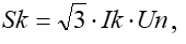 |
(3.1) |
where Sk и Ik – set complex power and current in each node; Un – rated mains voltage.
In this case, the current in the branch kj is defined as follows:
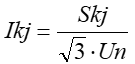 |
(3.2) |
When conditions (3.1) or (3.2) are met, the steady-state equations remain linear, that is, instead of the given complex currents in the nodes, complex powers in the nodes can be used, and instead of currents in the branches – powers in the branches.
Find the distribution of capacity in the network in Figure 3.1, corresponding to the lowest losses of active power, when fulfilling the first Kirchhof law for capacities, provided (3.1). In other words, we define such capacity values S12, S13, S23, which correspond to the minimum loss of active power in the network.
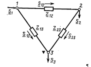
Figure 3.1 - Closed network diagram
When the following restrictions-equalities of the first Kirchhof law are fulfilled for active and reactive capacities:
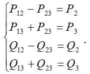 |
(3.3) |
Loss of active power in the network (Fig. 3.1) taking into account condition (3.2) is equal to:
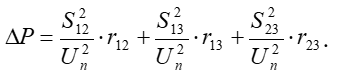 |
Minimum loss condition:
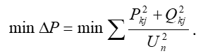 |
(3.4) |
The power loss recorded as (3.4) is the objective function of the network mode optimization task, conditions (3.3).
The constraint system (3.3) contains four equations and six unknown active and reactive power streams in the branches Р12, Р13, Р23, Q12, Q13, Q23.. It has an infinite set of solutions. You can specify any values, such as four threads Р13, Р23, Q13, Q23 and from (3.3) find stream values Р12, Q12, satisfying the first law of Kirchhof. Mode parameters have two degrees of freedom. By changing the mode parameters, you can find their values at which power losses ΔР in the network are minimal [8].
The steady state of a simple closed network is described not only by two complex equations of the first Kirchhoff law, but also by one complex equation of the second Kirchhof law. Regulate and reduce ΔР it is impossible.
We will determine the power flows corresponding to the minimum loss. For this we express Р12, Р23, Q12, Q23 from (3.3) via unknown streams Р13, Q13 and specified loads in nodes:
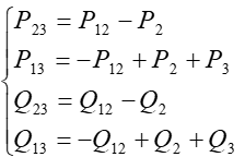 |
(3.5) |
Substitute (3.5) for objective function (3.4) and express losses through two unknown flows Р12 и Q12..
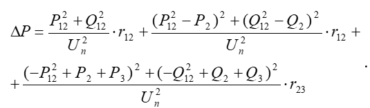 |
(3.6) |
Got an objective function that depends only on two unknowns Р12 and Q12. At the same time, the task of determining the conditional extremum of the function of six unknowns is reduced to finding the unconditional extremum of the function of two variables. As is known, the latter is determined from the condition of equality of zero partial derivatives from ΔР to Р12 and Q12. Having solved the equations, we will finally obtain the following analytical expressions for optimal (economic) power flows Р12 и Q12 [9]:
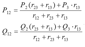 |
(3.7) |
The minimum power loss when implementing the first Kirchhoff law corresponds to the distribution of capacities in a simple closed network with only active resistances. This distribution of capacity is called economic [10].
Conclusions
Reactive power generation affects the voltage mode and power flow distribution of the system. Therefore, the distribution of reactive powers can also be an optimization task.
With complex optimization, any changes in power flows affect the node voltages, which means that the change in active power flows affects the reactive flows and vice versa.
Complex optimization considers the complete task of determining the mode of active and reactive capacities of the system. The electrical network is presented in such a way as to obtain active and reactive power at all necessary branches and nodes. Since changes in the power flows in the network affect the node voltages, it means that the change in the active power flows will affect the reactive flows and vice versa. The main difficulties of complex optimization are that two tasks are combined: optimal load distribution between stations and optimal network mode.
Electrical systems are not optimal considering the consumption of electricity during its production, transportation and distribution. One of the main reasons for the suboptimality of ES states is their heterogeneity. Ensuring optimal operation modes of POS requires the use of appropriate automatic control systems.
The use of the RP ACUF device makes it possible to implement feedback on control parameters in the automated system of optimal control of normal POS modes and provides the possibility of decentralization of individual operational control tasks such as adaptation of monitoring parameters, monitoring of control effects, assessment of the feasibility of controlling individual transformers, etc. The latter makes it possible to increase the reliability and efficiency of using control devices in ES.
List of sources used
- Холмский В. Г. Оптимизация потокораспределения в замкнутых электрических сетях с высокой степенью неоднородности / В. Г. Холмский // Электричество. – 1965. – № 9. – С. 16 – 21.
- Веников В. А. Дальние электропередачи переменного и постоянного тока / В. А. Веников, Ю. П. Рыжов. – М.: Энергоатомиздат, 1985. – 272 с.
- Электрические системы и сети / Н.В. Буслова, В.Н. Винославский, Г.И. Денисенко, В.С. Перхач. – К.: Вища шк. Головное издательство, 1986. – 584 с.
- Справочник по проектированию электроэнергетических систем / Под ред. С.С. Рокотяна, И.М. Шапиро. – М.: Энергоатомиздат, 1985. – 352 с.
- Лежнюк. П. Д. Моделирование компенсации влияния неоднородности электрических сетей на экономичность их режимов / П. Д. Лежнюк, В. В. Кулик, Д. І. Оболонський // Электричество. – 2007. – № 11. – С. 2 – 8.
- Рожкова Л. Д., Козулин В. С. Электрооборудование станций и подстанций. – М.: Энергоатомиздат, 1987. – 648 с.
- Справочник по электроустановкам высокого напряжения / Под ред. И.А. Баумштейна и В.М. Хомякова. – М.: Энергоатомиздат, 1981. – 656 с.
- Электрические системы и сети / Н.В. Буслова, В.Н. Винославский, Г.И. Денисенко, В.С. Перхач. – К.: Вища шк. Головное издательство, 1986. – 584 с.
- Справочник по проектированию электроэнергетических систем / Под ред. С.С. Рокотяна, И.М. Шапиро. – М.: Энергоатомиздат, 1985. – 352 с.
- Идельчик В.И. Электрические системы и сети. – М.: Энергоатомиздат, 1989. – 592 с.