
Abstract
The contents
- Introduction
- 1. Relevance of the topic
- 2. Purpose and objectives of the study, planned results
- 3. Position determination
- 4. Hardware selection
- 4.1 L298 Dual H-Bridge Driver
- 4.2 Step-down module on the MP1584EN chip
- 4.3 Radio module NRF24L01+
- 4.4 ACS712 5A current sensor
- Conclusions
- List of sources
Introduction
Humanity has always been concerned with the question of how to simplify driving, make the car more maneuverable, stable on the road? One solution is to install electronic systems: stability control, braking system, etc. But this did not have such a significant effect. Therefore, the engineers took a different path-the modernization of the steering system. Steering the rear wheels and the theory of cornering.
Even in the presence of the most advanced suspension design, for example, multi-link, when driving at high speed, the inertia of the rectilinear movement of the rear wheels that resist turning becomes a serious factor affecting handling. When turning the steering wheel, when the front wheels start to move left or right in the direction of the turn, the rear unguided wheels try to stay on the same trajectory.
Types of thruster rear suspension and operation schemes In the earliest systems - for example, on tractors of the twenties of the last century, the steering angle was large, up to 15 degrees. With the increase in maximum speed, such large angles had to be abandoned. In modern cars, the steering wheel systems provide a maximum rotation of 5-8 degrees.
he rear thruster suspension is divided into two types — active and passive.
Active thruster suspension.
If the car is equipped with an active steering rear suspension, all four wheels turn at once, responding to the movement of the steering wheel. In modern systems, the force from the steering wheel to the rear wheels is transmitted not mechanically by means of a system of levers, but through the command of an electronic control unit and retracting relays, otherwise called actuators. They move the rear steering rods, similar to those used in the main steering system.
The active thruster suspension operates in two modes. When driving at low speed, for example, in a parking lot or when entering a garage, when the front wheels are turned to the right, the rear wheels turn to the left, and vice versa. This makes it possible to reduce the turning radius by twenty to twenty-five percent. [1]
At high speed, the operation pattern changes. When the front wheels turn to the left, the rear wheels steer in the same direction, but at a lower angle. The electronic control unit monitors the determination of the exact steering angle, taking into account the readings of the angular acceleration sensor, speed sensor and others, forming the optimal algorithm for passing the turn.
Passive thruster suspension. In many modern cars, a simplified system of steering rear wheels is used, which counteracts the inertia of rectilinear movement by using elements in the suspension that have certain physical properties. This type of thruster suspension is called passive. In cars with passive steering, the rear suspension is built according to a special geometry, and, as a rule, with the use of mobile Watt traction. The system is designed so that when passing a bend at high speed, the rear wheels, due to the redistribution of forces in the suspension, tend to steer in the same direction as the front ones. In addition to geometry, the effect is enhanced by the selection of silent blocks of a certain shape and elasticity. This design significantly improves the stability of the car when turning. A passive system of steering rear wheels were equipped, for example, Ford Focus cars of the first generation.
1. Relevance of the topic
The inertia of the rectilinear movement of the rear wheels, especially at high speeds, significantly affects the handling of the car when entering turns. Simply put, they resist turning, trying to stay on their previous trajectory. It is fair to say that the idea itself is not new, and the steering rear wheels have long been used on loaders that are forced to maneuver in confined spaces of warehouses..
Today, many famous automakers have developed and implemented a similar system. All of them have their own name, differ structurally, but the essence remains the same-the rear wheels change their position when cornering, reducing the trajectory and increasing stability. .
The relevance lies in the development of thruster wheels based on an electric drive and a servo drive [2].
Image 1 – Demonstration of the steering gear
(animation: 6 frames, infinite loop of repetition, 80 kilobytes)
2. Purpose and objectives of the study, planned results
The aim of the study is to develop a thruster electric drive aimed at reducing the angle of rotation [3].
Main objectives of the study:
- Mathematical description of the control object.
- Synthesis of the object management system.
- Modeling the operation of the control system and the object in the Simulink environment of the Matlab package.
- When the necessary results are achieved, generate the control system code in C/C++.
3. Position determination
The initial task, and one of the most important for a robotic system, is the task of determining the current position in which the robotic system is located. To do this, the device of the steering wheels must include the software part.
A number of tasks that the management system should solve:
- Planning the angle of rotation.
- After performing the rotation angle at a given speed, it is necessary to develop setting actions for the actuators of the system.
The primary data processing unit receives raw information from sensors about the state of the external environment. In this block, data is collected, grouped, and processed. The output is formatted data transmitted over standard protocols. This is necessary for the convenience of connecting new sensors, and a clear systematization of data, which further facilitates working with data. The information and measurement system for identifying the situation on the basis of the processed data builds a picture of the surrounding world. Sensor data is converted into a set of parameters that other subsystems use to make decisions.
Parameters are generated using a knowledge base and algorithms. It also recognizes surrounding objects and builds a sensory map of the environment. The algorithm database contains mathematical algorithms for building a target sensor map based on data, recognizing the environment and objects (recognizing sound images and images, digital signal processing), calculating the necessary parameters, and verifying the data obtained. The knowledge base represents information about the external environment, laid down at the stage of training and acquired in the process of functioning. Knowledge is organized and updated [4].
4. The choice of hardware
To test and debug the program during the master's work, a radio-controlled model will be used, which will include the following components: L298 Dual H-Bridge driver, Step-down module on the MP1584EN chip, NRF24L01+ radio module, 5A ACS712 Current Sensor, Arduino Uno [5].
4.1 L298 Dual H-Bridge Driver
The L298N is a dual bridge driver for controlling bidirectional loads with currents up to 2A and voltages from 4.5 V to 46 V. The chip is designed to control relays, solenoids, DC motors and stepper motors. The L298N has TTL compatible inputs. In the L298n, there is a separation of power supply for the logic circuit and for the load, which allows you to connect a load with a lower or higher supply voltage than the chip, and also reduces
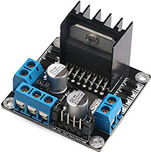
Figure 2-l298n Dual bridge drivern
L298n chips have built-in protection against overheating. The outputs of the chip are turned off when heated to a temperature of about +70°C [6].
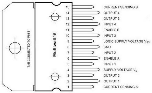
Figure 3-pin Layout of the L298n driver
This driver is already very Mature. The driver runs on outdated bipolar transistors, which in the open state have quite a large resistance. As a result, the driver can not withstand a load of more than 2A with an impressive size, and a radiator is always needed to remove heat.
4.2 Step-Down module on the MP1584EN chip
This module is a simple pulsed DC step-down Converter based on the MP1584EN chip[3]. The module has a low noise level, and this is very important, since it supplies power to the microcontroller and radio module, which are very demanding for stable power supply.
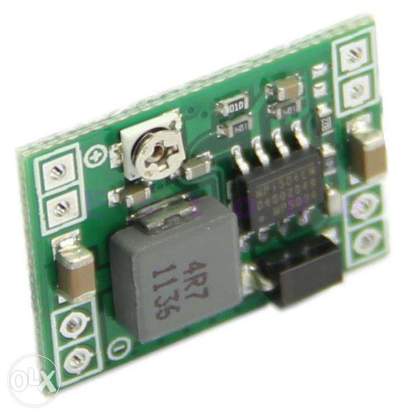
Figure 4-step-Down module on the MP1584EN chip
To adjust the output voltage, the module has a built-in potentiometer [7].
Characteristics of the stabilizer:
- Input voltage: 4.5 V to 28V;
- Output voltage: 0.8 V to 24V;
- Maximum output current: 3A;
In our case, the output current of the module does not exceed 300mA, so you can safely use it without a radiator, there will definitely be no overheating.
4.3 NRF24L01 radio Module+
Radio module for connecting microcontrollers to each other. Operates at 2.4 GHz[5] (resolution-free frequency, which is also used for WiFi), speed up to 2 Mbit, controlled via the SPI interface, power supply 3.3 V (you can use the 3.3 V pin of the Arduino Board). Significantly cheaper than the xbee module, it is well suited for industrial control systems. Range of action - in open terrain up to 100m, within the apartment, through two walls it works confidently, after three-there are signal losses [8].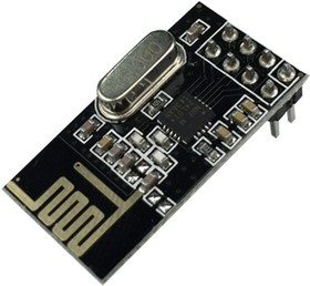
Figure 5-NRF24L01 radio Module+
Specifications:
- Speed up to 2Mbps (configurable 2, 1, 0.25 MB / s;
- 126 communication channels, one-to-many connection, frequency hopping;
- A hardware control error control addressing multi-point communications;
- Low power consumption: 1.9–3.6 V, 1mka in Power down mode;
- GFSK modulation;
- Built-in 2.4 GHz antenna;
4.4 Acs712 5A current Sensor
The acs712 Hall effect DC sensor[6] makes it relatively easy to integrate it into the circuit and start measuring current. The sensor is fully ready for use in the microcontroller and does not require additional components. All you need is an analog input on the microcontroller [10].
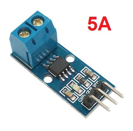
Figure 6-acs712 5A current Sensor
Specifications:
- Current measurement range: up to 5A;
- sensitivity: 185 mV / A;
- maximum bandwidth is: 80 kHz;
- sensor power supply voltage: 5V;
Conclusions
During the development of the thruster wheel device, based on the tasks planned for implementation, a microcontroller was selected, as well as the necessary components for the project implementation.
In the future, it is planned to build and bring all algorithms to full performance.
At the time of writing this abstract, the master's thesis has not yet been completed. Approximate completion date of the master's thesis: June 2021. The full text of the work and materials on the topic can be obtained from the author or his supervisor after the specified date.
List of sources
- Steering the rear wheels [Electronic resource]. – Mode of access: https://www.drive2.ru/b/451627975595524270/
- Simulink. [Electronic resource]. - Access mode: https://matlab.ru/products/Simulink
- WaijungBlockset. [Electronic resource]. – Mode of access: http://waijung.aimagin.com/
- DUAL FULL-BRIDGE DRIVER, Electronics Description, DataSheet № L298N
- The L298N driver. [Electronic resource] / access Mode: http://robotchip.ru/obzor-drayvera-motora-na-l298n/
- Arduino IDE software environment for development under Arduino [Electronic resource] / access Mode: https://arduinoplus.ru/arduino-ide-opisanie-gde-skachat/
- Eclipse (development environment). [Electronic resource]. - Access mode: https://www.eclipse.org/
- Kotsegub P. Kh. Gubar Yu. V., Synthesis of a combined positional electric drive system with a digital IP regulator-Donetsk, 1985.
- CMOS Rail-to-Rail General-Purpose Amplifiers, DataSheet № AD8541_8542_8544
- 1CxemCAR-Android-control the car via Bluetooth. [Electronic resource]. - Access mode: https://cxem.net/...
- Simulink. [Electronic resource]. - Access mode: https://matlab.ru/products/Simulink