
Abstract
This abstract is used as an example, with the permission of Evgeniy Tatolov.
Original: http://masters.donntu.ru/2011/fknt/tatolov/diss/indexe.htm
Содержание
- Introduction
- 1. Theme urgency
- 2. Goal and tasks of the research
- 3. Description of methods for controlling the working surface of a diamond grinding wheel
- 4. Description of the design of a device for profiling the working surface of a diamond grinding wheel
- Conclusion
- References
Introduction
Grinding with a diamond wheel is a rather complex and expensive process that requires competent handling of diamond tools and an understanding of the nature of the wear of grinding wheels. To prevent premature destruction of the cutting surface of a diamond wheel, information is required on the geometric characteristics of the working surface, the intensity of abrasive and bond wear, the deviation of the wheel geometry and its porosity [1].
One of the methods for determining these parameters is the profiling method. This method is a variation of the micrometric wear measurement method.
The profiler measures the value of the so-called "primary wear" - which is taken to be the difference in the height of microroughnesses from the line of depressions to the ridge - measured at the same site at different moments of testing. To measure wear by profilography, profilograph-profilometers are used.
This method is as follows. Profilograms are taken from the same microsection of the investigated surface before and after the test.
On profilograms, the contours of the same depressions remain constant, and the protrusions, due to wear, change their height. Determining the total reduction of the protrusions from the line of valleys, we obtain the value of the primary wear. If it exceeds the height of irregularities, a non-working area of ??the investigated surface is selected as a permanent base from which the measurement is made.
The disadvantage of this method is the impossibility of removing the profilogram before and after testing from the same section, which leads to an error in determining the magnitude of linear wear. This error is the greater, the less is the amount of wear in comparison with the amount of surface roughness [2].
1. Theme urgency
The technological process of grinding is one of the most widespread in mechanical engineering. For example, in the domestic machine building the share of grinding machines is 12%, and in the automotive industry - up to 25%. The grinding wheel, as a cutting tool, has great demands in terms of maintaining the sharpness of the cutting edges and maintaining the required shape of the wheel profile. Diamond grinding is complex and costly a process that requires the competent use of diamond tools and understanding the nature of grinding wheel wear.
Diamond grinding wheels consist of a working diamond layer and a body. The diamond layer consists of a filler, a bond and the diamond powder itself. Therefore, to prevent untimely destruction of the cutting surface of a diamond wheel, information is needed on the state of the working surface of the wheel, namely: the number of grains per unit of the working surface, the density of distribution of the grain tops along the height of the working surface, the height of the working layer, the state of the tops of the diamond grains. Also, the grinding wheel, as a cutting tool, has great requirements in terms of maintaining the sharpness of the cutting edges and maintaining the required shape of the wheel profile. If the strength of the attachment of abrasive grains in the tool is lower than the strength of the grains themselves, then wear occurs due to the chipping of the grains, and the wheel operates in the self-sharpening mode. Self-sharpening is the property of a wheel to remain operational due to the formation of new cutting edges during processing. If the strength of the abrasive grains is lower than the strength of their attachment in the grinding wheel, then wear occurs partly due to brittle fracture and chipping of the grains, and partly as a result of their abrasion by the processed material. Such wear is called wheel bluntness and consists in the formation of wear areas on the surface of abrasive grains and a decrease in the cutting ability of the tool, which manifests itself in an increase in the cutting force up to two times. In addition, uneven wheel wear leads to a change in its profile. The instability of the working characteristics of the grinding wheel, their change during the processing of workpieces leads to a change in the surface quality of the layer of the part. Therefore, it becomes necessary to dress the grinding wheel.
2. Goal and tasks of the research
The purpose of the work is to design a device for automated control of the working surface of a diamond grinding wheel and study its output characteristics
The object of the research is a device for automated control of the working surface of a diamond grinding wheel.
The subject of the study is the control of the working surface by the profilography method
3. Description of methods for controlling the working surface of a diamond grinding wheel
To restore the cutting ability of the grinding wheels, their geometric shape and micro-profile of the working surface, they are periodically straightened, that is, the wheel is brought into a working condition. There are many methods for measuring the degree of wear of a grinding wheel, which are discussed below.
An indirect way to measure the degree of wear of diamond grinding wheels by measuring the cutting force. The cutting forces during grinding affect the quality of the processed surface, and also by the level of forces it is possible to assess the degree of wear of the diamond wheel and promptly resort to the restoration of its cutting properties. The experimental determination of the magnitude and nature of the change in cutting forces during grinding was carried out by many researchers using various measuring instruments. At the first stages of research work, the cutting force was determined by measuring the power developed by the electric motor during grinding using a wattmeter. The magnitude of the tangential component of the cutting force is determined by calculation[1]:
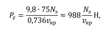
where N e is the effective power in kW developed on the spindle; & nu; cr is the circumferential speed of the circle in m / s. The considered method is simple, but it does not allow measuring the components of the cutting force and is not accurate, since it determines the total power, including the friction losses in the machine mechanisms.
Dynamometric devices can be used to directly measure the component forces. The dynamometer can be made in the form of an elastic coupling with flat radial springs [ 1 ]. Wire resistance sensors mounted on two centers (front and back) of the machine could also be used. Two dynamometric centers allow you to fix the cutting force during grinding at any position of the grinding wheel relative to the workpiece. However, this method is only applicable when setting the part in centers.
A method of non-contact measurement of the wear rate of diamond grinding wheels by measuring the vibration of the grinding wheel [ 2 ]. When the state of the working surface of the wheel changes, vibrations occur, caused both by the vibrations of the grinding wheel itself, and by the mechanisms of the machine.
Displacement in a technological system when vibration occurs is based on measuring the distance between the grinding wheel and the sensor using the capacitive method. The measurement scheme is shown in Figure 1. The capacitive sensor is formed by a metal plate 1 with a device 2 for measuring the initial gap? and the surface of the grinding wheel 3, which is pre-wetted with an electrically conductive liquid. An emulsion or tap water is used as a conductive liquid. When measuring, the grinding wheel is rotated. As a drive, use either a special stand (when installing the grinding wheel on a mandrel), or a machine drive (when measuring directly on the machine spindle). In the presence of relative oscillations between the surface of the wheel and plate 1, the size of the gap ? changes, which leads to a change in the capacity of the gap between the plate 1 and the wet surface of the grinding wheel 3. The change in capacitance with the help of a special amplifier 4 is converted into an electrical signal, which is recorded by the recording device 5 ( see Fig. 1).
This method is a non-contact method for measuring the degree of wear of grinding wheels and almost does not find practical application, since it has a low measurement accuracy. This method is an indirect principle of measuring the degree of wheel wear, characterized by the complexity of processing the measurement results and significant errors, does not allow assessing the unevenness of wear. Inaccuracies in measurement are caused by the dependence of the gap on the state of the liquid, which changes uncontrollably.
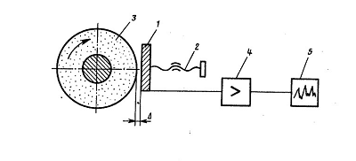
Figure 1 - Scheme of vibration measurements of a grinding wheel.
Photoelectric method for non-contact measurement of grinding wheel wear [ 3 ]. In fig. 2 shows a schematic diagram of a measuring device when measuring the degree of wear of a diamond abrasive wheel.
A photoelectric device for contactless measurement of the degree of wear of a working tool contains an optoelectronic unit, which includes two illuminators 1, an objective 2, a field diaphragm 3, a capacitor 4, two photodetectors 5 and a comparison unit 6; a recorder made in the form of a dial indicator 7; and two reflective elements 8 and 9 in the form of plates.
Reflective elements 8 and 9 are fixed on the side surface of the circle 10, with element 8 located in the wear zone, and element 9 outside it. The device works as follows: before starting the measurements, the circuit is adjusted so that there is no signal at the output of the comparison unit 6, that is, the indicator 7 is zero. As the circle 10 wears out with a decrease in its size, the area of ??the reflective element 8 also decreases, since it is located at the edge of the circle. In this case, the signal that is read by the photodetector, which records the flux value of the element 8, decreases, while the signal received by the other photodetector from the base reflective element 9 remains unchanged. The balance of the circuit is violated, at the output of the comparison unit 6, an output voltage appears, by the value of which it is judged that the wear of the diamond abrasive wheel 10 decreases.
The photoelectric method is a non-contact method, easy to implement, but the main drawback is its relatively low accuracy. The surface of the working tool is used as a luminous flux emitter. To increase the accuracy of measuring the degree of wear of instruments with low reflectivity, the device is equipped with two elements reflecting the luminous flux, one of which is located in the wear zone, and the second is outside it and is the base one. The considered method allows to determine only linear wear, but does not characterize the state of the working surface of the grinding wheel.
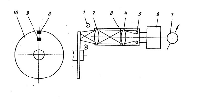
Figure 2 - Photoelectric device for contactless measurement of the degree of wear of the grinding wheel.
Pneumatic method for non-contact wear measurement of a grinding wheel [ 4 ]. A known method of contactless measurement of the degree of wear of diamond grinding wheels using a pneumatic sensor. The proposed method consists in the fact that a nozzle is supplied to the end of the grinding wheel, through which air is supplied under pressure, the flow rate of the supplied air is determined due to the difference in the readings of the length gauge of the pneumatic sensor. The working surface of the diamond grinding wheel is taken as a measuring base. This improves the accuracy of measuring the wear of the grinding wheel during operation.
Optical method for measuring the wear rate of a grinding wheel [ 5 , 6 ]. Most optical methods are based on laser triangulation. The main elements of the setup are a laser diode and a position-sensitive detector (PSD) with an amplifier and two lenses (Fig. 3).
The sensor is mounted on two axes of the stepper drive unit with the ability to move in the direction perpendicular to the surface of the grinding wheel and in the axial direction. This method allows measurements at a circle speed of up to 300 m / s. It is also possible to determine the radial runout.
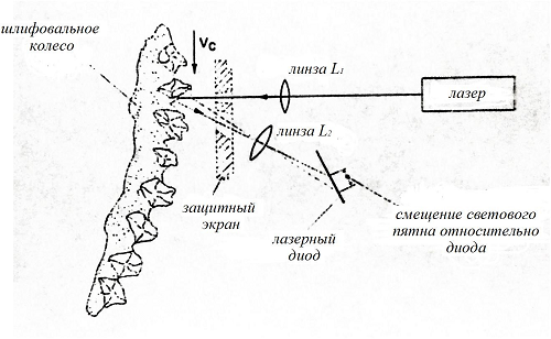
Figure 3 - Optical installation for measuring the degree of wear of the grinding wheel.
Profiling method . This method refers to the experimental determination of the characteristics of the working surface of the wheel. Linear wear of the wheel is measured using a special stationary device at 6 fixed points along the periphery and at three points along the generatrix of the circle with an accuracy of 0.001mm. Measurement of the diameter of grinding wheels less than 50 mm during its operation was carried out with micrometers with an error of ± 0.004 mm. The nature of the wear of diamond grains is investigated using photographs obtained with an MMR metallographic microscope with a magnification of 200x - 500x.
At the department of DonNTU, a special device was developed (Fig. 4) for recording the cutting profile of a diamond wheel on a metal bond with the separation of grains from the general relief of the circle. It is built on the basis of a profilograph-profilometer 4, an electronic unit 3 and a device 2. The information is displayed on the tape of a self-recording device of a profilograph-profilometer 5. On the device 2 there is a sensor of a profilograph-profilometer, which registers vibrations of a rocker arm with a spatula, which moves in accordance with the change circle profile.
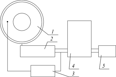
Figure 4 - Block diagram of a device for recording the cutting profile of a diamond wheel.
Here is the wheel rotation drive, consisting of a low-speed engine, a reduction unit and a caprolon drive roller. With the help of the reduced reduction, a very low speed of rotation of the diamond wheel is achieved - 1 revolution in 10 hours for a wheel with a diameter of 200 mm, corresponding to a linear movement speed of 1 mm / min. This speed of tracing the circle corresponds to the speeds of the sensor broach used when profiling the surface of the part. Before recording the profile of the working surface of the circle, the entire measuring device was calibrated. For this, a micrometric clip with a graduation of 2 ?m was used. The profilogram length was at least 15-20 mm of the working surface of the circle.
The wheel rotation drive has the ability to shift in the vertical direction, which allows it to be used for different sizes of diamond wheels. A spatula made of hardened steel is used as a contacting element. Its thickness is 0.05 mm, and its width varied from 0.1 to 0.7 mm, depending on the grain size of the wheel and the research objectives. The diamond grain recording reproduces a distorted image of a set of particles located in the crossed plane of the stylus. The profilogram of the surface of a circle is the plane of orthogonal projections of all structural elements contained in the volume cut off by the edges of the stylus. The analysis of the resulting relief of a circle using a profilogram requires the use of methods of stereological surface reconstruction, which is similar to the analysis of the foil structure in electron microscopy.
The disadvantage of this method is the ability to measure only in the absence of a cutting process and a wheel speed of 0.01 m / s.
4. Description of the design of a device for profiling the working surface of a diamond grinding wheel
Investigation of the position of diamond grains of the RPK is carried out on a measuring complex, which allows registering the relief of the working surface of circles on a metal bond by profilography with subsequent registration of data on a PC. The measuring complex includes a device for fixing a grinding wheel with a unit for its rotation, a set of instruments for a profilometer-profilograph (a device for profiling and an amplification unit), a computer equipped with an analog-to-discrete signal converter, and a display that allows registering the relief of the working surface of the wheels on a metal bond with highlighting relief of grains and bundles. a schematic diagram of the complex is shown in Fig. 5 and its principle of operation in fig. 6.
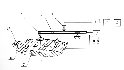
Figure 5 - Diagram of a device for registering the relief of the cutting surface of diamond wheels on a metal bond.
Figure 6 - Principle of operation of the profiler
(animation: 5 frames, 10 repetitions, 44.8 kilobytes)
The measuring complex works as follows. When the circle 9 rotates, the probing needle 3 bends around the profile of the working surface of the circle, vibrating with the rocker 2 relative to the swing axis. These vibrations are perceived by the sensor 1, the signal from which is fed to the input port of the computer 4 through the matching unit and the converter 6 of a continuous electrical signal into a discrete one.
When the probing needle 3 is on the diamond grain 10, the signal from the sensor goes to the matching unit 5, where it decreases to a level of ... 5 V, then it enters the converter 6, in which a continuous electrical signal from the sensor turns into discrete, and then to the computer port 4. At the same time, the signal from the key element 7 is sent to the same port, which gives the code "1" to the signal corresponding to the diamond grain. The computer display shows the relief of the diamond grain with the corresponding color or thick line (Fig. 7).
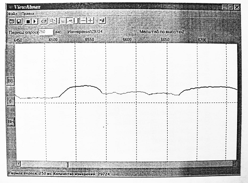
Figure 7 - The window of the program for registering the parameters of the RPC with a fragment of the profilogram of the relief of diamond grains (bold line) and the relief of the bond (thin line)
When the probing needle 3 leaves the grain 10, it hits the conductive bundle 8 and the signal from the sensor continues to go to the computer port through the matching unit 5 and the converter 6 of a continuous electrical signal to a discrete one. At the same time, a signal is sent to the computer port through the key element 7, which corresponds to the metal link with the code "0".
The computer display shows the relief of the metal bond in the corresponding color or thin line.
Thus, the profilogram contains information about the RPK parameters.
To convert analog signals with a value of 0 ... + 5 VV digital codes for recording in a PC, a multifunctional device NVL08 is used. The output differential signal of the electronic unit of the profiler with a value of several volts has a level relative to the ground of about 140 ... 170 V. To match it with the NVL08 input, a device was made, the diagram of which is shown in Fig. 8.
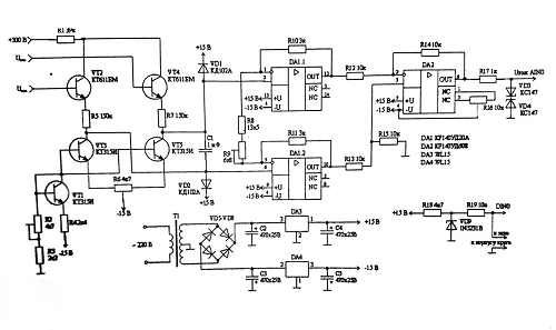
Figure 8 - Schematic electrical diagram of the matching device
A circuit is assembled on transistors VT1 - VT5, which reduces the input voltage. Transistors VT3, VT4, whose bases are connected to the outputs of the electronic unit of the profiler, serve as voltage repeaters, do not disgrace the operation of the electronic unit (the input current is tens of microamperes). Transistor VT1 with resistors R2 i R4 serves to set the currents of transistors VT3 and VT5. These transistors operate in the mode of current sources and provide, together with resistors R5 and R7, a shift of the common-mode signal from high (140 ... 170 V) to approximately zero level with a slight decrease in the useful (differential) signal. Resistor R6 serves to zero the output of the circuit. On operational amplifiers DA1.1, DA1.2 DA2, subtraction of the signals for converting the differential signal into a grounded signal of the required value is realized (Regulation is carried out by resistor R9). To limit the signal at the inputs DA1.1 and DA1.2, diodes VD1 and VD2 are installed. Resistor R17 and Zener diodes VD3 and VD4 serve to limit the voltage at the input of NVL08 to five volts. The device on the elements R18, R19 and VD9 gives a signal equal to one when the needle is on the diamond, and equal to zero when the needle touches the bundle.
To control the launch of the analog-to-digital converter (ADC) of the NVL08 device and to pre-process the measurement results, software has been developed that allows the ADC to be triggered at specified time intervals and to store the results of measurements of the height of diamond grains and bundles along the research line.
The manufactured device for automating the recording of the parameters of the working surface of a diamond wheel to a personal computer allows to drastically reduce the complexity of researching the parameters of the RPC. The RPC relief was assessed by the following parameters: the difference in height of the grains relative to the most protruding grain, the distance between the grains on the working surface of the circle, and the size of the protrusion of the grains from the binder.[7].
Conclusion
From all of the above, we conclude that the most promising is the optical method for determining the characteristics of the working surface of a circle. However, due to the lack of material base and software, for processing the scan result, the practical application of this method is difficult. From an informative point of view, the optical method is most consistent with the profilography method. Using this method, it is possible to evaluate such changes on the working surface as: the number of grains per unit of the working surface, the density of distribution of the grain tops, the height of the working layer, the state of the tops of the diamond grains. Therefore, we will make a device for automated control of the working surface of a diamond grinding wheel based on this method.
When writing this essay, the master's work has not yet been completed. Final completion: June 2021. Full text of the work and materials on the topic can be obtained from the author or his manager after that date.
References
- Маслов Е.Н./Теория шлифования материалов-Москва: Машиностроение, 1974-320 с.
- Авторское свидетельство №444632. СССР. Способ бесконтактного измерения вибраций шлифовального круга/ Болотов Б.Е., Трубников В. В. – №1897640/258; заяв. 28.03.73; опуб. 30.09.75.
- Авторское свидетельство №448366. СССР. Фотоэлектрическое устройство для бесконтактного измерения степени износа рабочего инструмента/ Ронталь Г.Д., Ивашев Ф. Д., Френкель Ш.Т., Вогман Г.А. - №1696795/25-28 ; заяв. 17.09.71; опуб. 30.10.74, Бюль. №40.
- Авторское свидетельство №236026. СССР. Способ бесконтактного измерения степени износа алмазых шлифовальных кругов / Мамедов Д.М., Лятифов Ф. Д., Тренин А.П., Садыхов А.И. - №1053461/25-8 ; заяв. 14.11.66 ; опуб. 24.01.69, Бюль. №6.
- Toenshoff, H. K., Karpuschewski, B., Werner,F., 1993, Fast Sensor System for Diagnosis of Grinding Wheel and Workpiece, 5th Intern. Grinding Conf., Cincinatti, Ohio, USA.
- Toenshoff, H. K., Karpuschewski, B., Hinkenhuis, H.: Regent, C.,1997, Potentiale der Uberwachung und Regelung von Schleifprozessen. VDS-Fachtagung Schleif-technik im Wettbewerb., 09.-10. Oct., Aachen.
- Гусев В.В., Молчанов А.Д. К определению микрогеометрии рабочей поверхности шлифовального круга в статике // Вісник Харківського державного технічного університету сільського господарства. Випуск 10. «ПІДВИЩЕННЯ НАДІЙНОСТІ ВІДНОВЛЮЕМИХ ДЕТАЛЕЙ МАШИН. ФІЗИЧНІ ТА КОМПЬЮТЕРНІ ТЕХНОЛОГІЇ»-Харків:ХДТУСГ.-2002.-С.379-384.