
Abstract
Content
- Introduction
- 1. Relevance of the topic
- 2. Purpose and objectives of the study, planned results
- 3. Research and development overview
- 3.1 Emergency modes of electrical equipment systems
- 3.2 Overview of available technical solutions
- 4. Mathematical description of the model of the investigated object
- Conclusions
- List of sources
Introduction
Continuously growing requirements for the electrical safety of personnel and for economic efficiency in all industries lead to increased attention to the problems of reliable protection of industrial equipment systems, and, as a result, to the electrical protection of motors. Thus, the relevance of the presented study is shown. Proceeding from this, during the operation of a modern control system for an asynchronous motor, optimal parameters of the control law, high reliability and accuracy of frequency control, low cost, and, in addition, maximum energy savings must be ensured. To achieve the required technological parameters, control systems based on microprocessors allow. The aim of the master's thesis is the development of protection systems for industrial equipment, which includes an asynchronous motor based on a programmable microcontroller that meets modern high technological requirements.
The main cause of short circuits in underground electrical installations is mechanical stress. Mine electrical equipment and electric motors have mechanically strong shells that protect their active part from external influences. At the same time, many kilometers of armored and flexible cables, the sheaths of which have insufficient mechanical strength, are operated in underground mines. At the same time, flexible cables laid directly in the faces have the highest accident rate. In case of damage to cables, except for single-phase cables, phase-to-phase leaks may appear, which develop into short-circuit currents. In addition, short-circuit currents can result from damage to the cable by collapsed rock or coal pack, as well as moving downhole equipment or vehicles. In this work, issues related to the theory of short circuits are considered, and the process of a short circuit in a local power grid is modeled, depending on a set of influencing factors.
1. Relevance of the topic
Mine electrical equipment is exposed to humid atmospheres and coal dust. Under operating conditions, coal dust and moisture settle on the surface of electrical insulating parts of electrical equipment, as a result of which leakage currents appear, which, under certain conditions, develop into short-circuit currents. During periodic heating and cooling of mine electrical equipment, dew can form, which will also create conditions for the occurrence of short-circuit. As a result of the observations, it was found that failures of automatic circuit breakers AB due to insulation failure between phases account for 17.6% of the total number of failures.
Currently, the problem of safety in the mining industry is of great importance. First of all, this concerns the operation of coal mines, which are characterized by such specific types of hazards as, for example, methane, increased risk of roof collapses, etc. The most dangerous consequences are usually found in the power elements that are adjacent to the place of occurrence of the short circuit. If the short circuit is at a significant electrical distance from the power source, then the increase in current is perceived by the generators as a slight increase in load. A significant decrease in voltage occurs only near the place of a three-phase short circuit [1].
When we talk about an electrical system, we understand a system that includes an engine. Ninety-five percent of the motors in service worldwide are asynchronous. In comparison with other types of electric motors, asynchronous has the best parameters of reliability, which determines its widespread use in various fields of industrial activity. The choice of electric motors according to their nominal parameters (nominal power, operating mode and design) ultimately affects the smooth operation of the entire electrical system. It is also necessary to comply with the necessary requirements and rules when drawing up an electrical diagram, choosing ballasts, wires and cables, installing and operating the circuit. To ensure the protection of the object under study, it is first necessary to study the operation of electrical systems in emergency modes.
2. Purpose and objectives of the study, planned results
The main objectives of the study:
- Study the emergency modes of the induction motor and the corresponding protection systems;
- Develop models in the Simulink Matlab software environment, which allows simulating overcurrent protection and automatic engine redundancy;;
- Develop protection systems for an AC drive;
- Process and conduct a comparative analysis of the data obtained.
Object of study:electric diagram of the mining area
Subject of study:asynchronous squirrel cage motor
As part of the master's work, it is planned to obtain relevantscientific results in the following areas:
- reliability of the automation system in emergency conditions;
- research of transient processes in motors with frequency converters or thyristor control;
- improvement of overcurrent protection;
- the use of artificial intelligence in the operation of electrical equipment.
3. Research and development overview
The structure of the electrical complex of the treatment area mine is built in accordance with the provisions of regulatory documents and contains a power source - a complete transformer substation (KTP), distribution point of the site (RP) and asynchronous electric motors (M) of consumers (Fig. 1). turn, a district distribution point can be represented by a set of magnetic starters (P), from which, in a radial pattern leads to the induction motors of the respective consumers branched network of flexible cables (GK)[3].
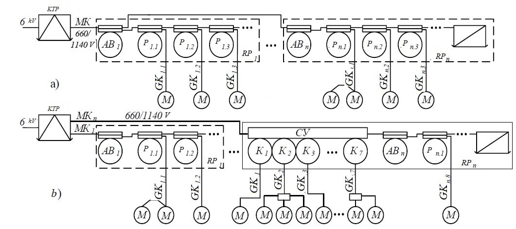
Figure 1 – Typical power supply scheme for the mine treatment area based on the use of starters (a); control stations (b)
Group circuit breaker (AB) is used on the introduction of the district distribution point in order to supply (remove) the voltage to the RP manually and turn it off in automatic mode when condition of loss of voltage in the network, occurrence of a short short circuits in the bay or the presence of an external technological protection command (for example, gas protection). Voltage supply from of the local substation for the input of the group circuit breaker of the distribution point is carried out via the main cable (MK), which is taken as armored or semi-flexible shielded cables.
3.1 Emergency modes of electrical equipment systems
ВThe probability of occurrence of emergency (abnormal) modes for electrical equipment (including the engine) of the system being developed is present even for a properly designed and operated system.
- Emergency modes include:
- multiphase and single-phase short circuits in the motor windings;
- multiphase short circuits in the terminal box of the electric motor and in the external power circuit;
- short circuits to the case or neutral wire inside the engine or in the external circuit – in networks with a grounded neutral;
- short circuits in the control circuit
Short circuits are the most dangerous emergency modes in electrical installations and in most cases they occur due to insulation breakdown or overlapping. Short-circuit currents sometimes reach values that are tens and hundreds of times higher than the values of the normal mode currents, and their thermal effect and dynamic forces to which live parts can damage the entire electrical installation.
Thermal overloads of the electric motor due to the passage of increased currents through its windings:
- when the working mechanism is overloaded for technological reasons;
- especially severe conditions of starting the engine under load and stalling;
- with a prolonged decrease in network voltage;
- wire breakage in the motor winding or loss of one of the phases of the external power circuit;
- mechanical damage in the engine or working mechanism;
- with deteriorating engine cooling conditions.
First of all, thermal overloads cause accelerated aging and destruction of the motor insulation; this leads to short circuits, that is, to premature motor failure.
3.2 Overview of available technical solutions
Circuit elements for overcurrent protection. With different operating modes of the electrical circuit, various abnormal situations are possible, which can lead to the closure of the electrical circuits. It is also possible to single out separately the situations associated with the failure of the phases of the supply voltage, a sharp decrease in the excitation current of DC motors or stopping the movement of the executive body of the motor. These situations lead to a sharp jump in current up to over-permissible values.
It is in such cases of overcurrents that maximum current protection (MCP) is provided. Means of MTZ implementation are fuse fuses, overcurrent relays and automatic switches. Fuses FU are included in each line (phase) of the mains supplying the motor between the mains voltage switch QF and the contacts of the KM line contactor, and can also be included in the control circuit [2, 3]. Figure 2 shows schemes for the implementation of MCP by connecting a relay to a circuit [4].
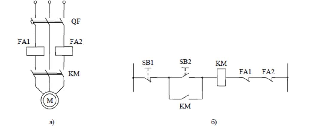
Figure 2 – Relay switching circuits for MСP: a) for an asynchronous motor; b) for relay contacts in the control circuit.
The choice of fuse-link fuses is based on the calculation and selection of them for stable operation in relation to the inrush current in medium and high power circuits. The coils of these relays FA1 and FA2 between the QF switch and the KM line contactor (Fig. 2a). The break contacts of these relays are included in the KM coil circuit of the line contactor (Fig. 1b). When overcurrents occur in the monitored circuits above the FA1 and FA2 relay settings, they open and the motor is disconnected from the network[7].
Technical solutions for protection provide for a certain response time during which the current (and the corresponding thermal overload) of the emergency power connection will be maintained. Considering the danger of an explosion of a methane-air mixture in a mine from ignition at the point of occurrence of a short circuit, a fundamentally important component The protective function should be considered the prevention of open sparks and arcing that could cause this explosion. Acceleration of detection of short circuit mode can be achieved on the basis of measuring the rate of change of the current in the controlled network. This principle can be implemented in different ways, such as by directly determining the slew rate current in the network and comparing this parameter with the controlled value, and indirectly. An example of the slew rate control function current in the network is a fast-acting current protection circuit BMZ, where the response of the VD7 zener diode to the voltage drop value is provided (which is a function of the rate of current rise network) on the load resistor R1 of the bridge rectifier VD1-VD6 (Fig. 3).
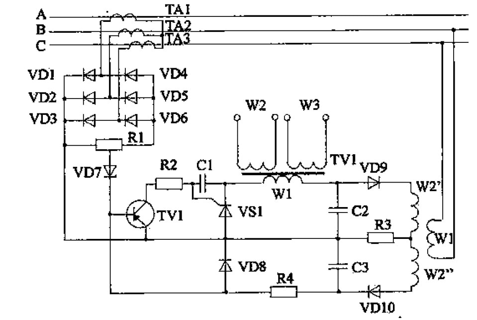
Figure 3 – Scheme of high-speed overcurrent protection of the BMZ type with a reaction function to the rate of current rise in the network.
In another case, the process of increasing the current in a three-phase network can be detected by determining the torque shift coincidence of instantaneous values of currents of adjacent phases (iA и iB, according to fig. 4). The diagram of electrical parameters indicates the presence of a movement in time of this point in the process increase in the current of the three-phase network (the time interval ΔT is converted into a voltage pulse U1 proportional amplitude, which is compared to the reference voltage Uоп). Иso, the emergency state of the network can be detected earlier than the current reaches amplitude level or rms value [2].
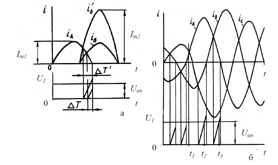
Figure 4 –Diagrams of electrical parameters of the detection device displacement of the moment of coincidence of instantaneous values of currents of adjacent phases three-phase power supply network: a - current overload of the network; b - three-phase short circuit
4. Mathematical description of the model of the investigated object
When building real AC drive systems in control systems include phase converters 3/2 and 2/3 [5]. The first (3/2) - converts three-phase voltages UA, UB, UC in biphasic Ua, Ub, according to expressions:
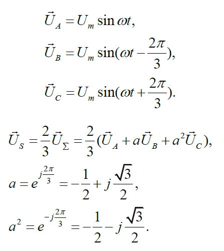
where a is the rotation operator;
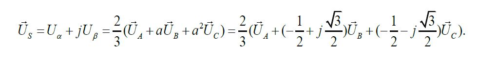
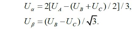
After transforming the equation, we get:
The generalized system of equations for describing an asynchronous squirrel-cage motor has the form:
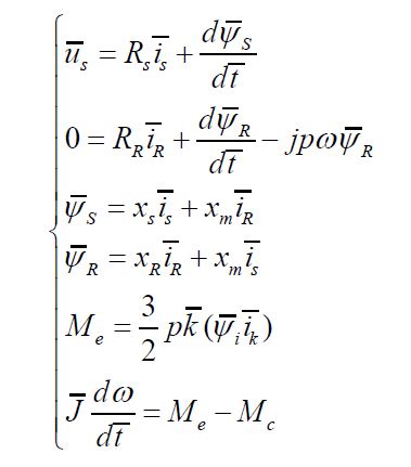
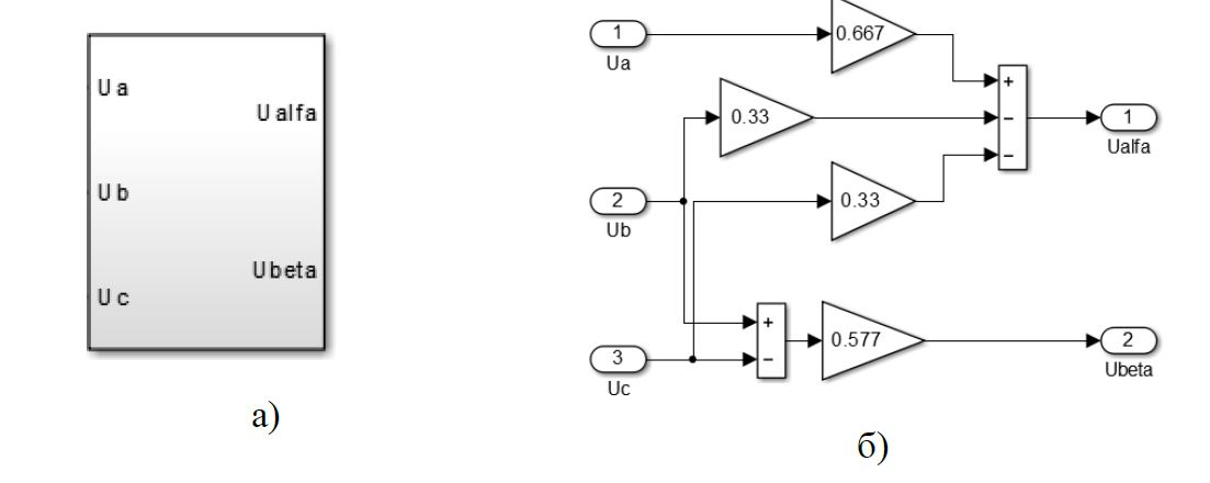
Figure 4 – Converter (3/2): a) conventional graphic designation of the converter; b) model of the converter in Simulink
A simulation model of an induction motor with a resistive load in Matlab Simulink is shown in Figure 5 [6].
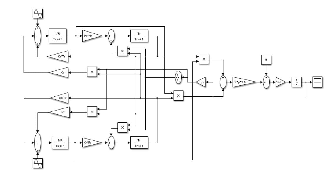
Figure 5 – A simulation model of an asynchronous motor with an active load in Matlab Simulink.
The power channel is implemented using virtual blocks of the specialized SimPowerSystem expansion package, and the control and information channels are built on the basis of the blocks of the main Simulink package.
The MCP model contains a power supply, a converter unit (3/2), an electrical machine unit, a converter unit (2/3), and measuring units.
A simulation circuit of the overcurrent protection of an asynchronous motor is shown in Figure 6. To build graphs of transient processes, the block Scope
.
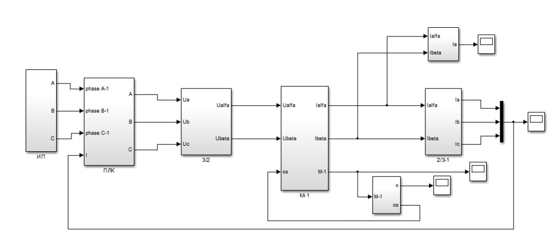
Figure 6 – Simulation model of overcurrent protection of an induction motor
The algorithm of the model is shown in Figure 7.

Figure 7 - Algorithm of the model
(animation: 13 frames, 1 loop of repetition, 118 kilobytes)
Conclusions
In that work:
- the protection of mine section networks from short-circuit currents is considered;
- the short circuit process was demonstrated using the MathCAD computational package;
- significant factors affecting the magnitude of short-circuit currents are determined;
- rational assumptions introduced;
- a mathematical model was compiled, a diagram of a computer model, which made it possible to carry out an appropriate study and obtain relevant data on the short circuit process.
Thus, as a result of mathematical modeling, a transient process of the occurrence of a short circuit in the electrical network was obtained. The developed mathematical model will be used in an adaptive power supply system.
When writing this essay, the master's work has not yet been completed. Final completion: June 2021. Full text of the work and materials on the topic can be obtained from the author or his manager after that date.
List of sources
- Я. С. Риман Защита шахтных участковых сетей от токов короткого замыкания. – М., Недра, 1985г., 88 стр.
- К. Н. Маренич, И. В. Ковалёва Автоматическая защита электрооборудования шахт от аварийных и опасных состояний: уч. пособ. для высш. учебн. заведений / К. Н. Маренич, И. В. Ковалёва. – Донецк: ООО Технопарк ДонГТУ
УНИТЕХ
, 2015. – 214 с. - Б. Н. Ванеев Справочник энергетика угольной шахты. – Донецк: ООО
Юго-Восток, Лтд
, 2001 г. – Т .2,: (Гл. 22-44). – 447 с. В 2 т. - А. В. Андреев Релейная защита и автоматика систем электроснабжения: Учебник для вузов – 4-е изд.перераб. и доп. – М.: Высш.шк., 2006 – 639 с.
- Б. В. Терехин Моделирование систем электропривода в Simulink (Matlab 7.0.1): учебное пособие. - Томск: Изд-во ТПУ, 2010. - 290с.
- Rolf Iserman, Fault-tolerant. Drive-by-Wire Systems. IEEE Control Systems Magazine. October 2002.
- А. И. Белошистов Проблемы защиты от утечек тока на землю распределительных сетей угольных шахт, содержащих силовые полупроводниковые элементы // Белошистов А.И., Савицкий В.Н. Взрывозащищенное электрооборудование: Сб. науч. тр. УкрНИИВЭ. – Донецк: ООО
Юго-Восток, Лтд
, 2004. – С. 78-83.