
Abstract
Content
Introduction
The reliability and efficiency of thermal power plants (TPP) is largely determined by the level of protection of equipment and pipelines from internal corrosion. The main cause of corrosion is the presence of oxygen and carbon dioxide in the water, especially at high temperatures.
Various impurities may be present in the water of the condensate-feed path of the TPP turbine: gaseous (oxygen, carbon dioxide, nitrogen, ammonia), solid (corrosion products of structural materials), natural (chlorides, silicic acids, and others).
Gaseous impurities come mainly from air suckers in the condenser and in the first HDPE (low-pressure heaters) operating at pressures below atmospheric pressure. Corrosion products enter the water as a result of the interaction of structural materials with the water environment, the formation of metal oxides and their transition to water. Corrosion products, as well as some natural impurities (for example, calcium and magnesium), fall into the deposits on the heat transfer surfaces, which leads to a decrease in the heat transfer coefficient and the occurrence of local, most dangerous types of corrosion damage under the deposits. This reduces the efficiency, reliability and safety of the TPP operation. Therefore, during the entire time of using water as a heat carrier, it must be constantly subjected to deaeration.
The economic conditions that have changed recently, in particular, the sharp rise in the cost of fuel and energy resources and the lack of funds to replace worn-out equipment, have made the problem of increasing the energy and economic efficiency of deaeration technological processes very urgent.The efficiency of deaeration depends on such factors as the deaeration surface and the phase contact time, since the process of deaeration of gases from cold water slows down significantly due to the fact that the velocities of water and gas molecules in water decrease with a decrease in temperature.
Currently, the most effective way to improve the efficiency of power plants in the conditions of slow construction of new facilities is to upgrade equipment that has run out of life. In this regard, there is a need for automation of equipment, both the main technology and auxiliary processes.
As a result of equipping objects and processes of thermal power plants with automation systems, microprocessor-based emergency automation and relay protection, a significant economic effect is achieved by optimizing the modes of production, transmission, distribution and consumption of energy, preventing accidents and minimizing damage in the event of their occurrence.
How the system works
Regenerative heating of feed water and basic condensate is the most important method of increasing the efficiency and efficiency of modern thermal power plants (TPP). For regenerative heating, the heating steam used in the turbine is used. Depending on the initial parameters of the hot steam and the number of its selections for regeneration, the increase in the efficiency of the turbine due to regenerative heating of condensate (feed water) can be from 10 to 15%. Thus, regenerative water heating reduces the loss of thermal energy with the spent steam in the turbine unit condenser [1].
Regenerative heating of feed water and basic condensate is the most important method of increasing the efficiency and efficiency of modern thermal power plants (TPP). For regenerative heating, the heating steam used in the turbine is used. Depending on the initial parameters of the hot steam and the number of its selections for regeneration, the increase in the efficiency of the turbine due to regenerative heating of condensate (feed water) can be from 10 to 15%. Thus, regenerative water heating reduces the loss of thermal energy with the spent steam in the turbine unit condenser [1].Despite the separation, the condensate is flow of condensing the working steam from the condenser to the deaerator and feed water flow of condensate, working couple from the deaerator to the boiler, in the future, for the sake of simplicity, both of these flow will be called feed water.
According to the typical thermal scheme of the TPP turbine, the low-pressure heater HDPE-2 is supplied with: feed water from the previous heater HDPE-1, heating steam from the turbine and external condensate from the next heater HDPE-3. Of the heater low pressure HDPE-2 (Fig.1) is heated to a predetermined temperature feed water (heading into next heater IPA-3) and condensation with the drain pump SN inlet feedwater heater next low pressure of PND-3 (Fig.1).
PN type low pressure heater-400-26-7-II (Fig.1) consists of the following main components: water chamber 2, pipe system 4, housing 5. To the compartments of the water chamber, the pipes B, C of the feed water inlet and outlet, respectively, are welded.
For the cylindrical shell are welded pipes of heating steam inlet G, condensation 6, input and output 7 air-steam mixture, and elliptical bottom of the case — a branch pipe of the condensate, which is connected to the drain pump.
Steam is introduced into the housing through the nozzle D, condensed on the pipes of the heat exchange surface, and some of it, together with non-condensing gases (air), is discharged through a semi-circular perforated pipe 7. All condensate is drained to the water level in the housing, and from the bottom through the nozzle in the bottom is discharged from the heater. The heating steam condensate input from the HDPE-3 low-pressure heater is usually carried out through a perforated pipe 6 into the lower part of the housing under the condensate level (Fig. 1).
The features of the HDPE-2 low-pressure heater discussed above, as well as the analysis of its technical parameters and characteristics, allowed us to form a scheme of its information variables and their interaction, which is shown in Fig. 2.1.
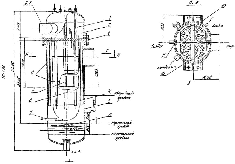
Figure 2.1 – Low pressure heater of the PN type-400-26-7-II
1 – tube; 2 – water chamber; 3 – pipe board; 4 – pipe system; 5 – housing; 6 – input of the heating system; 7 – end pipe of the air-suction device; 8 – guide partition; 9 – support of the pipe bundle; 10 – shields that close the passage of steam past the pipe bundle; 11 – frames for winding the pipe bundle into the housing; D-input of heating steam; B, C-input and output of feed water
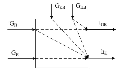
Figure 2.2 – Diagram of the information variables of the low-pressure heater of the TPP
The main controlled variable heater low pressure HDPE-2 thermal power plants, which completely characterize the process of heating the feed water are (Fig. 2):
– feed water temperature at the outlet of the heater tPV ;
– the level of condensate in the heater hK.
To achieve, maintain, or change the controlled variables in the self-propelled gun developed by the low-pressure heater of the TPP, according to Fig. 2, the following control actions are applied:
– the flow rate of heating steam supplied to the heater GN;
– flow rate of condensate discharged from the heater GK.
The required change in the listed control actions is achieved through the use of actuators with regulating bodies – controlled valves with electric drives, which are installed on the corresponding supply pipelines. A control valve or a drain pump can be used to change the flow rate of condensate discharged from the heater.
The main disturbing effect that has a significant effect on the temperature of the feed water at the outlet of the heater tPV is the feed water flow rate GPV, which can vary, within a fairly wide range, depending on the current load on the turbine. In addition to this disturbance, the process of heating the feed water and its temperature tPV are affected by the following disturbances: the temperature of the feed water at the inlet to the heater tPVV; the temperature of the heating steam tN. These perturbations do not have a significant effect on the considered controlled variable tPV, since they change in a fairly narrow range due to their stabilization by other ACS.
The main disturbing influences that have a significant impact on the condensate level in the hC heater are the flow rate of the supplied external condensate GKV, the flow rate of the heating steam supplied to the heater GN and the feed water flow GPV, which vary within a fairly wide range, depending on the current load on the turbine. In addition to these disturbances, the condensate level in the heater hK is affected by the following disturbances: the temperature of the feed water at the inlet to the heater tPVV; the temperature of the heating steam tN, the temperature of the condensate in the heater tK. These perturbations do not significantly affect the controlled variable – the condensate level hK, since they vary in a fairly narrow range.
Thus, taking into account the above analysis, an enlarged block diagram of the concept of building a self-propelled gun with a low-pressure heater of a TPP regeneration system is proposed, which is shown in Figure 3.
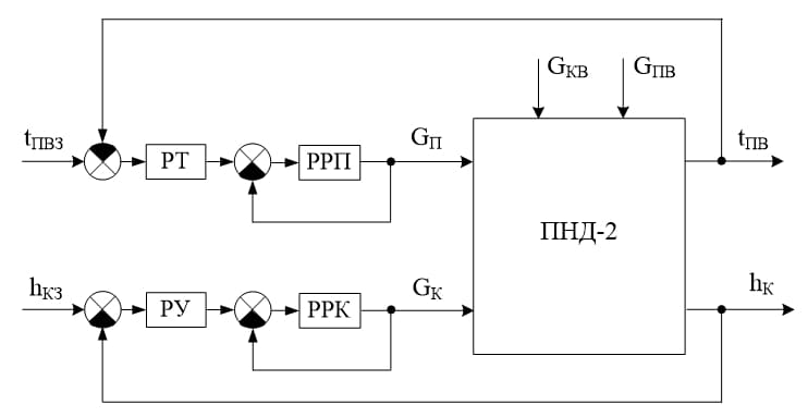
Figure 3.3 – Enlarged block diagram of the ACS construction concept
The stability of the feed water temperature at the outlet of the HDPE-2 low-pressure heater is subject to quite strict requirements – the effectiveness of the further stages of regenerative heating of feed water and the entire TPP regeneration system as a whole depends on this. Therefore, the ACS with the feed water temperature tPV is implemented according to a cascade two-circuit scheme for stabilizing the output water temperature under the influence of the main disturbance – the feed water flow GPV (Fig.3). The internal heating steam flow control circuit GN (Fig.3) is necessary to improve the accuracy of the control process. The algorithm for controlling the feed water temperature in the ACS tPV is implemented by two regulators – an external regulator of the feed water temperature RT and an internal regulator of the heating steam flow RRP (Fig. 3).
ACS level of condensate HCR is also implemented by cascading two-circuit scheme of stabilization of the condensate hK when the effect of the major disturbances of the consumption of heating steam GP, flow supplied external condensate GSQ, the feed water flow rate GPV (Fig.3). The internal condensate flow control circuit GK (Fig.3) is necessary to increase the accuracy and reduce the inertia of the control process. The control algorithm in the considered ACS of the condensate level hK is implemented by two regulators – the external regulator of the condensate level RU and the internal regulator of the condensate flow RRK (Fig. 3).
The effectiveness of solving automatic control tasks and achieving the set goals depends on the selected structural scheme of the ACS. Based on the construction concept (Fig.3), a block diagram of the ACS with the feed water temperature at the heater outlet is proposed, which is shown in Fig. 4.
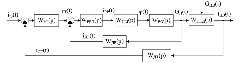
Figure 3.4 – ACS with the feed water temperature at the heater outlet
According to the block diagram (Fig.4), the system of automatic control of the feed water temperature at the heater outlet consists of the following elements: WHDPE(p) – the transfer function of the low – pressure heater; WPO(p) – the transfer function of the regulatory body; WIM(p) – the transfer function of the actuator; WRRP(p), WRT(p) – transfer function of the heating steam flow controller and the feed water temperature controller; WDR(p), WDT(p) – transfer function of the steam flow sensor and the feed water temperature sensor at the heater outlet.
For the necessary change in the control action – the flow of heating steam at the inlet to the water heater GP(t), the ACS consists of a regulatory body WPO(p) with an actuator WIM(p) (Fig.4). Control the current state of basic and additional variables managed by the relevant technological sensors that form a chain of feedback – main: WDT(p) – temperature sensor of feed water and internal: WDR(p) – flow sensor heating steam (Fig.4).
The feed water heater control algorithm is implemented in the form of two regulators: WRRP(p) – internal steam flow controller and WRT(p) – external feed water temperature controller.
Conclusion
The concept of the automatic control system for the low-pressure heater of the TPP turbine regeneration system is proposed, justified and developed. Based on the analysis of the existing principles of building automatic control systems, their features, advantages and disadvantages, it was decided to use the cascade structure of the ACS, as the most suitable for solving the task of automating the considered heater of the regeneration system through the main control channels.
References
1. Шарапов, В.И. Термические деаэраторы / В.И. Шарапов, Д.В. Цюра. – Ульяновск: УлГТУ, 2003. – 560 с.
2. Фрог, Б.Н. Водоподготовка: Учебное пособие для вузов / Б.Н. Фрог, А.П. Левченко. – М.: Издательство МГУ, 1996. – 680 с.
3. Фрог, Б.Н. Водоподготовка / Б.Н. Фрог, А.Г. Первов – М.: Издательство АСВ, 2015. – 510 с.
4. Буров, В.Д. Тепловые электрические станции / В.Д.Буров, Е.В. Дорохов, Д.П. Елизаров и др. – М.: Издательский дом МЭИ, 2007. – 466 с.
5. Костюк, А.Г. Турбины тепловых и атомных электрических станций: Учебник для вузов. / А.Г. Костюк, В.В. Фролов, А.Е. Булкин, А.Д. Трухний – М.: Издательство МЭИ, 2001. – 488 с.
6. Назмеев, Ю.Г. Теплообменные аппараты ТЭС / Ю.Г. Назмеев, В.М. Лавыгин. – М.: Издательство МЭИ, 2003. – 260 с.
7. Шарапов, В.И. Расчет энергетической эффективности технологий подготовки воды на ТЭЦ: Учебное пособие / В.И. Шарапов, П.Б. Пазушкин, Д.В. Цюра, Е.В. Макарова – Ульяновск: УлГТУ, 2003. – 120 с.
8. Лукас, В.А. Теория автоматического управления. / В.А. Лукас – М.: Недра, 1990. – 416 с.
9. Преобразователи давления измерительные Rosemount 2088, 2090P и 2090F. Руководство по эксплуатации. 00809-0107-4108, Ред. CA, 2016 – 160 c.
10. Преобразователь давления (уровня) Rosemount модели 3051. Руководство по эксплуатации. 00809-0107-4001, Ред. JA, 2015 – 220 с.