
Content
- Introduction
- 1 Technological process as an object of automation. Design goal and requirements for the developed automation device
- 2 Critical review of existing solutions and selection of basic automation equipment
- 3 Justification of the direction of automation of a technological unit
- 4 Development of structural and functional diagrams of an automation device
- Conclusions
- References
Introduction
The mine is a complex multifunctional enterprise, the main technological processes of which are the extraction and transportation of minerals. The operation of other machines and mechanisms, not directly involved in these processes, refers to auxiliary and serves to ensure reliable, productive and trouble –free operation of the entire enterprise.
Such auxiliary processes of a mining enterprise include the process of providing mine consumers with heat for heating, ventilation, hot water supply and ventilation of mine workings. The safety and the ability of the entire enterprise to work depends on its reliable operation, since the air supplied to the mine should not have a temperature below +20 оC in order to avoid freezing of the shafts. It is also required to fulfill the sanitary & ndash; hygienic requirements. That is why the sustainable and economical operation of the mine's boiler systems is extremely important.
It is possible to increase the reliability and efficiency of boiler plants by replacing outdated boiler equipment with a more modern one, with higher efficiency, with lower requirements for fuel quality, as well as by introducing a system for automatic control of their operation and protection from emergency conditions and hazards. The scientific project proposes to switch from obsolete layer furnaces to NTKS technology, which will allow operating low –grade fuel, introduce complex automation of technological processes throughout the mine, including the automation of a boiler plant with accepted NTKS furnaces.
Thus, the profitability of the enterprise will significantly increase, it will be possible to burn substandard fuel, and promptly provide the heat needs of mine subscribers. Therefore, the topic of the master's thesis – the development of an automatic control system for the boiler plant of the mine – is extremely relevant.
1.Technological process as an object of automation. Design goal and requirements for the developed automation device
Characteristics of the boiler plant of the mine, heating networks and consumers
At present, three boiler units DKVR –10 –13, one DKVR –20 –13 and two KE –25 –14 have been installed to supply heat to the facilities of the main industrial site of the mine. Boilers No. 1 (DKVR –10), No. 4 (KE –25) and No. 6 (KE –25 – not working, absent) steam No. 2,3 (DKVR –10) and No. 5 (DKVR –20) are water.
In the boiler room, boiler unit KE –25 –14 No. 6 has been under repair since 2004, which has not been completed to date due to lack of funding. Boiler unit KE –25 –14 No. 4 and others also require technical diagnostics and appropriate repairs.
Boiler units are equipped with mechanical furnaces and throwers. The steam boilers are equipped with an economizer to use the heat from the flue gases. Combustion processes are stabilized by blowing fans.
Feed water temperature 80 оC. Deoxygenation of feed water is carried out in a DSA deaeration unit, capacity 50m3. Each boiler is equipped with a smoke exhauster. The chimneys are brick.
In addition, the following groups of pumps are installed in the boiler room:
–Makeup K45 / 55 (3 pcs.) And NSV60 / 40 (1 pc.);
–Saline K20 (1pc.) N – 11 kW, n – 1500 rpm;
–Condensate K20 (1 piece);
–Network D320 / 50 (2 pcs.) N – 75 kW, n – 1500 rpm;
–Nutritional CNSG60 / 132 n – 3000 rpm and CNSG38 / 132 n – 1500 rpm.
The technical characteristics of the boiler equipment are summarized in the table 1.
Table 1 – Technical characteristics of the boiler equipment of the Lidievka mine.
| № п/п | Name | DKVR 10 / 13s steam | DKVR 10 / 13s hot water | DKVR 10 / 13s hot water | КЕ 25/14с steam | DKVR 20 / 13s hot water | КЕ 25/14с steam (not working) |
|---|---|---|---|---|---|---|---|
| 1 | 2 | 3 | 4 | 5 | 6 | ||
| 1 | Nominal productivity, t / h | 10 | 10 | 10 | 25 | 20 | 25 |
| 2 | Steam pressure, Мпа (кгс/см2) | 1.3(13) | 1.3(13) | 1.3(13) | 1.4(14) | 1.3(13) | 1.4(14) |
| 3 | Steam temperature, оC | Saturated 194 | Saturated 194 | Saturated 194 | |||
| 4 | Feed water temperature, оC | 80 | 80 | 80 | 80 | 80 | 80 |
| 5 | Heating surface, м3: | ||||||
| radiation | 47.9 | 47.9 | 47.9 | 97 | 51.3 | 97 | |
| convective | 179 | 179 | 179 | 407 | 357.4 | 407 | |
| common boiler | 206,9 | 206,9 | 206,9 | 498 | 408,7 | 498 | |
| 6 | Volume, м3: | ||||||
| steam | 2.63 | 2.63 | 2.63 | 15.8 | 1.84 | 15.8 | |
| water | 9.11 | 9.11 | 9.11 | 4.21 | 10.6 | 4.21 | |
| 7 | Efficiency, % | 83,5 | 83,5 | 83,5 | 83,5 | 87.9 | 83.6 |
| 8 | Delivery set: | ||||||
| Firebox | TLZM | TLZM | PKK | ТЧЗМ 2.7/5,6 | ТЧЗМ | ТЧЗМ 2–2,7х5,6 | |
| Thrower | RFP–600 (2 pcs) | RFP–600 (2 pcs) | RFP–600 (2 pcs) | RFP–600 (2 pcs) | RFP–600 (2 pcs) | RFP–600 (2 pcs) | |
| Economizer | ЭБ1–300 | – | – | ЭП–330 | – | ЭП1–646 | |
| Smoke exhauster | DN–12,5 N–75квт n–1500 rpm | D–12,5 N–75квт n–1500 rpm | D–12,5 N–75квт n–1500 rpm | DN–17у N–132квт n–1500 rpm | D–17у N–110квт n–1500 rpm | DN–15 N–75квт n–980 rpm | |
| Blower fan | VDN–10 N–11kW n–1500 rpm | VDN–10 N–11kW n–1500 rpm | VDN–10 N–11kW n–1500 rpm | VDN–12,5 N–75kW n–1500 rpm | VDN–12,5 N–55kW n–1000 rpm | VDN–12,5 N–40kW n–980 rpm | |
| Ash collector | BC–2–5х(4+2) | BC–2–5х(4+2) | BC–2–5х(4+2) | BC–2х6х7 | BC–2–7х(5+3) | BC–2–7х(5+3) | |
The preparation of the regeneration solution is carried out in the salt solvent С – 1.0 –1.0 with a diameter of 1000 mm. The boiler room has one salt dissolver and a brine tank with a capacity of 16 tons.
Cleaning of flue gases from each boiler is carried out in a battery cycle unit type BC.
The boiler house uses potable water from the city water supply. The water consumption for feeding the boilers is 31394m3 / year.
Total hardness of source water – 7.0 meq / kg
1st stage of purification – 0.2 –0.5 meq / kg
2nd stage of purification – 0.01 –0.02 meq / kg
The filtering material is sulfocarbon. Salt consumption 4t / month.
The fuel for the boiler room is the coal mine named after Chelyuskintsev
grades D
and DG
with ash content 48.6%, moisture 10.9%, volatiles yield 44%, with a net calorific value of 3557 kcal / hour taken after sorting at the technical complex.
Fuel consumption per year for the boiler house is 14380 t / year.
The boiler house produces steam, superheated water and hot water.
The amount of heat generated is 27259.4 Gcal / year.
At the Lidievka mine steam is used to prepare hot water for baths, heating buildings and structures, and for laundry. Hot water serves as a heat carrier for the air heater on the cage shaft and heating the ABK –2 building.
The temperature of the coolant water is 60 –35 oC. Steam pressure 0.8 –1 kgf / cm2. The steam pipeline d = 200mm from the boiler house to the heat point of the Lidievka mine, located in the central part of the basement of the ABK –1 building, is laid through the air under the rock galleries that transfer the rock from the mine's technical complexes to the loading station to dump trucks. Condensate return pipeline d –100mm. was laid inside the breed galleries.
The heat carrier of the heating system of the ABK building is hot water coming from the boiler house through pipelines with a diameter of 200 mm (supply and return) 800 m long laid through the air on supports of different heights along the railway track together with pipelines with a diameter of 300 m supplying the heating cage shaft. A redundant supply line to the heating coil is not provided.
The ABK heat point – 1 is located in the basement of the building in the block with the pumping rooms for the household – household and fire –fighting water supply. The heat point has five steam –water heaters, a hot water tank for a bath with a capacity of 25 m3, two tanks for collecting condensate with a capacity of 9 m3, three network pumps for supplying hot water for a bath, two circulation pumps of the K 45/55 brand for the building heating system, two pumps CNSG 60 / 90 for returning condensate to the boiler room, steam manifold, switching pipelines with valves. There are no flow control and metering devices. Some steam –water heaters are inoperative.
According to the backup option (depending on the operating mode of the boiler room), hot water for heating the ABK – 1 can be produced in a steam –water heater. PP1 & ndash; 53 & ndash; 7 & ndash; 10 receiving steam from the boiler house through a pipeline with a diameter of 200 mm and a length of 850 m laid through the air under the galleries passing the rock from the mine to the loading complex. The condensate after the heaters is collected in condensate tanks. According to the project, the condensate from the heating station tanks by the pumps CNS 60/90 should be returned to the condensate tanks of the boiler house through a pipeline with a diameter of 100 mm laid along the above rock galleries. The condensate temperature in the heating station tanks is 70 – 80 oC.
Due to the occasional operation of the condensate return pump (it pumps out condensate from the tanks in 10 minutes) and the presence of siphons on the return pipeline (a vertically broken profile), in severe frosts, the water in the siphons managed to freeze, which led to pipeline ruptures. The condensate return pipeline is currently in a semi –disassembled state. There is no condensate return. Condensate from the tanks is used to replenish (mix) the hot water tank for the bath.
Heating and ventilation
The following heated buildings are located at the main industrial site: buildings of the ABK and ABK –1, a mechanic shop, a construction shop, workshops, a canteen and other objects of the surface complex.
The heat carrier for the heating and ventilation system is water with actual parameters of 60 –35 oC and steam with a pressure of 0.8 –1 kgf / cm2. Radiators and registers made of smooth pipes are used as heating devices in the heating system.
The household plant has a respirator, laundry, dryer, showers. The payroll of the mine workers is 217 people. The mine works in 2 shifts.
The laundry is equipped with three centrifuges, washing machines MST 503 (1 piece), KP –219 (1 piece), KP –122 (1 piece), a sewing machine and a drying drum KP –306 (1 piece — not working).
In the maximum shift, 180 kg of dry linen are washed, 500 kg per day.
The number of shifts in the laundry is 2 shifts.
The respiratory room is equipped with a drying chamber, a vacuum cleaner, and a household washing machine. Respirators are handled manually after each change with a chloramine solution.
The clothes dryer is equipped with registers with electric heating.
The showers are equipped with 100 shower nets.
Heating systems of buildings are in satisfactory condition.
In the dining room, the preparation of food sold in the dining room is 100 conventional dishes per maximum shift.
Heating network
Heating networks at the main mine site are mainly laid on high and low supports along the walls of buildings. The section from the administrative building to the dining room is underground. The steam line is laid through the air under the galleries that convey the rock from the mine to the loading point.
The pipelines are insulated with mineral wool products with a covering layer of roofing felt. In many sections of the pipelines, the insulation has been destroyed.
Compensations for thermal expansion are provided by means of U –shaped expansion joints and track turning angles.
As we can see at the moment the boiler units of the mine are equipped with low –performance layer furnaces. As part of the modernization of the boiler equipment of the enterprise, it is recommended to replace them with more economical and convenient in terms of complex automation of the NTKS furnace, which will not only automate the process of obtaining the coolant, but also burn low –grade substandard fuel produced by the mine.
Solid fuel combustion technology in NTKS furnaces
First of all, it is necessary to determine why it is rational to equip mine boiler houses with furnaces of this type. In recent years, the quality of mined coal has significantly decreased, which has led to a decrease in its market value. It also often turns out that the cost of transporting fuel can exceed its cost. In this case, it is irrational to use low –grade fuel far from the mine or to send it to the coal –processing plant. Thus, the most economical option is the consumption of low –grade fuel for the internal needs of the mine. And the maximum heat transfer during combustion of such fuel can be obtained only from NTKS furnaces, which allow burning coal with an ash content of more than 70%. That is why it is rational to equip mine boilers with furnaces of this type.
Fuel in NTKS furnaces is burned in a fluidized bed, which contributes to a significant improvement in the access of oxygen to fuel during combustion, and as a result of intensification of combustion and heat transfer to heating surfaces, as well as more complete combustion of fuel. These factors make it possible to reduce the volume of the furnace space and, consequently, the metal consumption of the boilers, and save 1 –5% of fuel.
A fluidized (fluidized) bed is a collection of polydisperse particles through which fluidizing air is blown at a certain rate sufficient for liquefaction and not exceeding the rate of entrainment of fuel particles from the furnace. In this case, the fuel particles are in a suspended state and intensively mixed throughout the volume of the furnace, which improves the flow of air to all fuel particles and intensifies the combustion process[1].
A diagram explaining the operation of a low –temperature fluidized bed furnace is shown in Figure 1.
Blast air for bed liquefaction is supplied to the furnace through the air distribution grate by means of a high –pressure blast fan VMC –6 at a speed sufficient for bed boiling (2.5 –4 m / s). The coefficient of excess air supplied to the furnace for 1 kg of coal is 1.2 –1.6, theoretically required for fuel combustion.
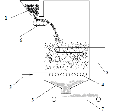
Figure 1 – Installation of NTKS: 1 – fuel, 2 – fluidizing air, 3 – ash, 4 – air distribution grid, 5 – submersible heating surfaces, 6 – fuel supply system, 7 – ash unloader
The air distribution grid is the main part of the equipment that provides the combustion method in the NTKS. It provides uniform distribution of the fluidizing agent throughout the entire section of the furnace, as well as uniform distribution of fuel and removal of ash from the bed.
The air distribution grille is a set of pipes welded to the air distribution manifold, to which nozzles with caps are welded, which have holes along the perimeter through which air is supplied to the furnace under high pressure.
Fuel is supplied to the furnace from the fuel bunker using a drum –type spreader ZP –600. Moreover, the fractional composition of the fuel should not exceed 13 mm, which follows from the conditions of fluidization of the bed. The required fractional composition of the fuel is provided through the use of a crusher or a screening unit at the stage of fuel preparation, and fuel with a fraction of up to 13 mm is supplied to the coal bunker.
For uninterrupted and trouble –free operation of low –temperature fluidized bed (LFB) furnaces, it is of great importance to maintain the temperature and height of the bed, which in the process of coal combustion is ensured by the timely removal of the accumulated ash.
The most reliable and trouble –free operation were the swing –type unloaders, consisting of a table with an opening for ash spilling, a crank mechanism, a gearbox and an electric motor. The practical implementation of the low –temperature combustion method is associated with overcoming a number of technical difficulties, the most significant of which are the need to prevent slagging of the layer and increased requirements for fuel preparation (the diameter of fuel particles must be 6 –13 mm).
It is most expedient to provide the bed temperature equal to 800 –850? С. Temperatures close to 800 ° C are determined by the most optimal conditions for the binding of sulfur oxides released from the fuel during combustion, dolomite and limestone, as well as alkaline earth metals contained in the ash of the fuel. At these temperatures, nitrogen oxide emissions are also reduced.
Removal of slag from furnaces with LTS does not cause difficulties, since slag pieces, due to their high density, sink in the fluidized bed and collect in the lower part of the furnace. Slag removers must ensure the required tightness.
The main condition for the reliable operation of the furnace with NTKS is the uniform distribution of air over the entire area of ??the furnace. This is achieved by installing air supply caps with 6 –8 holes for the passage of air, the velocity of which during the passage of the layer (combustion mirror) is 0.5 –4 m / s. The design of the cap should prevent slag or fuel from entering the air supply ducts when the air supply is cut off. Depending on the bed height, air should be supplied to furnaces with NTKS under a pressure of 3 –10 kPa.
To achieve this pressure, high –pressure fans are used, for example, VMC 6. The coefficient of excess air supplied to the furnace per 1 kg of coal is slightly higher than for layer furnaces, and amounts to 1.2 –1.6 theoretically required.
Due to the fact that the size of the pieces of fuel supplied to the furnace does not exceed 13 mm, and the air velocities in the bed are increased, many small particles of unburned fuel are carried away with the flue gases to the gas treatment, where they are captured and returned to the furnace for afterburning [1].
The combustion of fuel in a low –temperature fluidized bed has a number of advantages over traditional layered combustion of fuel. The most significant benefits:
– in a low –temperature fluidized bed it is possible to burn low –reaction and high –ash coals with ash content up to 75 –80%, which is unattainable with other combustion methods. This is due to the stabilization of the fuel combustion process due to the presence in the layer of a large amount of solid particles heated to 800 –9500C with a high specific heat capacity;
– simplifies the design of combustion devices and the possibility of their mechanization and automation;
– the efficiency of boilers increases when burning low –grade and high –ash coals;
– the working conditions of the service personnel are improved due to the possibility of automating the combustion process, maintaining the combustion temperature of the fuel below the beginning of the softening of ash, which ensures its non –concomitant combustion;
– the release of service personnel is achieved on fire –tube boilers of outdated design.
Consider the goals and objectives of the master's thesis.
During operation of a boiler unit equipped with a low –temperature fluidized bed (LTS) furnace, solid particles can sinter in the bed due to an increase in temperature above the critical one or extinction of the bed due to a decrease in temperature below the permissible limit [1]..
These situations are emergency and entail significant equipment downtime, additional costs of labor and materials.
Consequently, an important function that ensures trouble –free operation is operational control and forecasting of the parameters of the object, which can be used to judge the possibility of an emergency.
Also, to ensure the cost –effective operation of the boiler unit, it is necessary to regulate its performance depending on the actual heat demand, which leads to a decrease in fuel costs.
Thus, the goal of scientific work is to increase the efficiency and safety of the boiler unit through the comprehensive automation of its work.
The system being developed must meet the following requirements:
–To monitor the main technological parameters of the boiler unit on –line;
–To adjust its performance according to the task received;
– have appropriate signaling, as well as external communication devices with the operator;
– be constructively implemented on a microprocessor unit;
– have adequate protection against moisture and dust penetration, as well as climatic design.
2. A critical review of existing solutions and the choice of basic automation equipment
In industrial practice, at the moment, when operating NTKS boiler houses, they use devices of the Kontur
system [8]., the principle of operation of which is discussed in detail below.
The automatic control system of the combustion process is equipped with devices of the Kontur
system , which provide control of the solid fuel supply to the furnace depending on the boiler load with correction for the temperature in the fluidized bed, maintaining the optimal ratio of fuel and air, maintaining the required stable vacuum in the furnace. Let us consider its work in more detail below.
The Fuel
control loop (See Fig. 2.2) contains a sensor (pressure gauge 56), a regulator (5c) and starting equipment (NS / KM11) to control a single –turn electric motor of the fuel supply control mechanism (5d – an actuator).
Automatic adjustment of the fuel supply to the furnace is carried out according to signals from the steam pressure sensor (in the case of a steam boiler), which is an electric pressure gauge RT / 56 with a remote signal (readings) transmission to the RSK / 5v regulator. The pressure gauge converts the steam pressure from the drum of the steam boiler into an alternating current electrical signal.
The Air
control loop consists of a sensor (pressure gauge 216), a regulator (21v), starting equipment (NS / KM12) for controlling a single –turn electric motor (21d) of the guide vane rotation mechanism in the pipe supplying the blower fan.
The correcting signal to the regulators 5c and the twenty –first comes from the correcting device 5d (differential), which, in turn, receives a signal from the sensor 5a (thermocouple). The corrective link acts as a feedback.
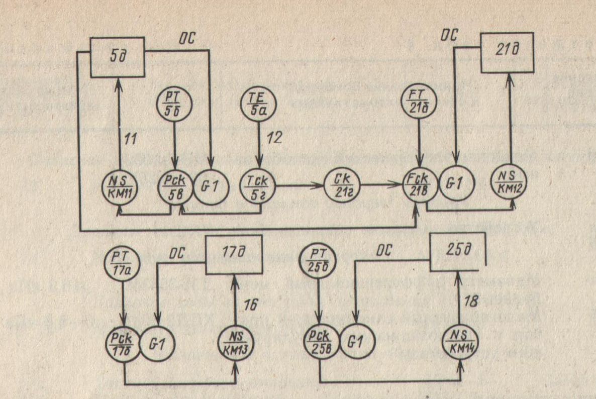
Figure 2 – Scheme of automatic regulation of the combustion process
The vacuum regulator 176 maintains a constant vacuum with high precision. The vacuum pulse is taken in the upper part of the furnace by a sensor (traction meters) 17a, which converts the vacuum into an electrical signal supplied to the regulator 176. From the regulator, the signal is sent to the starting equipment (NS / KM13) for controlling the single –turn electric motor of the actuator 17d for turning the guide vane installed in the pipe, supply smoke exhauster. When the vacuum in the furnace changes by an amount exceeding the insensitivity of the regulator amplifier, the electric motor of the actuator 17d moves the guide vanes of the smoke exhauster until the specified vacuum is restored.
Adjustment Water level
is carried out by the regulator 25a, which receives a pulse from the level sensor 256 and acts on the actuator 25d, which is articulated with a controlled valve on the feed water pipeline. A pressure gauge 256 serves as a level sensor, connected to the drum through an equalizing tank 25a.
The automation scheme is controlled by thermotechnical control (see Fig. 2.2): boiler ignition temperature (2a, 26), fluidized bed temperature (by, 36), flue gas temperature (1a, 16), air pressure after the blowing fan (9), pressure steam (11), pressure of liquid fuel in the inlet and outlet pipes of the fuel pump (12, 13), vacuum in the boiler furnace (18), vacuum in front of the smoke exhauster (20), water level in the boiler drum (246), fuel level in the bunker ( 26a), water temperature before and along the cooling circuit (6a, 8a), water pressure along the cooling circuit (15, 16), water flow through the cooling circuit (22a, 226, 22b), fluidized bed resistance (31a). The protection circuit provides an automatic shutdown of the fuel supply in the event of emergency modes, an increase in the temperature in the fluidized bed, an increase in the blast air pressure, a decrease in the vacuum in the boiler furnace, a deviation of the water level in the boiler drum, an increase in the water temperature along the cooling circuit, a deviation of water pressure along the cooling circuit, reduction of water consumption through the cooling circuit.
The scheme provides for storing the cause of the accident. Emergency stop of the boiler is accompanied by a light and sound alarm.
The block diagram of the regulation of the parameters of the boiler equipped with a furnace NTKS with regulators R –25 is shown in Figure 3.
Each control loop contains a P25 regulating device. Control devices P25 are intended for use in automatic regulation and control circuits of various heating devices that perform the following functions:
–Summation of signals from information sources (sensors of primary devices), introduction of a task signal and amplification of a deviation signal;
– formation of the PI – regulation law together with the constant speed actuator (together with the differentiator, the formation of the PID – regulation law);
–Shaping DC and AC signals to control the actuator;
–Manual control of the actuator;
–Conversion of a signal from a differential – transformer position sensor of an actuator into a DC signal.
The output circuits of the devices allow you to control various switching equipment with signals of 24 V DC or 220 V AC, as well as control actuators equipped with electric motors with symmetrical windings MEO –73.
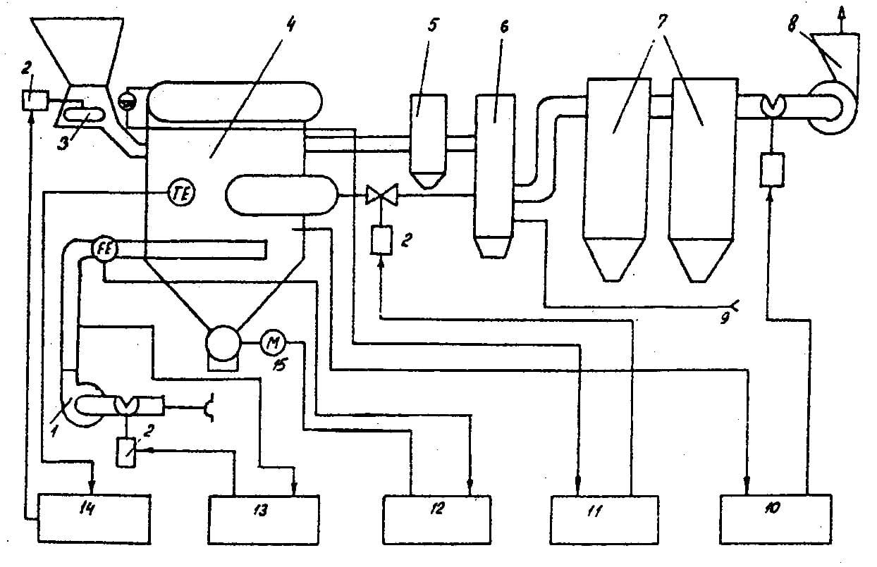
Рисунок 3 – Структурная схема регулирования параметров котла оборудованного топкой НТКС: 1 – дутьевой вентилятор, 2 – исполнительный механизм МЭО; 3 – забрасыватель топлива; 4 – котёл; 5 – прямоточный циклон (циклон возврата уноса); 6 – экономайзер; 7 – циклоны первой и второй ступени очистки дымовых газов; 8 – дымосос; 9 – подпиточный трубопровод; 10,11,12,13,14 – регуляторы соответственно разрежения, уровня, выпуска шлака, расхода воздуха и топлив
The main problem of the existing automation system is that although the regulators keep the parameters within the specified limits, they are not interconnected. Therefore, we can conclude that the regulation of parameters may not be optimal (the connecting link between the control loops is a person).
However, as follows from the description of the scheme, the regulation of technological parameters is carried out along several open circuits, without taking into account the state of other indicators. So, it is impossible to achieve high quality control of the technological process, quickly and economically provide the required performance.
Based on the experience of the Kontur
system, during further design, it will be expedient to replace the blast air flow rate and bed temperature controllers with one microprocessor device. It is expedient and economical to leave the contours of the stabilization of the vacuum above the furnace and the height of the NTKS on the basis of the KONTUR system, as well as the technological sensors and actuators of technological devices.
To measure the exhauster vacuum, a DT2 –50 type differential meter is used. The secondary converter of the KSDZ type operates according to a differential transformer circuit with an output voltage of 0 ... 0.5 V AC.
The air consumption in the furnace is measured with a differential pressure gauge, type DM3583M. The maximum signal level of the converter is 0.5 VAC. The pressure drop in the bed and above the bed, to control the bed height, is measured with a differential pressure gauge type DM3583M with a secondary transducer similar to an air flow sensor.
The temperature of the CO is measured by a thermoelectric converter of the TXA 706 –02 type [3] with a sensitivity of 30 mkV / 0C and an inertia of setting readings of 60 seconds.
The coolant temperature is measured by a thermoelectric converter of the ТХК – 0515 type [3] with a sensitivity of 24 mkV / оC and an inertia of 60 seconds.
3. Justification of the direction of automation of a technological unit
The analysis of the state of the matter showed that at the moment there is no effective system of integrated automatic control of the productivity of the mine boiler plant, which would improve its technical and economic indicators.
Consider below the methods for controlling the performance of the NTKS boiler unit.
The simplest method of regulating the heat load of the boiler is by changing the fuel supply to the layer with the subsequent change in the temperature of the NTC layer and, accordingly, measuring the heat transfer to the heating surfaces in the boilers. The application of this method, however, is limited by the narrow range of operating temperatures of the NTC. With a decrease in the temperature of the NTC below 700оC, the degree of fuel burnout and the intensity of combustion sharply decrease, at temperatures above 950оC, there is a threat of slagging of the furnace. Therefore, the degree of regulation by this method depends significantly on the temperature of the heat –receiving surface. In low pressure hot water boilers, the temperatures of the heating surfaces are ~ 950 оC and a change in the temperature of the bed in the range of 700оC –950оC leads to the regulation of the heat flow by 20%. Typically, this method is used to regulate the heat load of small boilers used in mine boiler houses. The condition for applying the method with the maximum efficiency is the maintenance of an excess of air in the furnace corresponding to the minimum value of heat losses, which is not carried out during the operation of the currently existing boilers.
Another way is to regulate the load by changing the speed of the blast air.
Regulation of the blowing air speed leads to corresponding changes in the porosity and height of the combustion chamber, and in case of partial immersion of tube bundles in the combustion chamber, the value of the immersed heating surface. In this case, due to the large values ??of the heat transfer coefficients of the layer, the thermal load of the boiler changes significantly. With a decrease in thermal stress and a corresponding decrease in fuel supply, operation in the range of 50 –100% of the nominal heating capacity is possible. To reliably regulate the value of heat output by this method, it is necessary to know the dependence of the degree of expansion of the NTCS, stratification and carryover of the layer, as well as the dependence of heat exchange characteristics and the rate of pipe erosion on the heat load of the unit.
In a number of small boilers with NTKS furnaces, a thermal control system is implemented due to the expansion of the bed, in which the submerged tube bundle removes about 50% of the heat of combustion of the fuel. A change in the area of ??the submerged heating surface during the combustion of ash fuels when sulfur –absorbing additives are introduced into the furnace can be achieved by changing the mass of the layer material (by changing the rate of unloading of particles and (or) short –term shutdown of the additive system). It should be noted that this method is applicable only in boilers with submerged heating surfaces, which have not found wide application due to their increased wear due to the abrasive properties of the layer material.
Given the complexity and versatility of the ongoing processes (the need to analyze the process), it is advisable to operate the furnaces in an automatic mode. Hence, we come to the conclusion that instead of separate control loops, a single –chip micro –computer or a finished computer with devices for matching, switching, decoupling, etc. should be used. The following requirements must be put forward for the automation device being developed:
–Control of such technological parameters: temperature of the STC, solid fuel consumption, speed of blast air, layer height, rarefaction in the furnace;
– regulation of the furnace productivity, the solid fuel consumption and the speed of the blast air;
– development of a device based on a microprocessor with the obligatory presence of a remote communication interface;
– visualization of the technological state of the combustion chamber furnaces;
– constructional version not lower than IP54, climatic version
4. Development of structural and functional diagrams of an automation device
On the basis of the developed algorithm for the operation of the automatic control system of the boiler productivity, its structural diagram was developed, shown in Fig. 4..
Figure 4 – Block diagram of the automation block
(animation: 9 frames, delay 1000 ms, 117 kilobytes)
In the above diagram, the following designations are adopted:
– DT NTKS – temperature sensor NTKS;
– DRTT – solid fuel consumption sensor;
– DSDV – blast air speed sensor;
– DCT – sensors of the end positions of the MI to control their extreme positions
– MPB is a microprocessor unit that regulates the performance of the NTKS according to the received task according to the current technological information, the value of the NTKS temperature at a given level, adjusting other technological parameters. It includes:
– BGR – block of galvanic isolation. converts control signals to the actuators of the IM of the solid fuel dispenser and the blower fan according to the control commands from the MC.
– PSU – power supply unit.
Figure 5 shows a functional diagram of an automation device, the operation of which is as follows.
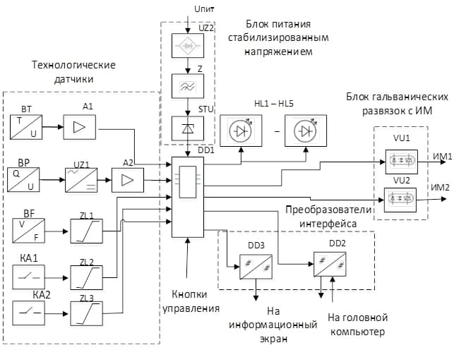
Figure 5 – Functional diagram of the automation device
The information signal from the temperature sensor NTKS VT (thermocouple) through amplifier A1 is fed to the input port of the microprocessor device DD1. Similarly, signals from the following process sensors are sent to other ports of the microcontroller: BF – solid fuel flow sensor (tachogenerator) through the ZL limiter, 1ВР – blast air flow sensor ВР – through the UZA1 rectifier; KA1 and KA2 are sensors of the extreme positions of the actuators (limit switches) through the amplitude limiter ZL2 and ZL3, respectively. Also, the setpoint values ??are supplied to the microcontroller port from the head computer (or from the keyboard by the operator) through the DD2 interface converter.
In accordance with the software, the microprocessor device DD1 generates control signals of the IM of the solid fuel dispenser and the blower fan of the IM1 and IM2 blast air using the seven –story optocouplers VU1 and VU2.
Microcircuits DD2 and DD3 are designed to amplify the signals of the RS485 interface. Through DD2, there is a duplex exchange of information with the operator's external computer (the so –called highest level of the ACS), the signal code pulses are sent to and from the personal computer in the duplex communication mode. Through DD2, information is displayed on the information board. Local control is carried out from the control buttons. Additional LED indication of the control circuit operation is implemented using light diodes HL1 ... HL5.
The circuit is powered from a 380 V mains through a stabilized voltage power supply, which consists of a UZ2 rectifier, a Z filter and an STU stabilizer.
conclusions
As a result of the research work, the boiler plant of the mine was analyzed as an object of automation. The main technological features of the furnaces actually used at the mine were outlined, and, due to their shortcomings, the project proposed replacing them with more highly efficient and economical NTKS furnaces.
The goal of the work was formulated, which was to increase the efficiency of the boiler house through its comprehensive automation, and also formulated the requirements for the automatic control system.
Taking these requirements as a basis, circuitry solutions were proposed for the automatic control device for the performance of a boiler with a NTKS furnace in terms of solid fuel consumption and blast air speed.
When writing this abstract, the master's work has not yet been completed. Final completion: June 2021. The full text of the work and materials on the topic can be obtained from the author or his manager after that date.
References
- Сжигание угля в кипящем слое и утилизация его отходов/ Ж.В. Вискин и др.–Донецк:Типография
Новый мир
, 1997. –284 с. - Сидельковский Л.Н., Юренев В.Н. Котельные установки промышленных предприятий: Учебник для вузов. – 3–е изд., перераб. – М.:Энергоатомиздат, 1998. – 528 с.: ил.
- Чистяков В.С. Краткий справочник по теплотехническим измерениям. – М.: Энергоатомиздат, 1990. – 320 с
- Гутников В.С. Интегральная электроника в измерительных устройствах.–М.:Энергоатомиздат,1988
- Лавриненко В.Ю. Справочник по полупроводниковым приборам – К.: Техника, 1984
- Голубцов М.С. Микроконтроллера AVR: от простого к сложному. – М.: Cолон–пресс, 2003.
- Интернет–ресурс. http://radio–uchebnik.ru/microbase/
- Батицкий В. А., Куроедов В. И., Рыжков А. А. Автоматизация производственных процессов и АСУ ТП в горной промышленности; Учеб. для техникумов. – М.: Недра, 1991.