
Abstract on the topic of graduation work
When writing this essay, the master's work has not yet been completed. Final completion: June 2021. Full text of the work and materials on the topic can be obtained from the author or his manager after that date.
Contents
- Introduction
- 1.Methods of geometric modeling
- 2.Complex of universal analytical methods for modeling complex geometric objects and their transformations
- 2.1 Method of smooth conjugation of curves and planes
- 2.2 Method of rotation of a geometric object around an axis passing through a given point in space
- Conclusion
- List of sources
Introduction
Mathematical modeling of physical and mechanical processes and engineering structures is often associated with the need to create geometric models. With their help, it is possible to determine the image of an existing or projected object, carry out a numerical experiment corresponding to the formulation of the problem, and carry out the necessary corrections. A geometric model in a broad sense is a set of formal descriptions of the object under study and the corresponding visual image, presented in spaces of different dimensions. In connection with the development of modern methods of computer modeling, the formal description is primarily the numerical modeling of geometric objects of the surrounding world. Moreover, their diversity is created using basic geometric elements: points, lines and surfaces.
1.Methods of geometric modeling
Geometric modeling is currently developing in two directions. The first direction is numerical methods in CAD and computer graphics problems. The modern stages of CAD implementation are characterized by the transition from flat to volumetric modeling. The accuracy of the geometric object model is ensured by the accuracy of the transformation of the base primitive. For plane modeling, the main objects of modeling are lines, arcs, polylines and curves, including Bezier curves, splines, rational curves. Basic transformations based on them are extension, cropping and joining. In volumetric modeling, the main objects are closed contours. In this case, motion surfaces, ruled, Bezier, Koons surfaces are used. The main operations are Boolean: union, addition, intersection, as well as rotation and translation transformations. There is a concept of a base surface, from which one or another transformation is carried out during the modeling process. As a result, by means of CAD, the designed object is numerically constructed from geometric bodies, called graphic primitives, which can be transformed by one or another software means. There is no analytical presentation of the new forms obtained by such transformations.
The second direction of geometric modeling is represented by works where geometric objects are specified in an analytical form. More than 500 analytically specified surfaces of 38 classes have been identified, which can be used in solving various problems of science and technology. Analytical methods for representing geometric objects are highly accurate. Various forms of describing objects and their transformations are possible – vector, operator, tensor and other forms, which allows you to specify each point of a geometric object and perform arbitrary transformations in an analytical form. At the heart of the classification of analytical surfaces, the methods by which these surfaces are obtained have an essential role. There is a large class of surfaces that are obtained by transforming the rotation of a plane curve around the Oz axis. Another extensive class of surfaces is obtained by transforming the translation of a curve in a certain direction, so that one point of it slides along another curve. More complex transformations form the classes of helical, spiral and other surfaces. The replenishment of the known set of analytical surfaces with new ones and the expansion of their classes is of interest for the development of geometric modeling methods and their applications. An important component of research in this direction can be the expansion of the variety of surfaces and the creation of new analytical forms through various transformations: additions, rotations, intersections, and others. The use of analytical methods can be the initial design stage. This allows, after verification of the corresponding geometric models, to translate them into graphic packages that support geometric scales to obtain design documentation.
There are algorithms for smooth conjugation of curves and planes when developing a system for geometric modeling of mechanical engineering parts based on numerical methods. To apply them, you need to describe the objects of fillet in the form of a surface or a Bezier curve, or a spline surface, respectively, as discussed in the works. The degree of smoothness of the conjugation depends on the number of control points, which in turn increases the algebraic degree of the curves and complicates numerical calculations. More generally, these modeling techniques are used for surface modeling of complex volumetric shapes.
The fillet of surfaces in computer geometry is carried out for the operation of rounding edges. For this, new faces are constructed, which mate bodies in various ways, which are joined at the edges to be rounded. These methods are based on geometric algorithms using rounding surfaces of constant radius and surfaces that are traces from the rolling of a sphere, parts of cylindrical surfaces and surfaces of a torus. If you need to build a surface of variable radius, then the reference arc of the mating surface is represented as a rational Bezier curve. Smooth mating surfaces are also considered – elliptic, parabolic and hyperbolic, which are obtained by varying the weight function of the midpoint given by a rational Bezier curve. At the same time, the question of curvature and degree of smoothness of such conjugation was not investigated. The error arising from the use of numerical methods in the described methods of smooth conjugation in determining tangency points requires additional research.
The section of geometry is devoted to the study of the transformation of central projection – projective geometry, which developed and stood out as a separate branch of knowledge in the first decades of the 19th century in connection with the need to develop the theory of images in perspective. Geometer Jean Victor Poncelet was one of the first to highlight the special properties of geometric figures, which he called projective. Projective geometry constitutes the geometry of the class of projective transformations and is a system of theorems that assert the lowness of the properties of figures in this class. The idea of classifying various branches of geometry according to transformation classes belongs to Felix Klein.
The method of creating a perspective image is widely used in computer graphics to create a realistic image. The method in the popular and competing packages OpenGL and DirectX is based on the construction of the so–called projection matrix and its application to create a projective image. The transformation is carried out using homogeneous coordinates with the transition at the final stage to Cartesian ones to determine the position of the coordinate of a three–dimensional vertex on a two–dimensional monitor screen.
The projection matrix is formed to create the required illusion using four parameters: viewing angle in radians – fovy, aspect ratio – aspect, distance to the near clipping plane (n), distance to the far clipping plane – f.
In these methods, the projection object is specified in a programmatically organized array of coordinates. When using analytical forms, there is a mandatory need to switch to such arrays before performing a projection transformation. Various methods are used, in particular, triangulation, to be able to perform procedures in accordance with the axiomatics of projective geometry. Serious computational difficulties arise in cases where the projected object, the projection plane or the projection center change their position in space in an arbitrary way. All algorithms for obtaining projective images are associated with the need for transitions from Cartesian coordinates to homogeneous ones and then require the reverse transition.
2. Complex of universal analytical methods for modeling complex geometric objects and their transformations
At the same time, to define geometric objects and their transformations, a vector representation is used, independent of the selected coordinate basis, at the entire stage of the solution. Such a representation can be called invariant. The concept of invariance is based on the concept of F. Klein, as a property of a certain class of mathematical objects that remain unchanged during transformations, and on the principle of invariance of geometric concepts of G.F. Laptev, as connections of geometric concepts with the figure in question, completely determined by the figure and independent of the way it is tasks. The formal tool for constructing mathematical models are vectors and quaternions, as objects that allow performing algebraic transformations, preserving the principle of invariance of geometric concepts. The main components of the solution are an algebraic approach to solving vector equations, including differential and analytical methods for constructing curves and surfaces.
2.1 Method of smooth conjugation of curves and planes
The variety of shapes of analytical surfaces allows solving various problems of geometric modeling in graphic design, architecture and construction, ship and aircraft construction, mechanical engineering. Smooth conjugation of planes can help expand the capabilities of analytical methods for defining surfaces in shaping problems. Blending using primitives as a constant / variable radius smoothing or rounding tool is effectively used in CAD systems.
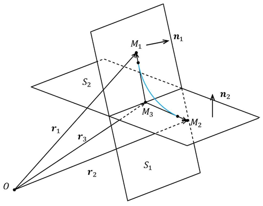
Consider the analytical method of smooth conjugation of planes using the example of conjugation of two intersecting planes arbitrarily oriented in space, which allows us to obtain the conjugation surface in an analytical form with a given order of smoothness.
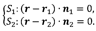
At the first stage of solving the problem, we introduce into consideration two planes S1 and S2, which are set by their normal unit vectors and radius vectors r1, r2 of fixed points (Fig.2.1).
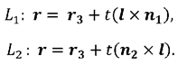
An analytical record of the line of intersection of planes can be represented by a system of vector equations
(fig 2.1)
The first step in the procedure for solving the problem is to obtain the line of intersection of the planes in a parametric form
The equation of the line of intersection of the planes L is searched for in the following parametric form
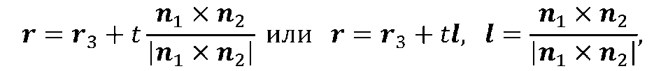
(Figure 2.2) where r3 is the radius vector of a point on the line L, l is the unit vector of this line.
At the next step, the position of such a point M3 is found, which lies at the intersection of the straight line L with the straight line perpendicular to it, lying in the plane St and passing through the point Mg. The position of this point can be found by solving the following system of equations
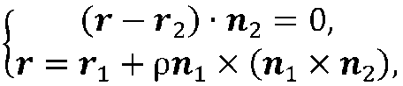
(Figure 2.3) where p is a system parameter.
The first equation defines the plane S2, and the second equation defines a straight line in parametric form passing through the point M1; lying in the plane S1 and perpendicular to L.
Let's substitute the radius vector of the point М3 into the system (2.3). Eliminating the vector r3 from this system, we find the value of the parameter p
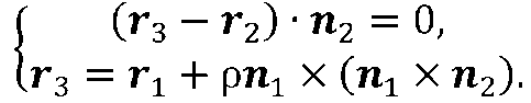
Excluding the vector r3 from this system, we find the value of the parameter p
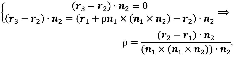
Substituting the found value of the parameter p into the second equality of system (2.3), we find the position of the point M3
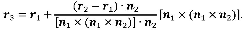
(Figure 2.4)
Using Identity

Which follows from the rule for calculating the double vector product, formula (2.4) is converted to the form
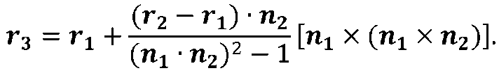
Substitution of the obtained value r3 into formula (2.2) gives the equation of the line of intersection of planes St and S2 in invariant parametric form
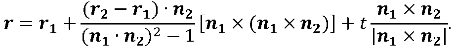
(fig 2.5)
In this case, the denominator turns to zero when the planes are parallel.
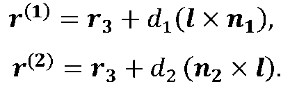
Further solution of the problem of smooth conjugation of planes is to find the rays L1 and L2. Rays Lt and L2 originate from point М3, lie in planes S1 and S2 and are perpendicular to line L.
Further on the rays Lt and L2 points are selected at distances dt and d2 from the line of intersection of the planes. In this case, their position is determined by the equalities
Smooth conjugation of rays Lt and L2 is carried out using a vector polynomial of the fifth degree

(fig 2.6)
The degree of the polynomial is selected from the conditions for ensuring smooth conjugation of rays L1 and L2, under which the following boundary conditions are satisfied:
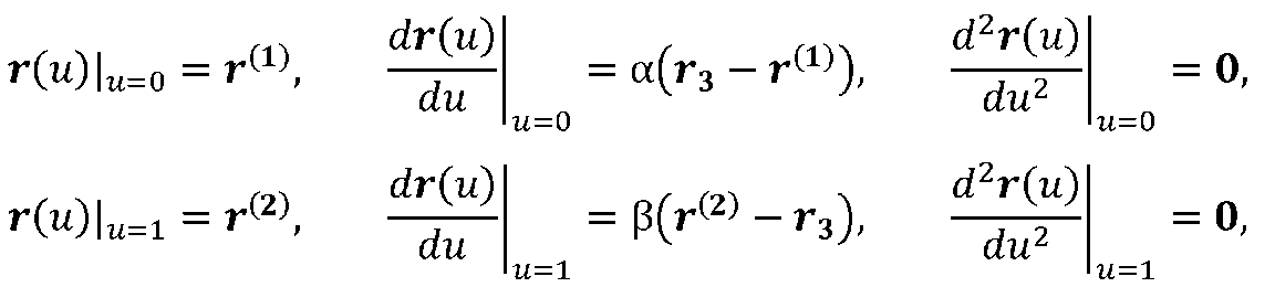
Substitution of the vector polynomial (2.6) into the boundary conditions leads to the following system of linear equations with vector unknowns
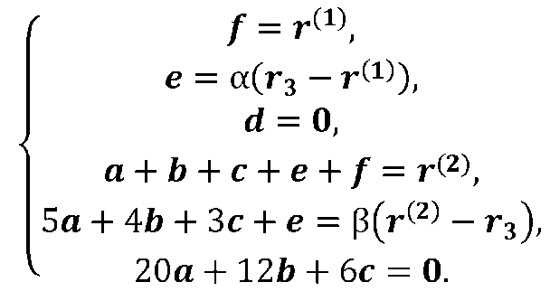
This system is reduced to a matrix equation for three unknown vectors a, b, c.
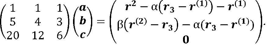
The solution to this system in invariant form is written by the equality
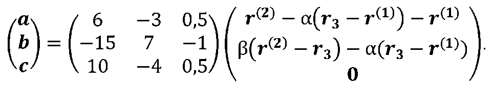
Where from
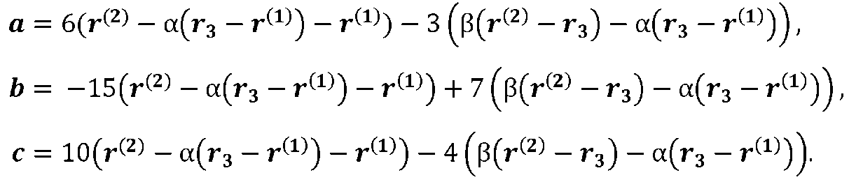
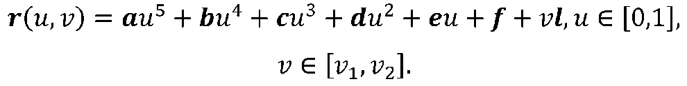
Finally, the surface realizing the smooth conjugation of the planes S1 and S2 is found as a transfer surface with a generatrix in the form of a polynomial of the fifth degree (2.6) and a direction vector l.
(fig 2.7)
As an example, we consider the conjugation, made in the computer algebra system Mathcad, of two planes (Fig.2.2).
with parameter values
By the equation of the generating curve

the curvature is determined on the conjugation interval by the formula
Baseline for the fillet of two planes
2.2 Method of smooth conjugation of curves and planes
Rotation or rotation of the three–dimensional Euclidean space together with the parallel translation form the so–called subgroup of motion of the group of affine transformations. Mathematical algorithms for transforming rotation are in demand when solving various problems of rigid body dynamics, robotics, animation, and solid modeling. Various algorithms are used to solve problems. Thus, rotation around an axis arbitrarily oriented in space is traditionally solved by sequentially performing operations of parallel translation and rotation around coordinate axes.
Consider a generalized method of rotation around an axis with a unit direction vector I passing through a given point in the space Mg. With this transformation, all points of the axis remain stationary, and the remaining points rotate in planes perpendicular to this axis by the same angle d.
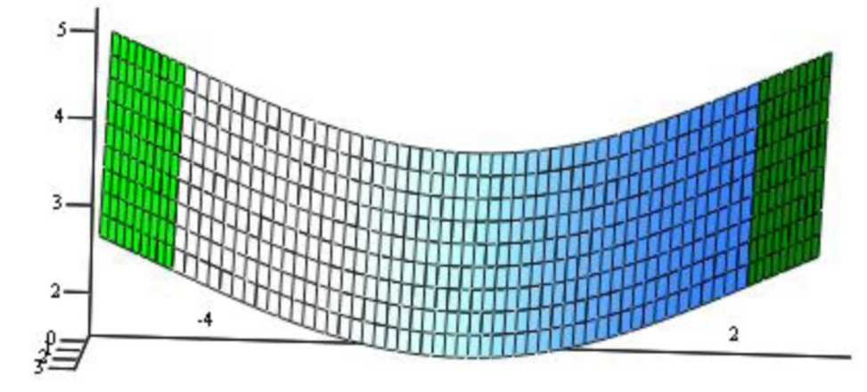
Surface of smooth fillet of two planes
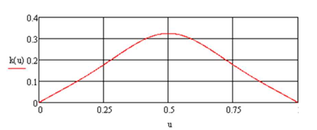
The graph of the change in the curvature of the curvature of the curved surface of a smooth conjugation, built in the computer algebra system Mathcad
Considering equality

we have
or

For geometric reasons, we find that
At the same time

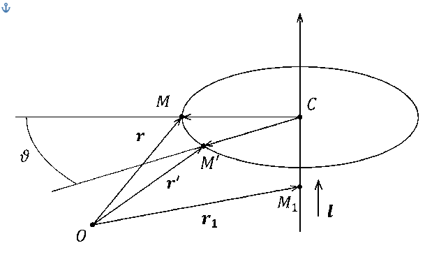
Scheme of rotation of a point M in Euclidean space around an arbitrary axis, with a unit direction vector I passing through point Mg
As follows from the graph of changes in the curvature of the generating curve (Fig. 2.3), at the given values of the correcting parameters of the air, the change in the curvature of the generating curve occurs symmetrically. By varying these parameters, the change in curvature can be implemented according to different laws, taking into account the required modeling goals.
Conclusion
According to the results of the analysis of existing methods of geometric modeling, it was found that in the mathematical modeling of complex geometric objects and their transformations, two main approaches are used – numerical methods in CAD problems, computer graphics and analytical geometric modeling. By means of CAD, the designed object is numerically constructed from geometric bodies, called graphic primitives, which can be transformed by one or another software means. The accuracy of the geometric object model is ensured by the accuracy of the point–to–point transformation of the base primitive. Analytical methods have a high degree of accuracy of modeling results, since each point of a geometric object is set analytically and transformations are performed synchronously.
There are algorithms for smooth conjugation of curves and planes in the development of a system for geometric modeling of mechanical engineering parts using CAD methods based on the use of numerical methods. The degree of smoothness of the conjugation depends on the number of control points, which increases the algebraic degree of the conjugation curves and complicates numerical calculations.
The operation of rounding edges is carried out using computer geometry methods, which are based on conjugation in analytical form using surfaces of constant radius
The main application of methods for creating perspective images is solving computer visualization problems. The theoretical foundations of the corresponding methods are laid in projective geometry. The main tools for modeling the construction of a central projection are projective matrices in homogeneous coordinates using global and local coordinate systems. The projection object is specified by a pointwise numeric array of its coordinates. The location of the projection plane is strictly frontal.
Along with those considered, a different approach to mathematical modeling of the transformations presented above is possible, when the modeling objects are specified in analytical form, and all transformations are performed in analytical form, regardless of the choice of the coordinate system.
A review of the existing methods for describing the rotation of a rigid body, as the most widely used transformation, indicates a wide variety of approaches to solving the problem. The unifying is the use in different forms of representation of the rotation matrix around the axis passing through the origin. Rotation around an axis passing through an arbitrary point in space is performed by composition of rotation transformation about coordinate axes and translation transformation. In this case, a prerequisite is the introduction of a moving and stationary frame of reference.
An effective means of describing the spherical motion of a rigid body is the use of quaternionic parameterization, which in recent years has been increasingly used in problems of motion control, robotics and computer animation. In this case, the method of spherical linear interpolation of quaternions is gaining popularity. There are no methods of nonlinear interpolation of quaternions that allow setting the kinematic laws of spherical motion in a wider range in the scientific literature. It seems expedient to obtain algorithms for describing the rotation of a rigid body with respect to an axis of an arbitrary position, independent of the choice of the coordinate system and convenient for implementation in computer algebra packages.
The result of the review allows us to conclude that it is advisable to create universal mathematical methods for the analytical description of complex geometric objects and their transformations, which are based on the fulfillment of the requirements for independence from the choice of the coordinate system and compatibility with existing analytical representations of objects
These are the methods that will make it possible to carry out computer modeling of transformations of complex geometric objects in computer algebra packages.
List of sources
- Kazanovich Y.B. Image segmentation using dynamic neural networks / Ya.B. Casanovic. // Scientific session of MEPhI – 2008. X All–Russian Scientific and Technical Conference
Neuroinformatics–2008
: Lectures on Neuroinformatics – Part 2. – M .: MEPhI, 2008. – P. 37–97. - Zapryagaev, S.A. Zapryagaev S.A., Zapryagaev A.I. Software shell for searching primitives in the image. Sorokin. // Bulletin of Voronezh State University, Series System Analysis and Information Technologies – No. 2 – 2008. – P. 37–47.
- Introduction to contour analysis: applications to image and signal processing / Ed. Ya.A. Furman. – M .: FizmatLit, 2003 .–– 592 p.
- Vinogradov, A.N. Selection and recognition of local objects in aerospace images / [Vinogradov A.N. and etc.]. // Aerospace Instrumentation – No. 9 – 2007. – P.39–45.
- Khaikin, S. Neural networks: a complete course / S. Khaikin., [trans. from English]. – 2nd ed. – M .: Williams, 2006 .–– 1104 p.
- Ermolenko, A.V. Application of Fourier transform for transforming objects in neural network analysis of images / A.V. Ermolenko. // Proceedings of the conference
Integrated models and soft computing in artificial intelligence
– M .: Publishing house of MSTU im. N.E. Bauman, 2009. – S. 39–75. - Bocharov, D.M. Methods for converting 2D photographs of a room into a 3D model / D.M. Bocharov, R.A. Sorokin // Current information systems and technologies: materials of other international scientific–practical conferences (Sumi, 21–24 May 2013) / Sumy State University. – Sumi, – 2013 .–– S. 150–151.
- Bocharov, D.M. Preliminary processing of 2D images during 3D reconstruction / D.M. Bocharov, R.A. Sorokin // Artificial Intelligence. Intelligent systems AI–2013: materials of the international scientific and technical conference (Katsiveli, Crimea, September 23 – 27, 2013) / Donetsk National Technical University. Donetsk, – 2013. – P.70–72.
- Bocharov, D.M. Filtration and segmentation of images for 3D reconstruction tasks / D.M. Bocharov, R.A. Sorokin // Information control systems and computer monitoring: materials of the V international scientific and technical conference of students, graduate students and young scientists (Donetsk, April 22 – 23, 2014) / Donetsk National Technical University. – Donetsk, – 2014 .–– S. 398–404.
- Kudryashov, A.P. Reconstruction of three–dimensional scenes of urban environment / A.P. Kudryashov // Information Technologies. – No. 7. – 2009. – S. 63–68.
- Sorokin, R.A. Selection of geometric figures in the photograph / R.A. Sorokin, D.M. Bocharov // Innovative perspectives of Donbass: materials of the international scientific and practical conference (Donetsk, May 20–22, 2015) / Donetsk National Technical University. – Donetsk, – 2015 .–– S. 86–90.