Back to library
Extrusion is a field which has naturally generated it's own terminology and this is an attempt to put together a small selection of the words used and what they mean.
The components of the extrusion line are relatively similar whatever type of extruder is used and a typical layout is shown diagrammatically below. The line consists of the basic extruder (drive, gearbox and screws), the extrusion die, the calibration units, the haul-off, the saw (or other cutting device) and finally the treatment devices for final finishing and handling. Major advances have taken place in all components of the extrusion line in the past decade but perhaps the most important have been in the output rates possible and in the command and control segments of the extruder. The advances in output rates have been driven by the demands of processors and the improved control systems have resulted from the availability of low cost computer processing power.

• The extruder drive is electrical in operation and is geared via a thrust bearing to produce the rotational movement of the extruder screw.
• The polymer feed to the screw is from the feed hopper and the feed may be by gravity, metering screw or simple conveying spiral.
• The extruder barrel and screw are of high strength steels and are protected from wear and corrosion by a variety of hardening and coating treatments such as nitriding and hard chroming.
• The barrel and screw are zoned into between 3 and 7 sections which are individually heated and cooled depending on the material and process parameters. The multiple functions of the extruder screw are given in more detail below.
• The die channels the polymer melt from the front of the screw to form the basic shape of the desired product.
• The calibration units stabilise the form of the output to the detailed shape whilst the polymer is being cooled.
• The haul-off provides the dragging force to overcome the frictional forces in the calibrators and to pull the profile through the calibrators.
• The saw / cutter cuts the profile to the desired length.
• Additional operations may be performed in the line or at the end of the line depending on the operation.
The extruder screw has the following basic functions:
• To bring the feedstock into the extruder and to move the material along the screw whilst at the same time compressing it and removing volatiles.
• To soften the melt by heating it (both from internally generated shear forces and externally applied heat).
• To mix the melt and produce a homogeneous melt without impurities.
• To apply the constant pressure (free of pulsation) required to force the material through the die.
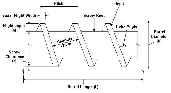
These functions, at least for the single screw extruder, are generally achieved at different sections of the extrusion screw as the material progresses along the barrel and the functions are illustrated below.

In absolute terms probably the most referenced number for extruder specification is the L/D ratio (barrel length/barrel diameter) as this defines many of the operating characteristics of the extruder for all types of extruders The L/D ratio is a major factor in the effectiveness of the extruder and of the types of material that it can process. For most extruder types the L/D ratio has increased as technology has advanced. The limitation to high L/D ratios is the torque available from the motor (longer screws mean higher friction) and the capacity of the thrust bearings of the extruder. As advances have been made in these areas then the L/D ratios have steadily increased from L/D's of around 15 to up to 30 in 1998.

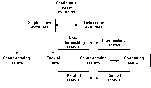
Basic extruder types There are many different types of extruders and the illustration below attempts to divide these into a logical order.

The two main types - co-rotating and contra or counter rotating screw machines have different screw rotations in the barrels and these are shown below:

Adiabatic Extrusion
A method of
extrusion in which the sole source of heat is the conversion of the drive energy
through the viscous resistance of the plastics mass in the extruder.
Barrel
The
portion of the extruder surrounding the screw or plunger. Barrel Liner A sleeve
forming the internal surface of the barrel.
Compound
Plastics material as
prepared for a further manufacturing operation particularly for extrusion,
moulding or calendering.
Compression section
Part of the transition section in
which there is a reduction in screw channel volume.
Cooling tank
A tank commonly
containing water through which extrusion is continuously passed for cooling.
Back to library