Abstract - A mathematical model of the reliability of an overcurrent protection system is proposed. The model lakes account
of the frequency of failure in the protection system, its monitoring time and the frequency of short circuits at the plant protected in the
active zone of the system. Examples of calculation are given.
Key words: Electrical network, mine, overcurrent protection, reliability, mathematical model.
When assesing the reliability of a relay protection system, two kinds of failure must be distinguished: failure to act in the presence of a
corresponding signal at the input of the system (failure to act) and action in the absence of a signal (false or excessive actions) [1, 2].
The effect on reliability in terms of selectivity and failure characteristics for mains overcurrent protection systems arc different. False
and excessive actions usually lead to loss of supply to consumers in the service area and, in most cases, to moderate material losses.
The protection system failure to operate may result in so-called burning-out short circuits (SC), during which combustible materials
surrounding underground power cables (coal dust, wooden reinforcement etc.) arc usually ignited [3].
An overcurrent protection system failure may be the result of the coincidence in lime of two random events: a fault in the plant being
protected (a short circuit in the power cable network or equipment protected, in which case protective action is mandatory) and a
failure in the protection circuit [4].
Let us denote a random time interval between consecutive failures of an overcurrent
protection system asξi(0) .A random time interval during which the protection is in an
unrevcaled fault state will be denoted as ξ i(1), i=1,2,…,n .
The time interval depends basically on the frequency of inspections and the qualifications of the maintenance personnel.
Let us denote a random time interval between consecutive short-circuit faults in the protection system action zone as
η j(0) and the time of the short-circuit fault (or time of protective action) as a random variable
η j(1) j=1,2,…,m.
When the independent time intervals
ξ i(1) and η j(1) occasionally coincide, a protection system
failure or a buming-out short-circuit fault or a burning-out short circuit in the network occurs each time the protection circuit is in
a failure slate (a fault in the protection circuits, faulty setting of the protection or the protection system is switched off), and at this
time a short-circuit fault occurs in the action zone of the protection system considered.
The problem is to determine the mean time Ò to the first protection system failure or to the first burning-out short-circuit fault, the
dispersion of the time interval σ2 and the probability of failure-free operation R (t).
To solve the problem, let us make some assumptions. The protective devices can only fail when in a waiting state. If a protection
system has been in a healthy state at the moment of a short-circuit fault, it is unlikely to fail when in an alert state
[4 – 6]. After each failure
the protective device fully recovers (in mains electrical equipment the protection units are usually detachable). Failures in the protection
circuits are only revealed and removed in the course of maintenance inspections.
The change in the protection circuit state with time can be represented as a random function ξ(t),
with two values: "0" and "1". State "0" means that mere are no failures in the protection circuit, and state "1" stands for the presence
of failures in the protection system. Sequential random time intervals ξ 0(0),
ξ1(0),…, ξi(0) ,…,
ξn(0) represent the working state of the circuit, and ξ
0(1), ξ1(1),…, ξi(1),…, ξn(1)
the non-operating state.
Let all the ξi(0) be characterized by the same distribution

and all the ξi(1) have the distribution

Variable λ0 is the failure rate of the protection circuit, and
μ0 is the recovery rate. Variables ξi(0) and ηi(1)are mutually independent..
The state of the plant being protected is described by a similar random function η(t),
that can assume two stales: state "0"
showing that there are no failures in the protected plant leading to a short-circuit fault, and state "1" showing that a short-circuit fault has
occurred. The sequentially alternating random time intervals between faults will be denoted by
η 0(0), η 1(0),…, η j(0),…, ηn
(0) and the durationof the short-circuit fault (the time of protective action) by η 0
(1), η 1(1),…, η j(1),…, ηn(1) èìåþò ðàñïðåäåëåíèå

and all the η j(1) have the distribution

Variable λ1 is the frequency of short-circuit faults in the protected plant, and μ1is the frequency of tripping of the faulty plant by the protection system. The variables
η j(0) and η j(1) are also independent.
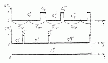
A risk of protection system failure arises when the processes ξ(t) and η(t)
overlap in their "1" states, i.e. when, owing to failures in its circuit, the protection system cannot trip a faulty network element (see Fig. 1).

FIG. 1.
We shall assume that initially ξ(0)=η(0) = 0, i.e. there are no failures in the protection circuit and there are no faults in the
plant being protected. After protection system failure has occurred, the situation is repeated, the time interval
T2(0) between the first and second failure of a protection system being a random variable independent of
T1(0),but having the same statistical distribution and, in particular, the same mean value
Ò ,etc.
We shall consider the pair of processes [ξ(t), η(t)] as a semi-Markov process (SMP) [7] with four states:
e1 (0,0)
–
no failures in the protection system circuit and no short-circuit faults m the protected plant; å2 (0,1)
–
no failures in the protection system circuit and a fault in the protected plant; å3 (1,0)
a failure in the protection system circuit and no faults in the protected plant;
å4 (1,1)
–
a failure in the protection system circuit and a fault in the protected plant.
Let us subdivide the set of protection states Å into two subsets so that E+∪E
- , Å+∩Å-=Ø, where E+{e1, e2 ,
e3} is the set of safe protection states, and E- {å4}
is a faulty protection state.
The time of the protection system being in state å1 (0,0) is determined by the shortest time interval of
ξi(0),ηj(0)
i.e. ζ1=min{ξi(0),ηj(0) }
the time of the protection system being in state å2 (0,1) is determined by the shortest time interval of
ξi(0) and ηj(1),
i.e. ζ2=min{ξi(0),ηj(1)},
and the time of the protection system being in state å3 (1,0) is determined as
ζ3 =min{ξi(1),ηj(0) }.
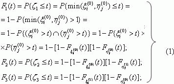
The probability distribution functions of the time of a protection system being in each of the ei=1,2,3 states are determined as follows:

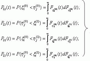
The probability of the system transferring from slate å1 to state åj
in a time not exceeding t can be determined as follows [8]:

The probability of the protection system operating safely in the time interval [0, t] R(t), ), will be defined as the probability of a semi-Markov process to be in subset
Å+ for the time t , provided that at the instant
t = 0 the process is in state e1.
To estimate Ihe probability R(t) a Laplace-Stieltjes transform Ψ(s), is first calculated, followed by a
Laplace transform of the required trouble-free operation probability [9]

For calculating Ψ (s) we shall use a general set of equations initially developed in [10].
In our case the set of equations becomes

where Fi(s) and Pij(s) ) are Laplace-Stieltjes transforms of the probability distribution function of the
semi-Markov process being in state å1
and of the transfer probabilities Pij(t) :

Solving the set of equations (4) with respect to Ψ(s), we obtain

Substituting distribution functions of random variables ξi(0),ξj(0)
and ηi(1),ηj(1) in (1) and (2) and making allowance
for (5), we obtain the expression

After substituting Ψ (s) from (7) in (3), we obtain

where

To obtain an inverse Laplace transform we shall apply the following formula from [11]:

where sk are the roots of the equation Z'(s) = 0.
For our case, Z' (s) takes the form


With the substitution s=y-a/3 the cubic equation is brought to an incomplete form [12]:

where

For the problem in question Q<0 è ð<0, , and then the roots of cubic equation (10) will be determined as follows:

Substituting tlie values of roots s1, s2 and s3in (9), we obtain

The mean time to the first failure of a protection system Ò and its dispersion σ2 ýcan be
determined using known relationships [9]

Using formula (7), we find that

where

Denoting the mean time of the protection system as d0=1/λ0
the time for the protection system to be in a faulty state asd0=1/μ0 the mean
time interval between consecutive short-circuit faults in a protected network asd1=1/λ1,
and the mean time of the short-circuit fault in the operating zone of the overcurrent protection system in question as d1 =1/μ0 - ñðåäíåå âðåìÿ ñóùåñòâîâàíèÿ
formula (15) can be represented in the form

Taking into account that, for overcurrent protection systems, the relationships
d1<< d1, d1<<
d0 and d0<< d1, valid, fonnula (17) can be simplified to

With the same conditions, fonnula (16) will take the form

The probability of trouble-free operation of the protection system R(t), derived using formulae
(8)
–
(13),can be replaced,
with adequate accuracy for practical calculations, with an exponential function, subject to the condition T/σ≈1

The mean time for tlie protection system to be in an unrevealed faulty stale can be determined as follows [13]:

where τinsp is the time interval between inspections of the protection
apparatus, as specified by regulation documents in force.
For the case when τinsp/d0<0,1, formula (21) takes the form

Substituting (22) in (18), we obtain

Example 1.
The problem is to determine the probability of trouble-free operation of an overcurrent protection system for the time t = 8760 h in a PVIR-63
starter energizing a remote, small gearmotor. The sensitivity of the overcurrent protection inserted in a common AV-320 aiilomatic switch is insufficient to
provide downstream backup of the starter overcurrent protection for occasional short-circuit faults on a cable line running from the starter.
A leakage relay at a TSShVP 400/6-0.69 transformer substation is inoperable.
Èñõîäíûå äàííûå:
ñthe mean time interval d0 between successive failures of the overcurrent protection
system (the failures are revealed in the course of maintenance inspections) is 4000 h;
èíòåðâàë âðåìåíè ìåæäó; the time interval &tauinsp 2160 h;between successive inspections of the overcurrent protection system is
the mean time interval d1: the mean time interval 700h.
Using formula (21), î, we calculate the mean time for which the protection system is in an unrevealed faulty state:

Using formula (18), we find the mean time of trouble-free operation of the overcurrent protection system:

We shall determine σ using formula (19):

The trouble-frce operation probability function R (t) will be determined by formula (20), since the condition
T/σ≈1is fulfilled:

Example 2.
The problem is to determine, using the source data of Example 1, how much the reliability of the
ovcrcurrenl protection system would be increased if its inspection interval τwere 720 h.
Using formula (21), ), we find that
d0 = 80 ÷. Applying formula (18), we establish thai
T1 = 39700 ÷. Then, using formula (20), we find that R1 (8760)=0,8
Hence, wilh a threefold reduction in the maintenance intervals of the protection system, the mean time interval for trouble-free operation
of Ihe proleclion system increases by a factor of 3.77, while the probability of protection system failure for the time interval t = 8760 h increases by
a factor of 2.8.
CONCLUSIONS
The proposed reliability model for proleclion systems used in underground power networks
in coal mines differs from the known models in accounting for the mean lime of a protection system being in an unrevealed faulty
state and for the frequency of ils maintenance inspections.
REFERENCES
1. RIPS Ya. A., Calculation of relay protection operating reliability, Elektrichestvo, No. 4, 1968.
2.Reliability of Power Engineering Systems. Terminology. Ë Collection of Recommended Terms,
Nauka, Moscow, 1980.
3. KOVALENKO M. I., ZRELYI V. Ò., KHOROL'SKII N. F. el al.. Prevention of Fires and Explosions in Coal Mini's, Nedra, Moscow, 1983.
4. FABRIKANT V. P., The application of reliability theory to relay protection device assessment, Elektrichestvo, No. 9, 1965.
5. SMIRNOV E. P., Tile effect of maintenance testing on overall relay protection reliability, Elektrichestvo. No. 4, 1965.
6. BARZAM À. Â., A response to E. P. Smimov's paper, Elektrichestvo, No. 8, 1967.
7. KOROLYUK V. S. and TURBIN A. F., Semi-Markov Processes and their Applications, Naukova Dumka. Kiev, 1976.
8. BRODI S. M., VLASENKO O. I. and MARCHENKO B. G., Calculation and Planning of Reliability Testing of Systems, Nnvkova Dumka, Kiev. 1970.
9. KREDENTSER B. P., Reliability Prediction for Systems with Time Redundancy, Naukova Dumka, Kiev, 1978.
10. KOROLYUK V. S., Time for a semi Mnikov process to be in a fixed set of states, UMZh, No. 3. 1965.
11. MARTYNENKO V. S., Operation Calculation, Vysshaya Shkola, Kiev, 1973..
12. BRONSHTEIN I. N. and SEMENDYAYEV K. A., Reference Book on Mathematics for Engineers and Students of Higher Enginering Schools, Nauka, Moscow, 1986.
13. KOVALEV A. P., Problems of safety assessment of electrical engineering facilities, Elektrichestvo. No. 8, 1991
Authors:
ALEKSANDR PETROVICH KOVALEV graduated from the Electromechanics Department of the
Donetsk Polytechnic Institute (DPI) in 1972 and from the Mathematics Department of the Donetsk State University (DSU)
in 1977. In 1992 he received the degree of Doct. Techn. Sci. from the DPI. His thesis dealt with safety engineering and fire prevention.
He is an assistant professor at the DPI.
IGOR VLADIMIROVICH BELOUSENKO graduated from the Power Department of the DPI in 1981. In 1991
he received the degree of M. Techn. Sci. from the DPI. His thesis dealt with power systems and their control. He is the
Chief Production Engineer at the Gazprom Russian Joint Stock Company.
VALENTIN PAVLOVICH MUKHA graduated from the Electrical Engineering Department of the
DSU in 1975. He is an assistant at the DPI.
ANDREI VLADIMIROVICH SHEVCHENKO graduated from the Mathematics Department of the DSU in 1975.
He is an assistant at the DPI.
Back
Library


