Sealing a drilled shaft
By James Cobbs, PE, amd David Cobbs,
PE, Cobbs Engineering, Tulsa, Oklahoma
In the last issue of Mine to Drill we discussed drilled shaft lining systems. Here, we continue with a discussion of sealing those shaft linings.
Almost all drilled shafts have some sort of a lining installed which is fixed in the shaft. Fixing the lining in the shaft is usually done with a sealing material. The need to seal a shaft lining can vary from none to critical. Items to consider in determining sealing needs include: the cost of pumping water that enters the mine through a shaft; whether the mineral to be mined is soluble; and whether the shaft is to serve a high vapor pressure product storage cavern.
For water soluble minerals such as potash, salt or trona, effective sealing may be critical to the stability of the mine itself. In a storage cavern for a water reactive product, such as anhydrous ammonia, sealing is critical to the operation of the facility.
A number of techniques are avail-able for sealing shafts depending on the particular needs of the facility. Most of the sealing techniques are relatively simple, but careful consideration in the selection of techniques and planning the operation are required for the best and most economical system. Attention to details in the execution of the sealing operation is of equal importance.
Sealing materials
The most common sealing material in drilled shafts is neat Portland cement grout. There have been a few shafts where a combination of Portland cement and a bitumen for sealing, along with a sanded grout were used. Though it is not in the strictest sense of the word sealing, there have been shafts in which cement grout was used for a seal across water bearing portions of the shaft and the balance of the shaft was backfilled with sand or pea gravel for annular fill.
For economy and other reasons, cement slurries can be extended with bentonite, expanded perlite, diatomaceous earth, pozzolan or sand. Extending the slurry with additives that decrease the Placement methods formations penetrated are weak and may not support the pressure of a full column of neat cement slurry.
For especially important operations, Portland cement can be modified by additives to create a grout which will expand upon setting. Cement can also be modified to make it thixotropic as well as expanding. This is valuable when there is the possibility of grout loss into fractured formations.
In cases of special needs, the lining of a shaft can be grouted in part with a polymeric material, which will imbibe water and expand into a water channel or channels to perfect the seal. This material is also elastic, which can be a valuable feature when the shaft lining is to be exposed to large temperature changes.
Placement methods
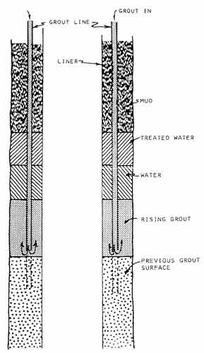
Almost all drilled shafts are grouted with tremies, usually called grout lines, in the lining-borehole annulus as shown in Figure 1. Multiple grout lines are important in achieving uniform placement of grout around the lining. There have been shafts with only a single grout line, but several of them suffered poor sealing and required remedial work to perfect the seal. The usual practice for smaller shafts is to use four grout lines, equally spaced around the shaft. For larger shafts it is common to use six or eight equally spaced grout lines in the annulus.
Figure 1. Grouting a shaft.
For small diameter shafts with good clearance in the annulus, the grout lines can be run in the hole without guidance. able feature when the shaft lining is to be Where clearance is reduced, and for deep shafts, the best practice is to install guides on the outside of the lining, to assure that the grout lines are properly placed in the annulus. The guides should be essentially continuous from the top to the bottom of the lining. Normally, the guides are standard pipe of sufficient at diameter to accept the grou lines. The guides are perforated to allow grout to flow out of the guides without restriction.
Because of the volumes involved and the pressure of wet grout, the sealing operation usually divided into stages. Sutficient time is needed between stages to allow for an initial set before placing the next stage.
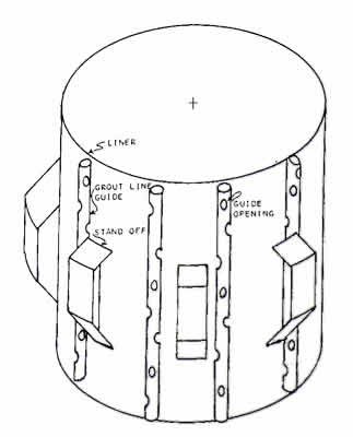
Since the lining will almost always hang eccentric within the borehole, steps should be taken to assure a minimum stand-off of the lining from the borehole wall. Centralizers or stand-off devices do not need to assure perfect centralization of the lining in the hole, but rather are needed to maintain a minimum space between the lining and the borehole wall. Most commonly, the stand-off devices are structural T sections attached axially to the outside of the lining. Grout line guides and centralizers are illustrated in Figure 2.
Figure 2. Stand-off devices (centralizers) and grout line guides.
Most drilling muds are adversely affected by excessive calcium ion which is plentiful in Portland cement liquor. The excess calcium can flocculate the drilling mud, creating a gelatinous mass through which grout will channel or finger, leaving portions of the annulus filled with mud. Subsequently, the mud can be leached out, creating pathways for water or escape of stored product from shafts serving storage caverns.
The complete replacement of drilling mud by water has been used to assure good grout placement. This is usually not necessary and in some cases is harmful. The more common practice is to pump a quantity of water through the grout lines to establish a buffer zone between the ascending grout and the drilling mud in the hole. An improvement on this practice is to pump a quantity of water with a mud thinner, followed by plain water, prior to pumping the grout into the shaft. This is also illustrated in Figure 1.
Unique sealing operations
In 1968, a mined storage cavern for anhydrous ammonia was constructed beneath a drilled shaft in the flood plain of the Delaware River in New Jersey. Anhydrous ammonia is soluble in water and the solution process is exothermic. With the solution of ammonia in water, there is a temperature and an attendant rise in pressure. Because of these factors, effective sealing of the shaft and auxiliary holes to serve the cavern was critical. To further complicate the design problem, the ammonia was to be delivered to the cavern at atmospheric pressure and -28 degrees F. After pumping into the cavern, the ammonia was to come to thermal equilibrium with the surrounding rock. The cooling of the steel linings was certain to cause the linings to shrink away from encasing grout, which would provide a channel for water leakage into-or ammonia leakage out of the cavern.
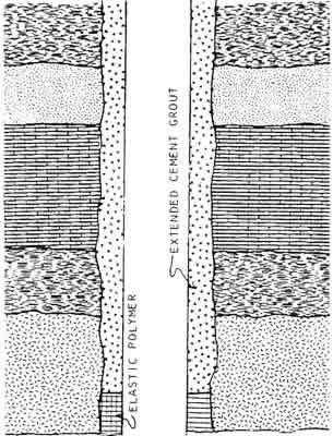
To solve these problems a unique sealing system was designed. All but the bottom 25 feet of the steel linings were coated with an enamel to assure that the steel and grout would not bond. When the linings were grouted in the holes, the bottom 25 feet of the linings were grouted with the polymeric material previously described. This material exhibits good elasticity at low temperature and it was to provide the seal in the shaft. The balance of the shaft annulus was filled with an extended Portland cement grout. This design is illustrated in Figure 3.
Figure 3. Sealing of a cryogenic storage shaft.
Over an extended period of withdrawal and placement of ammonia in the cavern, the cavern temperature had reached a stable 0 degrees F and a gradient in the surrounding rock reached ambient ground temperature in about 25 or 50 feet. The cavern has been in continuous operation since construction, with no loss of product or entry of water into the cavern.
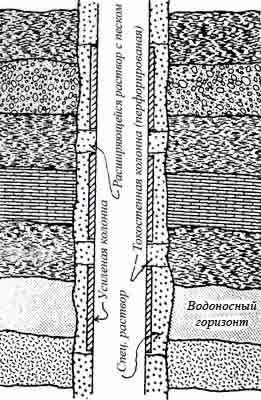
Another unique sealing operation was practiced by Kerr McGee in its uranium mines in New Mexico. In this area there are two or three prolific aquifers and the balance of the rock is dry. In these operations a liner capable of resisting the hydrostatic head was placed opposite the aquifers, with only thin steel shells opposite the dry zones. The aquifer zones were sealed with a premium Portland cement system and the dry zone annulus portions filled with an extended cement grout or sand. To prevent the buildup of water behind the weak lining sections, they were perforated to permit the drainage of any accumulated water into the shaft. This procedure assured that an effective, though not necessarily perfect, seal was achieved in the shafts. This system is illustrated in Figure 4.
Figure 4. Selective sealing of a shaft.