|
Vracheva Anna Aleksandrovna
Faculty:
Mining and Geological Faculty
e-mail: anna.vracheva@gmail.com
|
||||||||||||||||
|
The author's abstract master's works Subject: “Analysis of the Methods and Geodesic Technologies of
the Ground Laser Scanning”
|
|||||||||||||||||
|
ENG |
|||||||||||||||||
|
Introduction
Method of the laser scanning allows to create a digital model of the ambient space presenting it with the set of points with space (spatial) coordinates. Schematically any scanner can be divided into several basic components (parts, blocks):
Figure 1 – The principal of the laser scanner operation
There are two methods of determining distances. The first one is called Time-of-Flight (TOF). It is based on the measuring of the laser impulse action time. This impulse is generated by the sensor, reflected by the object and received by the sensing element.
n – environment refraction factor;  - impulse action time. - impulse action time.The second method is based on the phase difference measuring. The sensor radiates the harmonic vibrations of the set wave length, at this moment the initial phase becomes determined, then the signal is reflected by the object and received by the sensing element, at this moment the final phase is determined. The distance is calculated under the formula:
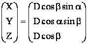
where N- number of the whole vibrations periods;  – wave length; – wave length; – final and initial measuring phases correspondingly. – final and initial measuring phases correspondingly. By the angle of the mirrors turn at the observation period as well as by the distance measured the processor calculates each point coordinates under the formula:
where X, Y, Z – point coordinates; D – distance measured;  – horizontal and vertical angles correspondingly. – horizontal and vertical angles correspondingly.Urgency and the purpose
In the most cases in the result of the laser scanning the object data are presented in the view of the rectangular Cartesian coordinates, whose system forms the so-called “cloud” of points. The review of conditions of researches and workings out on the theme
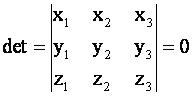
There are different algorithms of the planes determination. In particular, Andreas Rietdorf in his paper “Automatisierte Auswertung und Kalibrierung von scannenden Messsystemen mit tachzmetrischem Messprinzip” (Munhen 2005) [1] as a criterion for the decision, if the points lie on the plane, fulfilled the determinant calculation. There are correspondingly analyzed two adjacent triangles that rather precisely determine the plane.
Let us examine another algorithm.
Figure 2 - Transformation of the plane points coordinates, here:
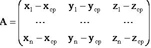
Let us deduct from each coordinate of the X matrix the average values (
By multiplying the A matrix by AT, we will receive a symmetric N matrix. This is required to define eigenvectors (U) of the A matrix.
where A’ – transformed matrix of points coordinates; A – parent matrix; U – matrix of the coordinates transformation while transition to a new basis. If the eigenvalues of the A matrix are pairwise different, then eigenvectors are orthogonal and linearly independent and, consequently, they can be used as a basis. Then formula (6) is as follows:
where A’ – transformed matrix of points coordinates; A – parent matrix; U – matrix of the coordinates transformation while transition to a new basis, consisting of the proper vectors of the A matrix. Planned results
The result of this research will be the creation of the program in Delphi environment, allowing to sort out geometric primitives. The final conclusions concerning the research results are planned to be drawn by December, 2008. At the present moment it is possible to say that the above described algorithm with the use of the transformed coordinates analysis gives a greater reliability of the results received than a similar algorithm with the use of the determinate. List of Sources: 1 Andreas Rietdorf «Automatisierte Auswertung und Kalibrierung von scannenden Messsystemen mit tachzmetrischem Messprinzip» - M?nhen 20052. N.V. Efimov “Short Course in Analytical Geometry” –M., “Nauka”. 3. D.V. Beklemishev “Course in Analytical Geometry and Linear Algebra” – M.,“Phismatlit”. 4. D.K. Fadeev, V.N. Fadeeva “Computational Approaches of Linear Algebra” – M., “Nauka”. |
|||||||||||||||||
|
|
|||||||||||||||||


 – coordinates system – this is a system where the plane lies; x, у, z coordinates system – this is a system where the points lies in the xy plane.
 ) of each coordinates. We will receive an A matrix, all points of which will be spread towards the center of gravity: