Event-driven Direct Current Controller
The traditional current control scheme consisting of discrete time current controller and pulse-width modulator is replaced with new event-driven Direct Current Controller (DCC), which evaluates the transistor switching patterns of inverter directly from the phase current errors ia, ieb, iec and stator voltage sector Sect. The stator voltage sectors are determined as depicted in Fig.3.
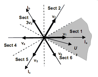
Figure 3 - Stator voltage Us sector allocation
Considering the situation in Fig. 3, the stator voltage Us space vector is in sector 1. In this sector voltage vectors v0, v7, v2 and v6 are selected for the current control. Vectors v0, v7 are two zero vectors, while v2, v6 are two nearest adjacent live output voltage vectors to the sector 1. Sequential switching among these vectors is determined by instantaneous current error vector ie sector, as allocated in Fig 4. According to the instantaneous current error vector ie sector, the voltage vector vi is selected which has the greatest influence on the elimination of the error, similar to Direct Torque Control (DTC) control approach.
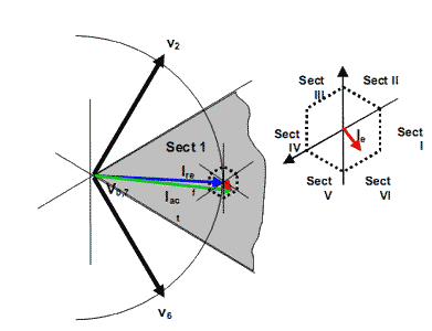
Figure 4 - Current error ie sector arrangement
Considering inherent on-off switching functionality of the inverter, the modulator can be designed as Discrete Event-driven System (DES). Four output voltage vectors v0, v7, v2 and v6 are considered as discrete states of the system. The events for the transition among discrete states are determined by combination of phase current errors iea, ieb and iec. Consequently, the current control functionality is integrated directly into the modulator. The structure of the proposed strategy for sector 1 is represented by Petri Net graph [1 1],[12](Fig. 5). Switching among zero and live vectors (transitions T1, T2, T4, T5, T6 and T8) is determined by signs of current errors iea and -iec. The switching among live vectors (transitions T3 and T7) is determined by the sign of current error ieb. Similar control strategy is applied for the remaining sectors.
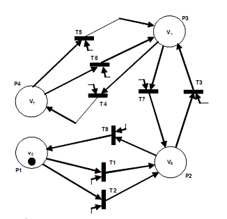
Figure 5 - PN-graph of EDCCM in Sector 1
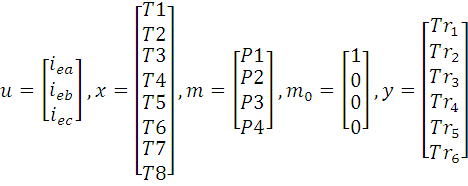
For the design, simulation and implementation purposes, PN-graphs are replaced by the matrix description of DES [16], which is schematically depicted in Fig. 6. Inputs, events, discrete states and outputs are denoted by logical variables u, x, m and y, respectively. m0 denotes initial discrete state.
|
|

Figure 6 - Matrix description of DES system
Simulations
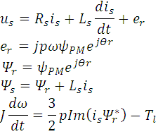
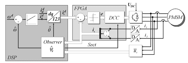
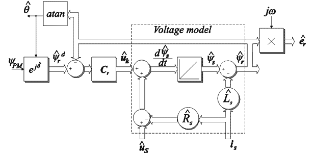
The proposed observer and controller performance was tested with both simulations and experimental system. Simulations were performed using MATLAB / Simulink on parameters of 0.8 kW PMSM AMG6308. Designed direct current controller modeled by proposed matrix-based approach was simulated using Matlab/Simulink. A Permanent Magnet Synchronous Machine (PMSM) was used as load connected to the three phase VSI. The scope of the simulation was to control the PMSM in the speed mode using the PI speed-controller and proposed direct current controller. The simulation scheme is illustrated in Fig. 7.
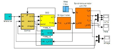
Figure 7 - The simulation scheme
Phase currents and voltages are measured, while the speed and position is calculated using rotor flux observer. The estimated drive speed is used for the speed control-loop, which is implemented by PI-controller and generates the q-component of the reference current in the d-q reference frame. The d-component of the reference current is set to 0. To comply with the designed current controller, the reference current is transformed from d-q to the a-b-c reference frame where it is denoted as id123. Actual load current is123 is measured directly from the phase lines using current transducers and fed back to the current controller. The current controller outputs are the signals for the control of transistors. Fig. 8 - 11 are showing the simulation results at low speed operation. The drive is started without load and accelerates to the reference speed. At the time 0.3 s the load is applied to the drive. Figure 8 shows the phase currents, where the current ripple can be noticed. Fig. 9 illustrates estimated rotor flux angle obtained from sliding mode rotor flux observer. The angle of the induced voltage calculated from voltage estimator differs from induced voltage angle during the load especially zero speed operation, therefore only information about induced voltage is not sufficient for sector determination as shown in Fig. 9. The speed observer successfully follows the real values while drive is reversed as shown in Fig. 10 even at speed reversing. Produced electrical torque is depicted in Fig. 11.
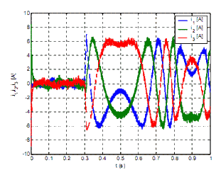
Figure 8 - Phase currents during the transient
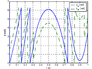
Figure 9 - Observed rotor angle and estimated angle of stator voltage
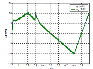
Figure 10 - Actual rotor speed w and observed rotor speed we during transition
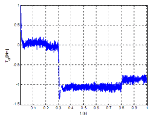
Figure 11 - Produced electrical torque
Experimental setup
Experimental setup, similar to [15], was configured to verify simulation results. It is implemented on DSP2 board [17], which includes the DSP TMS320C32 floating point DSP and Xilinx XCS40PQ240 FPGA. The speed control algorithm and sliding-mode rotor flux observer of the PMSM are implemented on the DSP processor coded in C language, where algorithm execution time was set to the switching period 166 ms. The cascade current control is designed using event-driven Direct Current Control implemented in FPGA. The algorithm is designed as DES and described using logical matrices. Both the DES matrices and algorithm from Fig. 6 are included directly in the VHDL code for FPGA.. FPGA also hosts the implementation of the interface for measurement of the phase voltages and two phase currents. The phase current error is calculated and converted into logical values for DES algorithm using comparators with hysteresis, which is also implemented in FPGA. A/D conversion is the most critical operation of the Direct Current Controller regarding time and takes 2.7 ös. According to the fact, that A/D conversion takes most of the calculation time, while the calculation of the current error, hysteresis comparators and DES algorithm takes less then 166 ns. The proposed approach replaces usual sequential calculation of algorithms on the DSP by parallel executable hardware.
Conclusion
Sensorless control of PMSM based on unique sliding - mode flux observer is presented in this paper. Sliding mode rotor flux observer based on PMSM model is used to obtain rotor position and speed. Rotor speed is estimated using observed angle of rotor. Initial rotor position is obtained by rotor position detection procedure. Operating range of sensorless control is extended using sliding-mode controller that extends the described features with robustness on parameter variation. Direct Current Control is used to integrate the functions of current controller and modulator. It is designed as event-driven system and represented using a novel matrix based description for such systems. Matrix description is used for implementation on FPGA, which allow higher switching frequency, comparing to the conventional PWM. The simulations confirmed potentials of the presented approach, although some optimization should be performed. Some potentials of suggested approach were already confirmed by experiments on FPGA devices for similar setup [15], where high switching frequencies (up to 200 kHz) were reported. This paper presents also the experimental setup for the sensorless torque and speed control of PMSM.
References
[1] J. Holtz, "Pulsewidth Modulation – A Survey," IEEE Transactions on Industrial Electronics, vol.39, No.5, December 1992, pp. 410-420
[2] K. Zhou, D. Wang, "Relationship Between Space-Vector Modulation and Three-Phase Carrier-Based PWM: A Comprehensive Analysis," IEEE Transactions on Industrial Electronics, vol.49, No.1, Februar 2002, pp. 410-420
[3] J. Holtz, "Methods of Speed Sensorless Control of AC drives", Sensorless Control of AC Motors, IEEE Press Book, (1996)
[4] V.I. Utkin, "Sliding mode control design and chattering problem", Electrotechnical Review, Ljubljana (SLO) 1993, vol.60, no.2-3, pp.75-81
[5] Z. Chen, "Sensorless Control of Interior Permanent Magnet Synchronous Motor by Estimation of an Extended Electromotive Force", IEEE Transaction on Industrial Electronics.
[6] T. Chin, M. Nakano, T. Hirayama, Accurate Measurement of Values of Voltage, Current and Power for Power Electronics Circuits, IEEE Transactions on Industry Applications, Tokyo, Japan, 1998.
[7] K. Jezernik, "Speed sensorless control of IM." V: PINDADO RICO, Rafael (ed.). Seminario anual de automática y electrónica industrial e instrumentación 2000, 13, 14 y 15 de septiembre de 2000. Barcelona: Universitat Politécnica de Catalunya, 2000, pp. XXIII-XXXII.
[8] L. Harnefors, H.-P. Nee "A general algorithm for speed and position estimation of ac motors" IEEE Trans. Ind. Electron., Feb. 2000, p. 77-83.
[9] H. Rasmussen, P. Vadstrup, H. Borsting “Adaptive observer for speed sensorless PM control”, IEEE IAS2003, Salt Lake City, Utah USA, October 2003
[10] Gregor Edelbaher, Evgen Urlep, Milan Curkovic, Valentin Kranjec, "Low speed performance improvement in sensorless drive using measured stator voltages of PWM voltage source inverter", V: Proceedings, International conference on industrial technology [also] IEEE ICIT 2003, Hotel Habakuk Maribor, Slovenia, December 10-12, 2003, Piscataway, IEEE, 2003, str. 542-547. [COBISS.SI-ID 8486166]
[11] Peterson J.L. “Petri Net Theory and the Modeling of Systems”, Prentice-Hall, New Jersey. 1981
[12] T. Murata. Petri nets: Properties, analysis and applications. Proceedings of the IEEE, 77(4):541--580, April 1989
[13] Rossi C., Tonielli A., “Robust Current Controller for Three-Phase Inverter Using Finite State Automaton”, IEEE Trans. On IE, Vol. 42, No. 2, pp. 169-178, 1998.
[14] Tilli A., Tonielli A., “Sequential design of Hysteresis Current Controller for Three-Phase Inverter”, IEEE Trans. On IE, Vol. 45, No. 5, pp. 771-781, 1998.
[15] Polic, A., Rodic M., Jezernik K., “Matrix based approach to overall functionality description of drives”. International power electronics and motion control conference, 2 - 4 September 2004, Riga, Latvia. EPE-PEMC 2004
[16] Polic, A., Jezernik K.,“Closed-Loop Matrix Based Model of Discrete Event Systems for Machine Logic Control Design”, IEEE Trans. on Industrial Informatics, vol. 1, Feb. 2005, pp. 39-46
[17] D. Hercog, M. Curkovic, G. Edelbaher and E.Urlep, “Programming of the DSP2 board with the Matlab/Simulink”, Proc. of IEEE ICIT 2003,
|


