Load as a Controllable Resource for Dynamic Security Enhancement
Information source: http://www.pserc.wisc.edu/ecow/get/publicatio/2006public/
ABSTRACT
The traditional form of load control (shedding) tends to be quite disruptive to consumers, and so is often avoided. The paper suggests an alternative strategy that is based on controlling individual loads, such that interruptions effectively go unnoticed by consumers. An hierarchical control structure is required, with lower-level substation-based controllers consoli- dating information about available controllable load. The higher- level controller uses that information to formulate strategies to steer the system through events. Model predictive control is proposed for the higher-level control.
Index Terms—Load control, voltage collapse, model predictive control.
1 INTRODUCTION
Dynamic security enhancement is often associated with improved performance of generator controls. Network controls, such as provided by FACTS devices and special protection schemes, are also becoming more widely accepted for security enhancement. However the application of load control to improve system dynamic behaviour has received little attention. This is understandable, given the extremely distributed nature of loads, and the variability in load be- haviour. However, with recent substantial enhancements in communication and computer technology, coordinated control of massive numbers of diverse loads is becoming feasible. This paper explores issues arising with such a control scheme. Of particular interest in the viability of load control for preventing voltage collapse, and hence prevention of resultant cascading system failures.
Concepts of direct load control are not new. Underfrequency load shedding schemes have been in operation for almost as long as power systems have existed. More recently, under- voltage load shedding has become an important strategy for the prevention of voltage collapse. Demand side management (DSM) schemes that primarily control water and space heating, and air conditioning, are also well established. Such schemes are designed to modify the shape of the load curve, with resultant economic benefits. They are non-disruptive, but offer limited controllability.
Underfrequency and undervoltage load shedding are achieved by disconnecting entire distribution feeders. Imple- mentation is simple (conceptually at least), requiring only that a trip signal be sent to the appropriate feeder circuit breaker. However such load control is clearly disruptive to consumers on the affected feeders; sensitive loads along the feeder require some form of backup. Restoration of load is normally undertaken manually, by closing the feeder circuit breaker. However many loads, in particular motor loads, draw much higher current on startup than during normal operation. This cold load pickup phenomenon must be taken into account, as it is known to cause significant restoration problems [1], [2].
Indirect forms of load control have been used previously for enhancing dynamic performance. SVCs are often equipped with a stabilizing circuit for modulating the terminal voltage, which in turn modulates local voltage-dependent loads. If tuned correctly, this load variation can damp interarea oscilla- tions. However SVC control typically do not adapt to changing system conditions, so controller effectiveness may vary greatly between peak and light load conditions.
Load control for dynamic security enhancement is quite dif- ferent to traditional load management. Security enhancement requires fast response of specific amounts of load at particular locations. DSM is too slow and too imprecise. Underfrequency load shedding works well because frequency is effectively a common, system-wide signal. Undervoltage load shedding, on the other hand, can lead to incorrect control action because voltage is a local signal that is used to infer wider system behaviour. This will be illustrated later using a simple example.
The paper is organized as follows. The concept of non- disruptive load control is discussed in Section II. A wide-area control scheme, based on model predictive control concepts, is outlined in Section III, and an example is presented in Section IV. Conclusions are provided in Section V.
2 NON-DISRUPTIVE LOAD CONTROL
A. Controllable load
Many consumer installations consist of loads that are at least partially controllable [3]. Commercial loads typically involve a high proportion of air conditioning and lighting. The thermal time-constant of many commercial buildings is usually quite long. Therefore air conditioning in large multi-storied buildings can be shed with no appreciable short-term effects on building climate. Similarly, a short-term reduction in lighting load is often possible without compromising the building environment [4]. Partial load control within industrial and residential installations is also possible. In the residential case for example, one circuit within a home could be designated for interruptible supply, with a corresponding lower energy charge. That circuit could be used for lower priority loads such as dryers and/or freezers. A similar concept applies for industrial consumers. In the latter case though, it may also be possible to use backup generation to displace grid supply.
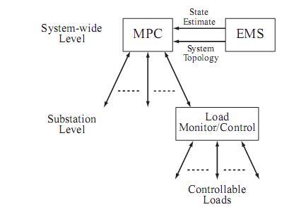
Figure 1 – Hierarchical load control structure
B. Load consolidation
The distributed nature of non-disruptive load control implies a need for a hierarchical control structure, as suggested in Fig. 1. A lower (substation) level controller is required to coordinate the many small controllable loads. In standby mode, this controller would continually poll loads to track availability of controllable load. Appropriate communications technology is described in [5]. Information retrieved from individual loads would include its real and reactive power demand, and an indicator of its load type. Using this latter information, the cold pickup behaviour of the load could be estimated. The lower-level controller would therefore build a consolidated picture of the load available to be tripped, and the likely consequences of re-energization.
Load availability information would be passed to the higher- level controller described in Section III. When a load change was required, the higher level controller would specify the de- sired amount. The substation-level controller would implement that request by signalling the individual loads. The anticipated and actual load responses may differ. That information would again be coordinated at the lower level and passed to the higher level in preparation for further control action.
3 WIDE-AREA CONTROL
A. Local undervoltage load control
Load control provides an effective means of alleviating voltage collapse. For example the cascading failure of the North American power system in August 2003 could have been avoided by tripping a relatively small amount of load in the Cleveland area [6]. The most effective load shedding strategies are not always so obvious though. Low voltages often provide a good indication of locations where load shedding would assist in relieving system stress [7]. However counter-examples are easy to generate. The simple system of Fig. 2 provides an illustration.
Consider the situation where the power being exported from Area 1 to Area 2 overloads the corridor between buses 1 and 2. (This may be a consequence of line tripping between these buses.) As a result of the overload, lines forming the corridor will demand high levels of reactive power, causing voltages at both end buses to fall. Undervoltage load shedding at bus 1, without a matching reduction in Area 1 generation, would lead to an increase in power flow over the troublesome corridor. This would exacerbate the line-overload situation. Undervoltage load shedding at bus 2 would probably achieve its desired goal. Clearly situations arise where a coordinated approach to load shedding is required. A range of such load shedding schemes have been proposed and/or implemented, see for example [8], [9], [10]. This paper suggests an approach based on model predictive control.

Figure 2 – Illustration of inappropriate undervoltage load shedding
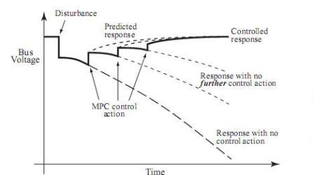
Figure 3 – MPC response
B. Model predictive control
Model predictive control (MPC) is a discrete-time form of control, with commands issued at periodic intervals [11], [12]. Fig. 3 illustrates the MPC process. Each control decision is obtained by first estimating the system state. This provides the initial condition for prediction (simulation) of subsequent dynamic behaviour. The prediction stage is traditionally for- mulated as an open-loop optimal control problem over a finite horizon. The solution of this optimal control problem provides an open-loop control sequence. MPC applies the initial control value from that sequence. The process is repeated periodically, with the state estimator giving a new initial condition for a new prediction (optimal control) problem.
The optimization problem underlying MPC involves open- loop prediction of system behaviour. Actual behaviour invari- ably deviates from that predicted response though. However feedback is effectively achieved through the correction applied when the next MPC control signal is issued. This is illustrated in Fig. 3.
Power system dynamic behaviour often involves interactions between continuous dynamics and discrete events, particularly during voltage collapse when many discrete devices switch. Formulation of optimal control problems for such hybrid behaviour is fraught with technical difficulties. However it is shown in [13], [14] that this problem may be approximated, through the use of trajectory sensitivities, as a linear (time- varying) discrete-time optimal control problem. Such formu- lations are explored more thoroughly in [15].
4 EXAMPLE
The small system of Fig. 4 is well established as a bench- mark for exploring voltage stability issues [7], [16], [17]. An outage of any one of the feeders between buses 5 and 7 results in voltage collapse behaviour. This is illustrated in Fig. 5 for a line outage at 10 seconds. In response to the line trip, voltages across the right-hand network dropped. This caused load tap changers (LTCs) to respond in an attempt to restore load bus voltages. However tap changing actually drove voltages lower, resulting in voltage collapse.
Two situations were considered, 1) no over-excitation lim- iter (OXL) on generator 3 (solid red curve), and 2) inclusion of an OXL on generator 3 (dashed blue line.) Both exhibit un- desirable voltage behaviour, though the OXL clearly induced a more onerous response. The OXL ensures that reactive demand does not rise to a damaging level, but in so doing reduces voltage support.
The studies presented subsequently explore the MPC mode detail required to achieve adequate control. To enable this comparison, the system was modelled precisely. A sixth order model (two axes, with two windings on each axis) [18] was used for each generator, and IEEE standard models AC4A and PSS1A for all AVRs and PSSs respectively. The OXL model was taken from [17]. A standard induction motor mode [17] was used for the industrial load at bus 8, and a static voltage dependent representation for the bus 9 load. The AVR of transformer LTC3 was represented by a model that captured switching events associated with deadbands and timers [19].
In all cases MPC was set to run every T = 50 seconds, with an horizon time of 2T = 100 seconds. The control objective was to restore the voltages of buses 6 and 8 above 0.98pu by shedding minimum load at buses 8 and 9. (These two sets of buses were chosen to avoid symmetry between load- shed buses and voltage-regulated buses.) This objective was achieved by solving an LP optimization problem for the load control signals. Full details are provided in [14].
A. Perfect MPC model
This initial investigation considered the ideal (though un- realistic) situation where the internal MPC model exactly matched the real system. The voltages at the regulated buses are shown in Fig. 6. It is apparent that in response to the initial MPC load control command, both voltages rose above their specified minimum values. The initial MPC command there- fore over-compensated for the collapsing voltages by shedding too much load. This was a consequence of approximations introduced to achieve a tractable LP optimization problem [14]. The voltage overshoot was corrected with the second MPC control command though, with the bus 6 voltage falling to its lower limit of 0.98 pu. At this step all of the bus 9 load was actually restored; see Fig. 7 for the load shedding commands. Note that negligible MPC action was required beyond the second control interval.
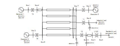
Figure 4 – Voltage collapse test system
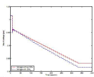
Figure 5 – Voltage behaviour without MPC
B. Realistic implementation
It is unrealistic to expect that the MPC controller could maintain a complete, accurate system representation. To inves- tigate this case, the MPC internal model was altered to make use of a simplified generator representation. Also the OXL was removed from the MPC model. Furthermore, load uncer- tainty was incorporated by introducing random discrepancies between the MPC control signals (desired load change) and the actual implemented load variation. Voltage response and load control signals are shown in Figs. 8 and 9 respectively. It is apparent that model approximation did not adversely affect the quality of MPC regulation.
These results are encouraging, though certainly not defini- tive. The degree to which MPC can tolerate model inaccuracy is core to practical power system implementation. This is the focus of on-going research.
5 CONCLUSION
Many consumer installations include components that can be tripped with negligible short-term effects. Consolidation of such load fragments provides a non-disruptive load control capability that can be used to alleviate voltage collapse. The paper suggests a hierarchical control structure which consists of a lower-level controller (consolidator) that communicates with loads, together with a higher-level controller that formu- lates coordinated responses to threats of voltage instability.It has been shown in the paper that model predictive control (MPC) provides a very effective higher-level control strategy.

Figure 6 – Voltage behaviour, perfect MPC model

Figure 7 – Load control signals, perfect MPC model

Figure 8 – Voltage behaviour, approximate MPC model
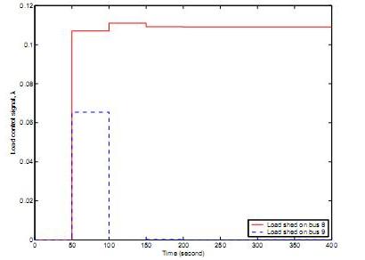
Figure 9 – Load control signals, approximate MPC model
REFERENCES
1 B. Williams, W. Schmus, and D. Dawson, “Transmission voltage recov- ery delayed by stalled air conditioner compressors,” IEEE Transactions on Power Systems, vol. 7, no. 3, pp. 1173–1181, August 1992.
2 E. Agneholm and J. Daalder, “Cold load pick-up of residential load,” IEE Proceedings: Generation Transmission Distribution, vol. 147, no. 1, pp. 44–50, January 2000.
3 J. Eto, C. Goldman, G. Heffner, B. Kirby, J. Kueck, M. Kintner-Meyer, J. Dagle, T. Mount, W. Schultz, R. Thomas, and R. Zimmerman, “In- novative developments in load as a reliability resource,” in Proceedings of the IEEE PES Winter Meeting, vol. 2, New York, January 2002, pp. 1002–1004.
4 A. Agogino, “Intelligent commercial lighting: demand-responsive condi- tioning and increased user satisfaction,” UC Energy Institute, Berkeley, CA, 2005.
5 D. Backer, “Technologies for fast load control,” in Proceedings of the IEEE PES Winter Meeting, New York, January 2002, pp. 999–1000. 6 U.S.-Canada Power System Outage Task Force, Final Report on the August 14, 2003 Blackout in the United States and Canada: Causes and Recommendations, April 2004.
7 C. Taylor, “Concepts of undervoltage load shedding for voltage stability,” IEEE Transactions on Power Delivery, vol. 7, no. 2, pp. 480–488, April 1992.
8 S. Arnborg, G. Andersson, D. Hill, and I. Hiskens, “On undervoltage load shedding in power systems,” Electrical Power and Energy Systems, vol. 19, no. 2, pp. 141–149, 1997.
9 T. Van Cutsem and C. Vournas, Voltage Stability of Electric Power Systems. Kluwer Academic Publishers, 1998.
10 C. Moors, D. Lefebvre, and T. Van Cutsem, “Load shedding controllers against voltage instability: A comparison of designs,” in Proceedings of the 2001 IEEE Porto Power Tech Conference, Porto, Portugal, September 2001.
11 J. Rawlings, “Tutorial overview of model predictive control,” IEEE Control Systems Magazine, vol. 20, no. 3, pp. 38–52, June 2000.
12 R. Findeisen, L. Imsland, F. Allgfi ower, and B. Foss, “State and output feedback nonlinear model predictive control: an overview,” European Journal of Control, vol. 9, pp. 190–206, 2003.
13 M. Zima and G. Andersson, “Stability assessment and emergency control method using trajectory sensitivities,” in Proceedings of the 2003 IEEE Bologna Power Tech Conference, vol. 2, Bologna, Italy, June 2003, pp. 219–225.
14 I. Hiskens and B. Gong, “MPC-based load shedding for voltage stability enhancement,” in Proceedings of the 44th IEEE Conference on Decision and Control, Seville, Spain, December 2005.
15 Y. Lee, B. Kouvaritakis, and M. Cannon, “Constrained receding horizon predictive control for nonlinear systems,” Automatica, vol. 38, pp. 2093– 2102, 2002.
16 C. Taylor (convenor), “Modeling of voltage collapse including dynamic phenomena,” CIGRE TF38-02-11, Brochure No. 75, 1993.
17 P. Kundur, Power System Stability and Control. EPRI Power System Engineering Series, McGraw Hill, 1994.
18 P. Sauer and M. Pai, Power System Dynamics and Stability. Upper Saddle River, NJ: Prentice Hall, 1998.
19 I. Hiskens, “Power system modeling for inverse problems,” IEEE Transactions on Circuits and Systems I: Regular Papers, vol. 51, no. 3, pp. 539–551, March 2004.