Abstract—A modified method to determine rotor-bar-iron resistance in three-phase copper casted squirrel-cage induction motors is presented in this paper. It is necessary to elaborate a new method to determine this resistance because values of different rotor parts have another ratio in copper casted rotor, e. g. value of electrotechnical iron sheet resistance is significance to value of rotor-bar-iron resistance. The author’s model presented at ICEM’96 is not dequate to this type of rotor. So it is proposed a new physical model of rotor, a new equivalent circuit, a new system of differential equations and a solution of them in the paper. There are presented the results of experimental determination of rotor-bar-iron resistance in copper casted rotors and for comparison aluminium casted rotors by different methods among other the modified method, too. It is done the analysis of test results and an estimation of modified method to determine rotor-bar-iron resistance in copper casted rotors in the paper.
Index Terms—squirrel-cage induction motor, transverse resistance of copper casted rotor.
1. INTRODUCTION
Experimentally determined value of rotor bar-iron resistance can be used both to calculate the losses in rotor particularly stray load losses and to assess effectiveness of applied rotor casting. The value is especially interested in a new technology of casting e. g. copper casting when the value is not known yet.
But the known methods are not sufficient in this case because of different ratio of physical rotor quantities than in rotors with aluminium cage. So it was elaborated a modified method to determine rotor bar-iron resistance in rotor with copper casted cage. The modification deals with Odok’s measurement method [1] improved previously by author of this paper [6] for rotor with aluminium cage.
There are presented the results of experimental determination of rotor bar-iron resistance in copper casted rotors and for comparison aluminium casted rotors by different methods among other the modified method, too.
Analysis of ring-tooth voltage drops in Odok’s method allows to assume the quality of casting.
2. METHODS AND MEASUREMENT CIRCUITS FOR TRANSVERSE RESISTANCE DETERMINATION
Measurement methods for rotor transverse resistance determination can be divided into two groups:
- methods which do not require destruction of rotor;
- methods which require destruction of rotor (removing of rings or cutting them off).
To the first group it can be taken:
A. Odok’s method [1];
B. Ding’s method [3];
C. Dabala’s method [6];
to the second one:
D. Ciganek’s method [2];
E. Christofides’s method [4];
F. Toke’s and others method [5].
A. Method
It is a practical measurement of rotor-iron-bar resistance rq made by diagram in Fig. 1.
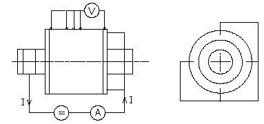
Fig. 1. Measurement diagram of Odok’s method – A.
The resistance rq is determined by formula
where:
I – total current flowed through the cage,
Z2– number of rotor slots,
lFe – length of rotor iron.
B. Method
Measurement diagram is the same as in method A. Method B takes into consideration an error caused by voltage drop on bars:
where:
VPQ – voltage drop on all the length of bar.
C. Method
The method modifies the Odok’s method. It basis on an homogeneous continuously esistivity network. This method is in detail presented in [6].
D. Method
It is the first method which requires the destruction of rotor – cutting of the rings. Measurement diagram is presented in Fig. 2.
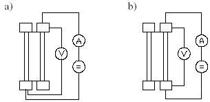
Fig. 2. Measurement diagram of Ciganek’s method – D.
The resistance of one bar and double transverse resistance between bar and slots Rc is determined by Fig. 2a). The resistance of bar Rt by Fig. 2b). The double transverse resistance is equal
Total contact resistance for surface bar unit is equal
where: c – perimeter of bar intersection; l – the rotor iron length.
E. Method
This method differs from method D in totally removing rings of cage. The wires are connected to the ends of adjacent bars by screws.
F. Method
It is improved Ciganek’s method D. The influence of bar resistance when Rm >>Rl can be presented as
when Rm < Rl it is received formula
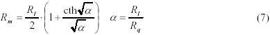
and after solution of this equation it is possible to obtain the value of Rq.
Symbols Rq, Rm, Rl correspond respectively R2p, Rc Rt in Ciganek’s method D.
3. MODIFIED METHOD TO DETERMINE ROTOR BAR-IRON RESISTANCE IN COPPER CASTED ROTORS
The modified method deals with Odok’s measurement method (Fig. 1 and Fig. 3). It is modification of Dabala’s method C in which it is taken into consideration the resistance of electrotechnical iron sheet between the bar and the shaft in case of copper casted rotor. In this method it is assumed that the cage is symmetrical and adequate physical model is a homogeneous continuously distributed parameter resistivity network (Fig. 4).
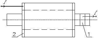
Figure 3. Measurement diagram for resistance between rotor bar and core by Odok’s method,
1 – copper band with terminal;
2 – rotor ring.
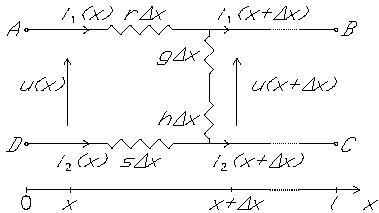
Fig. 4. Equivalent circuit for diagram on fig. 3.
Symbols: r – bar resistivity per length unit; s – shaft resistivity per length unit; g – contact conductivity per length unit; h – electrotechnical iron sheet conductivity per length unit; x – coordinate; .x – elementary section of the circuit; l – rotor iron length; i(x) – current; u(x) – voltage.
On the basis of equivalent circuit it is obtained the following system of differential equations
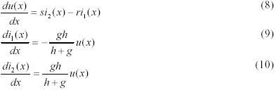
Boundary conditions are expressed as
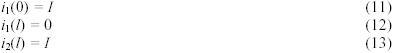
The solution of the system equations corresponding to the boundary conditions (11)-(13) are
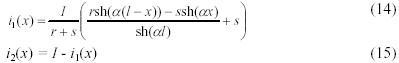
Input resistance Rm from the supply is equal
in which the voltage between the ends of the bar is equal
or in another figure
where
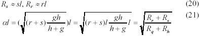
In this case the transverse resistance is equal
and electrotechnical iron sheet resistance
Additionally it is calculated the voltage UAD
There are possible some algorithms to determine transverse resistance Rq e.g. on the basis of voltages UAD, UAB or another measured voltages for which it is known the formulas. One of algorithm is presented below.
Algorithm of Rq determination in method C
1. The value of current in (18) or (19) shell be taken equal I/Qr, where: I – measured total current flowing through the rotor; Qr – number of rotor slots.
2. On the basis of measured voltage UAB, current I/Qr, and determined values of bar resistance Rr, shaft resistance Rs, electrotechnical iron sheet resistance Rh (all calculated on the basis of dimensions and material constants) it shall be determined parameter l from (18) or (19).
3. From (21) determine seeking transverse resistance Rq.
4. MEASUREMENT RESULTS
There were investigated six rotors from 4-poles, two heights of shaft (112 mm, 160 mm) motors. Three of the rotors were casted by copper and three by aluminium. The measurements were made along 7 teeth (1/4 of perimeter) of each rotor between terminals provided the current. The measurement results obtained by three non-destructive methods (A, B and C) are presented in Tab. I and on Fig. 5-8.
TABLE I Measurement Results of Rotor Bar-Iron Resistance .
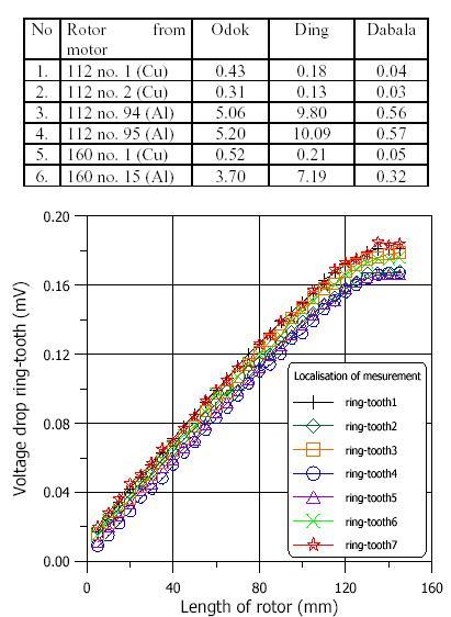
Figure 5. Voltage drop ring-tooth along rotor core of motor 112 no. 1 (Cu) for 7 teeth, current direction plus.
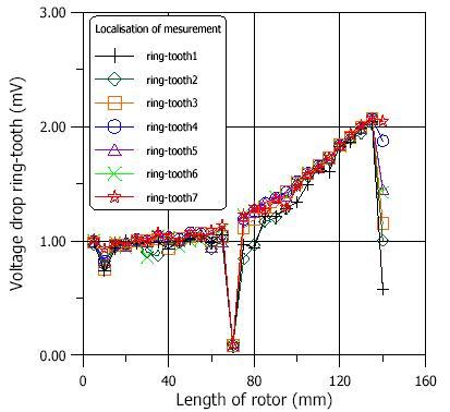
Figure 6. Voltage drop ring-tooth along rotor core of motor 112 no. 94 (Al) for 7 teeth, current direction plus (the deep drop in the middle of the rotor is caused by aluminium ring applied in this rotor)
The measurement circuit consists of direct current source galvanic generator UN=7 V and IN=600 A), ammeter with shunt for current measurement, digital voltmeter connected to computer by IEEE 488 interface and additional resistance to limit the current. The value of the current was equal 100 A. The wires was connected to the ring by four terminals from one side of the rotor and soldered to copper band fixed on shaft from the other side (Fig 1 and Fig. 3).
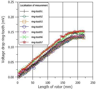
Figure 7. Voltage drop ring-tooth along rotor core of motor 160 no. 1 (Cu) for 7 teeth, current direction plus.
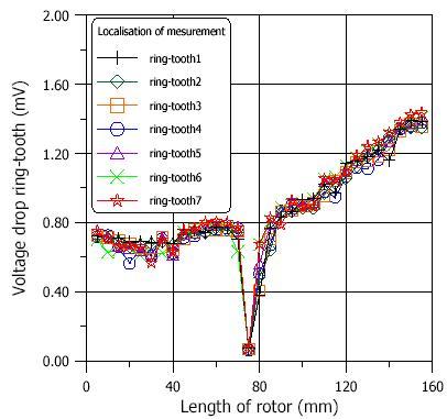
Figure 8. Voltage drop ring-tooth along rotor core of motor 160 no. 15 (Al) for 7 teeth, current direction plus (the deep drop in the middle of the rotor is caused by aluminium ring applied in this rotor).
The results (Tab. I) differ, depending on method and material of cage. Experimental-calculated Dabala’s method gives the results about 10 times less than Odok’s and Ding’s methods. However, it should be taken into consideration that in Dabala’s method it is taken real distribution of currents, instead in Odok’s and Ding’s methods only average values.
But the results from different method conclusively indicate that the transverse resistance in copper casted rotors is about 10 times less than in aluminium casted rotors.
Analysis of ring-tooth voltage drops (Fig. 5-8) shows that the runs in copper casted rotors are more smoothly and have definitely less haphazard character. It might mean that copper cages are better casted.
In the runs of copper casted rotors (Fig. 5 and Fig. 7) it is possible to see that the runs of voltage drops of particular teeth are agreed with real distribution of current (tooth no. 1 and no. 7 were the nearest the terminals with currents and they have the biggest voltage drop). This phenomenon does not exist in aluminium casted rotors (Fig. 6 and Fig. 8). The runs are mixed in this case.
In the old Dabala’s method [6] the equivalent circuit was established with assumption that Rq>>Rh. In aluminium casted rotors this condition is satisfied e.g. in rotor 112 no. 94 (Al) Rq=3.95•10(-5). (Dabala’s method) and Rh=0.06•10(-5). so Rh/Rq=1.5 %. In copper casted rotor 112 no. 1 (Cu) Rq=0.31•10(-5). (modified Dabala’s method), Rh=0.06•10(-5). and Rh/Rq=19.3 %. So, it is necessary to take into consideration the resistance Rh in the equivalent circuit for copper casted rotors.
5. CONCLUSION
The modified experimental-computational method to determine rotor bar-iron resistance in rotors with copper casted cage gives more exact results than other methods. The measurement results definitely show that the value of transverse resistance in rotors with copper casted cage is over ten times lower than in rotors with aluminium casted cage. Because the transverse resistance is less the additional losses might be bigger in copper casted rotors.
The runs of voltage drop ring-tooth show that the transverse resistance in rotors with copper casted cage has definitely less haphazard character (less deviation from the mean value) than in rotors with aluminium casted cage. It might mean that copper cages are better casted.
REFERENCES
[1] A. M. Odok, "Stray-Load Losses and Stray Torques in Induction Machines," AIEE Trans. p. III, PAS., April 1958, pp. 43-53.
[2] L.Ciganek, "Kontaktnoe soprotivlenie mezdu sterznjami aluminievoj kletki i stal'ju paketa rotora, " Vestnik Elektropromyњlennosti, No 6, 1960, pp. 40-43.
[3] F. Ding F, "Improvements for the Odok Method to Measure the Cross Contact Resistance od a Squuirrel-Cage Rotor," IEEE Trans. on Electrical Machines and Power Systems, No. 1, 1987, pp. 61-71.
[4] N. Christofides N, "Origins of Load Losses in Induction Motors with Cast Aluminium Rotors," Proc. IEE, No. 12, 1965, pp. 2317-2332.
[5] G. Toke, P. L. Timar, P. Goszti, K. Toth, G. Vincz, "Experimental Determination of Tranverse Resistivity of Cast Aluminium Squirrel-Cage," Proc. ICEM, 1982, pp. 796-799.
[6] K. Dabala, "A New Experimental-Computational Method to Determine Rotor-Bar-Iron Resistance," Proc. of ICEM, Vigo (Spain), 10-12.09.1996, vol. II, pp. 69-72.