

Duboiskyi Kirill
Faculty of mechanical engineering and machinery
Cathedra "Mechanical equipment of ferrous metallurgy plants"
Discipline "Metallurgical equipment"
Analytical study of kinematics, the development of methods of calculating energy-power parameters of the device for a quick change of submersible glasses to protect the steel from secondary oxidation during casting to slab CCM and modeling his work on the physical analogue
Scientific adviser: proff., doctor of technical science Eron'ko Sergey Petrovich
To date, metallurgical industry is one of osnovopologayuschih sectors of technological development of the country. All industries are closely related to metallurgy, which once again underlines its importance for humanity as a whole.
Every year the needs of humanity in the metal increases with speed, which requires the metallurgical enterprises to increase their own production capacity. Due to the rapid development of new technology-based and focused on high quality steel, from the "steel producers' demand high production standards, backed up by new developments in the field of smelting and further processing of steel.
One such development is qualitatively affect the final product of metal production is - "Manipulator for a quick change cup submerged slab caster. This manipulator is designed to increase mass production with continuous casting of steel and implementation of its protection from secondary oxidation, as well as to reduce the complex, routine maintenance staff.
Increasing seriality continuous casting of steel and implementation of its protection from secondary oxidation is essential for the improvement of performance of technical and economic efficiency of high-quality continuous casting [1].
Increased steel, spreads on the standard grade and slab casters, involve a number of difficulties associated with ensuring the stability of the velocity of the molten metal from the tundish into the mold and screening melt jet from the surrounding atmosphere. In this case, the constancy of flow rate were supported either by the use of glasses with a calibrated dosing channel, or using the locking system in combination with submerged glasses. In the course of a long casting shape and size of channel metering and protective glasses for several reasons can vary greatly, which leads to deterioration of the jet formation and violation of speed limits expiration of steel [2].
The most effective measure to eliminate these negative phenomena, we should recognize equipment tundishes continuous casting machines with special devices such as gate, allowing to carry out the replacement of worn refractory glass almost without interrupting the stream. Among the developers of such systems, filling the lead position occupied by foreign firms Interstop, Vesuvius, Flogates, Danieli, actively promoting their products to the markets of the CIS metallurgical equipment. It should be noted the fact that buying imported devices for metered overflow of metal from the tundish, domestic manufacturers have become dependent on a particular supplier of refractory products, as each Filling System is designed for complete set of glasses of a special design, material, shape and dimensions are protected by patents.
In order to unify the elements of the bottling equipment and the use therein of ceramic products of domestic manufacture, at the Department of Metallurgical Equipment ferrous metallurgy plants (MOZCHM), Donetsk National Technical University of taking into account the results of a comparative analysis of advantages and disadvantages of the known foreign analogues designed and engineered systems are rapidly changing metering and protective glasses, which have design features through which simplifies maintenance and operation of the overflow devices dosage tundish steel grade and slab caster.
As you know, in these systems, the most important structural part of a site clamping a removable cup to the base refractory block. This node in the tundish of foreign firms includes two groups of rocker mounted on axes symmetrically on both sides of the fireproof glass along the direction of its possible movement. In addition, each arm with one end presses on the back of the steel shell glasses by compressive forces twisted or Belleville springs acting on the opposite end of the rocker. Such a scheme host of pressing refractory element rolling requires careful selection for all of the springs to ensure the permanence of their elastic characteristics, which should be regularly monitored on special stands, previously performing with the complete disassembly of the bottling unit.
In the systems offered a potential customer such foreign firms as Interstop, Figure 2.1. And Vesuvius, Figure 2.2, the replacement of the submerged nozzle is performed in two stages.
Fig. 2.1 — Manipulator for a quick change of submersible cup firm «Interstop»

Fig. 2.2 — A device for quick change of dip cups firm «Vesuvius»
Successful implementation of slab casting billets long and very long series of demands not only of high quality refractory dip cups, but special devices to ensure their quick replacement without interrupting the stream of metal flowing out of tundish into the mold [2 - 4].
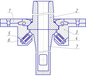
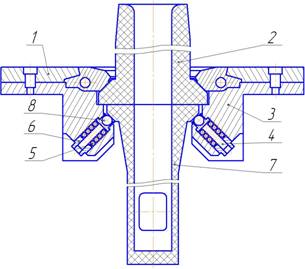
In order to remedy the deficiencies noted by the authors was developed complex, including filling and handling systems, coordinated functioning of a given program. The mechanical part of the proposed filling of the system shown in Fig. 3.1, differs from their foreign counterparts so that power the hydraulic cylinder is directly connected with it are not as well placed permanently on the manipulator. In addition, changes in the design of the site pressing submerged nozzle to the base of refractory plate. A glass of its metal clip is based on the commercials that urge springs placed in inclined channels, which are screwed from the outside threaded tube. The use of rolling elements in the reference site has reduced the power of resistance movements submerged nozzle and reduce the intensity of wear of contact surfaces of interacting elements filling device.

Fig.3.1 — Layout of the submerged nozzle in the filler system, slab caster tundish: 1 — submersible glass, 2 — tube with thread 3 — spring, 4 — roller bearing, 5 — pouring a glass, 6 — the base plate, 7 — Body 8 — receiving skids

Fig.3.2 — Handling system for fast change of dip cups

Fig.3.3 — Sequence of operations to replace the submerged nozzle


Fig.3.4 — Diagram of a docking station: 1 — hydraulic power cylinder, 2 — cap 3 — spring-loaded capture; 4 — body filler system, 5 — clamp handling system

Fig.3.5 — The operating principle of the mechanism paralellogramnogo minipulyatsionnoy system (animated gif, repeating cycles —1, the volume 886kb)
For the normal functioning of the
linkage of the proposed manipulator is necessary to ensure the required ratio
of its linear and angular parameters under which the system in the interaction
of articulated elements are not there is a rupture in the kinematic chain.
In
order to obtain baseline information needed to compile the program that
implements a mathematical model for calculating the parameters of the device,
taking into account the recommendations of [6] performed an analysis of the rod
mechanism, in accordance with the scheme shown in Fig. 4.1.
In the
joint motion, owned by rocker AB (link 1), there is a circle, which describes
the system of equations:
 ,
,
where
Movement
of the hinge D, owned crank CD (link
2), occurs in a circle, described by a system of equations:
 .
.
Proceeding
from the conditions of a closed loop ABDC, you can write:
 ,
,
where
3 relative to the
crank arm 2.
Since
the four-ABDC in accordance with the proposed kinematic scheme is a
parallelogram, then lCD = lAB, lAC = lDB,
φ2 = φ1.
Using
the parallelogram provides plane-parallel motion lever
![]() .
.
The
equations obtained from the condition of closed-loop ABDC, to mean:

or
 .
.
Movement
of the hinge H, belonging-drawn EH (link 4), there is a circle, described by a
system of equations:
 ,
,
then the condition of a closed contour CDFHE:
 ,
,
In the
system of equations obtained from the condition of closed-loop CDFHE, there are
three unknowns: lEH, φ4, φ45, therefore, reduce
it to:
 ,
,
then
 ,
,
where φ35 — angle lever 5 with respect
to the lever 3.
The rotation angle thrust 4 can be found from the
triangle of EHF by the cosine theorem:
![]() ,
,
from
 ,
,
where
![]() ;
;
then
![]() ,
,
![]() .
.
From
the results of the analysis equations that the problem of synthesis of this
linkage is reduced to determining the length of rod 4 and the coordinates of
the location of a glass, depending on the angle of rotation of the crank 1.
The
solution of these equations must perform for the range of crank angle φ2
'from 0 to 75 °. in the opposite direction of the frame shown in Fig. 4.1:
![]() .
.
This
allows for performing the analysis to exclude no solution. In the initial state
of the rod mechanism (φ2 '= 0 ° deg.) Level of 5, marked by points FZ,
representing the axis of symmetry of the submerged nozzle, should be in a
horizontal position. As seen from the kinematic scheme, it is possible,
provided that:
![]() .
.
where φ5 = const — the angle between parts of the HF and FZ-level 5
(see Fig. 5.1).
In the final position of the rod mechanism (φ2 '=
75°) symmetry axis of the cup should be in an upright position. In this
condition:
![]() о,
о,
The
geometrical parameters of the robot arm mechanism imposed restrictions
associated with the extracted space (maximum height of the stand arm, the
distance between the outer surface of the bottom of the tundish and the upper
part of the caster mold, the distance from the manipulator tundish, etc.).
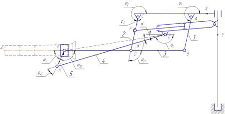
Fig. 4.1 -
The scheme of study of the rod mechanism
Based
on these expressions, a program in MathCAD environment for the synthesis of the
rod mechanism, the geometric parameters and simulation of its work when you
turn the crank at an angle φ2 'from 0 to 75o [7].
The
initial data taken by the coordinates of supports A and E, the length of links lAB, lCD, lDB, lDF, lHF, angle
φ5. Solving the system of equations in which the indices n and k denote
the initial and final coordinates of the points
 ,
,
where
 ,
,
determine the length of the rod 4 as a function lEH = f
(φ5), providing the desired trajectory of motion lever 5 and the bracket
with a glass.
The
success of the device for quick change of dip cup to a large extent depends on
the correct and informed choice of its kinematic and energy-power parameters.
In previously published work [5] reported the results of studies of the
kinematics casting tundish systems designed for the
implementation of artificial replacement of the spent ceramic products backed
with no overlap of filling the channel.
This
paper presents the method of calculation of power parameters of the hydraulic
drive and support assembly of this device class, the structural scheme is shown
in Fig. 5.1.1.
a
b
Fig.5.1.1—
Diagram of the change of dip cup
The device
includes a prefabricated metal building, equipped with means for fixing to the
flange, welded to the outer surface of the bottom of the tundish.
Frame of the device consists of a mounting plate 1, having a central hole,
which houses the lower part of the nest two monoblock
tundish. With mounting plate rigidly connected are
arranged symmetrically to its longitudinal axis of the two guides of the
support 3 carrying a removable heat-resistant glass Immersion
During the
operation tundish tundish
caster at its elements are static and dynamic loads, numerical values can
vary significantly depending on the application of the developed mechanical
system. In accordance with the computational scheme, static resistance force,
impede the movement of fire-resistant glasses are due on the one hand the
friction arising at the contact surfaces of glasses, as well as its reference
site between a metal clip submerged nozzle and clamping pins or rolling bodies,
On the other hand - an additional burden associated with the destruction of the
layer deposition of aluminum oxides or crust solidified metal on the walls of
the channel.
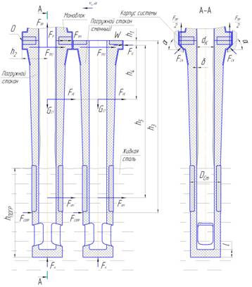
Fig. 5.1.2—
Scheme of forces acting in the bottling system
With this
in mind, the total force of technological resistance W,
occurred when replacing the submerged nozzle is equal to:
![]() , (1)
, (1)
where Fp — the power of
resistance, which occurs during fracture layer of sediment in the channel of
the glass;
Ftr1
- break-open tensions between the working surfaces of the ceramic elements
filling device (replaced submerged nozzle);
Ftr2
- the friction between metal surfaces in the reference site filling device;
Ftr3
- the force of friction between working surfaces of the metallic elements
foster sled shell and a removable dip cup;
Fsopr - force due to drag immersed in a liquid metal is
part of the glass (being replaced and the replacement), when it is moved;
Fis - inertia cups (replaceable and removable);
Fim — the force of inertia of the liquid metal in a
submerged part of the channel submerged nozzle (the replaced and replacement).
To determine the value of the force Fp, you can use the dependence given in [6]:
![]() (2)
(2)
where K1 -
coefficient equal to the ratio of maximum shear resistance to the tensile
strength of the material produced crusts;
σv — tensile strength of steel at a given
temperature;
Sp — cross-sectional area cut off crusts:
![]() (3)
(3)
dc — the
channel diameter submerged nozzle;
δ — thickness of the resulting metal peel.
The force of friction between working surfaces of
ceramic elements:
![]() . (4)
. (4)
The force of friction between metal surfaces in the
reference site:
![]() . (5)
. (5)
When applied to the reference site of rolling
resistance force is determined by the formula:
 . (6)
. (6)
The force of friction between working surfaces of
metal elements foster sled shell and a removable dip cup:
![]() . (7)
. (7)
In these
expressions μp — coefficient of friction of refractory refractory; μs
— coefficient of friction of steel on steel; f — coefficient of rolling
friction; dkach - diameter of the rolling bodies; Fpr - the force of pressing the submerged nozzle for
refractory nested block; Fszh — elastic force
developed by Blocks spring support assembly and connected with a force pressing
the dependence Fszh =.
In accordance with the recommendations of [6], the
values of
the quantities in equation (2) — (7), the calculations can be taken: μp
= 0,3 - 0,7; μs = 0,15 - 0,18, k1 = 0,7 - 0,8; σv
= 50 - 60 MPa; δ
= 5 -
Force due to drag immersed in a liquid metal part of
the cup when it is moved:
![]() , (8)
, (8)
where c =
0,4 — drag coefficient;
ρs
— density of liquid steel at a given temperature casting;
SCT - the area of greatest
cross section of glass in a plane perpendicular to the direction of motion;
v0 - velocity of glasses in the
liquid steel.
In accordance with Fig. 5.1.2:
![]() ,
,
Dst
- external diameter of the immersed part of the glass;
hpogr
- depth of glass in molten steel.
The velocity of the cup relative to the metal in the
mold with a triangular plot of motion:
![]() ;
;
where lp - the
length of the plate submerged nozzle in contact with the nesting block tundish;
td - time for which shall replace the submerged
nozzle.
Inertial forces are replacing and glasses of Fis and replacement of the liquid metal Fim,
located in the submerged portion of their channel:
![]() , (9)
, (9)
![]() . (10)
. (10)
Here mst
mM and - respectively the mass of the submerged
nozzle and the metal in buried parts of its channel, AST = s - acceleration of
the glass, developed by the drive at its replacement:
![]() ,
,
where tр - the dispersal of the glass, equal
to 0,5 • tз.
The
friction force calculated by (4) — (6), due to pressing force Fpr whose values should be
set out conditions to prevent formation of the gap between the contact working
surfaces of refractory elements as a result of joint action to dip his cup of
gravity Gst, the Archimedes force FА, forces inertia of the cup Fis and situated in the recessed portion of the channel the
liquid metal Fim, the drag force cup Fsopr and disjoining forces resulting from the time of the
destruction of metal cover.
Push rod
drive hydraulic cylinder replacement glass affects the casting replaceable element,
overcoming resistance by the technological W. Since the vector shearing force Fts is located below the slip plane of the working surface
replaced the glass on the distance h1, the couple of forces, causing its
rotation about a horizontal transverse axis passing through the point O. This
is turn helps power Gst, and prevent the forces FА, Fis, Fim, Fsopr .
No gap
between the contact work surfaces and a basic candy bar protective glasses will
be guaranteed if:
![]() .
.
Whence, considering (1) and (4) — (7):
![]() .
.
The total force developed by one unit spring support
assembly tundish:
![]() .
.
Force provided by each spring at the operating strain,
corresponding to the largest forced compression screw-cap, is determined by the
formula:
![]() ,
,
where n
— the number of springs in one block of the reference site.
Process
of interaction between a fast-moving rod drive hydraulic cylinder with a
removable dip cup set by the nature of the percolation is close enough to a
completely inelastic collision, since all elements of the system after exposure
to move as one. In this case, the colliding bodies having elastic-plastic
deformations, because of what part of the kinetic energy of the system is converted
to its internal energy, is not used to doing work in bridging technology loads.
Since the definition of theoretically share lost kinetic energy in studying the
behavior of non-free body, which is pushing for a submersible glass is not yet
possible, the necessary information obtained as a result of experimental
studies. Control measurements performed on laboratory benches on the developed
techniques, the detailed descriptions in [6, 7] showed that the mechanical systems,
such devices quick replacement of protective glasses, the proportion of impact
energy expended in overcoming resistance to the movement of non-free body,
depending on the strength of pressing it is 30 - 50%, and the shock load at the
time of launch system from the rest is 25 - 30% of the total force of
technological resistance. Therefore, the resulting estimated value of the total
load on the drive including the friction force at the nodes of the bottling
system and the force required to break the layer of deposits in its channel, as
well as inertial forces should be adjusted upwards by introducing a correction
factor that takes into account the established loss of input energy expended on
the deformation of colliding elements investigated device.
With that said, the peak force Fts
you want to create a drive hydraulic cylinder to overcome the technological
resistance should be determined from the expression:
![]() ,
,
where k 2 = 1,2 ... 1,3 — a correction factor
that takes into account the loss of the supplied energy to the deformation of
interacting elements bottler system.
Using the calculated value of Fts, when selected from the standard number of working
pressure p developed by pump oil station, find the power cylinder piston
diameter:
![]() .
.
For the
convenience of using the proposed method of calculating the parameters of rapid
change jars were immersed in the program application package MathCad.
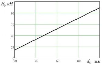
Fig.5.1.3—
power drive cylinder depending on the internal
diameter
of the cup
At fig.5.1.3 shows the variation of the force Fts created by driving a hydraulic cylinder, depending on
the internal diameter of the cup at the depths of his immersion in the metal
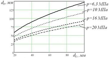
Fig. 5.1.4—
Bore cylinder depending on the internal
diameter
of the cup
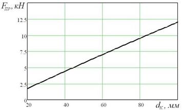
Fig.5.1.5—
force pressing the submerged nozzle depending on the internal
the
diameter of its channel
Thus,
the method of calculation allows to determine the force
parameters of the hydraulic drive and support assembly device for quick
change of dip cups, ensuring stability of serial casting.
On
elements of the lifting mechanism is the console of Fig. 6.1 Gravity
parallelogram linkage system Gp, staples - restraint
submersible fire-resistant glass Gsk, submersible
fire-resistant glass Gstk and part of the gravity of
the weight of the cylinder Gtsil.
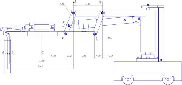
Fig. 5.2.1—
Vertical
reactions in the jointsare determined from the the equation :
![]()
![]()
 ;
;
![]()
![]()
 ;
;
![]()
![]()

![]()
![]()

The equation sums of moments of forces preodalevaemyh hydraulic, is as follows:
![]()
![]() +
+![]() .
.
Moments of
friction in the hinge pillars:
![]() ,
, ![]() ,
,
![]()
![]()
where -
coefficient of friction in the hinge support.
Then an effort to stem gidrootsilindra
provided that ![]() =
=![]() =
=![]() =
=![]() = r,, is:
= r,, is:
![]()
The submission of the above scheme, the power
calculation, we can determine the necessary efforts to hydraulic cylinders. Further,
the data obtained to choose from a catalog of standard hydraulic cylinders that
model whose characteristics as close to the settlement.
The main parameters of the
piston cylinder are as follows: piston diameter D and stem d, the working
pressure P, and stroke S.
Consider the cylinder piston rod with a one-sided
(Fig. 6.1).
Fig.
6.1. - Basic and design parameters of the hydraulic
cylinder
On the basic parameters can be determined following
dependencies:
area of the
piston in the piston cavity of a
![]() ,
,
The area of the rod in
the piston cavity 2
![]() ,
,
Force developed by hydraulic cylinders under his / her
nomination
![]() .
.
Force developed by hydraulic cylinders to pull-in
![]() ,
,
where kтр
= 0,9 ... .98 - coefficient accounting for losses due to friction;
Required flow rate in the nomination and pull-rod,
respectively:
![]()
![]()
where ![]() volumetric efficiency of the cylinder;
volumetric efficiency of the cylinder;
u - velocity of the rod, which is equal to the
private, stroke and duration of change surgery glasses;
Strength
calculations determine the thickness of the walls of the cylinder, the
thickness of the cap (head) of the cylinder, rod diameter, the diameter of pins
or bolts for fastening the covers.
Depending on the ratio of DH outer and inner
cylinder diameter D is divided into thick and thin. Thick-walled cylinders is
called, in which DH / D> 1,2, and thin-walled —
cylinders in which the DH / D 1,2.
Wall
thickness of a single-layered thick-walled cylinder is given by:
where Pу
- nominal pressure equal to (1,2 ... 1,3) P;
[σ]
- allowable stress in tension, Pa (2.5 for iron, 107 for ductile iron
4107, for steel castings (8 ... 10) 107 for Alloy Steel (15 ... 18), 107 for bronze,
4.2 10 7); μ - coefficient of transverse strain (Poisson's
ratio), equal to cast 0, 0.29 for steel, aluminum alloys for 0.26 ... 0.33,
0.35 for brass;
For some
of the formulas of the cylinder wall thickness is added to the processing of stock
material. For D = 30 ...
The
thickness of the bottom of the cylinder is determined by the formula:

where k — coefficient depending on the shape of
the bottom, equal to k = 0.25;
![]() - Allowable stress equal to = 20MPa;
- Allowable stress equal to = 20MPa;
c
- increase in the processing of the inner diameter of
the cylinder, which is equal to =
Determine the diameter of bolts for fastening the
covers of cylinders:
![]()
where ![]() the allowable stress in tension, the bolt of
steel
the allowable stress in tension, the bolt of
steel
n -
number of bolts;
According to the results of calculations from Table 2
cylinder select GCC 70.160.16.000 with the following parameters:
- Piston
area ratio = 1.45,
- Piston
diameter - D =
- Rod
diameter - d =
- Stroke
- S =
- Maximum speed - V =
-
Nominal pressure = 20 MPa,
- Nominal maximum pressure = 25 MPa.
Designed device, due to the novelty inherent technical solutions aimed at simplifying the operation and reliability of casting tundish systems casters can compete with foreign counterparts, or supplied to the markets of the CIS metallurgical equipment.
In writing this essay master's work is not completed yet. Final completion: December 2011. Full text of the materials on the topic can be obtained from the author or director after that date.