Abstract of the Master’s Qualification Thesis
RESEARCH OF INTEGRITY ENHANCEMENT METHODS FOR DIGITAL SIGNALS DETECTION USING PLL-BASED DEMODULATORS
Timeliness. Signals recovery is very important practical task for modern telecommunications. It is achieved by demodulators. In this work we’ll consider PLL based demodulators. Presence of noise in the channel leads to the impairment of the signal and information bits loss during the locking time.
Research objective – bit loss reduction, development of FM demodulator and integrity improvement of digital signals detection.
Research tasks:
- research the existing PLL schemes, identify their advantages and disadvantages;
- develop PLL scheme which combines advantages of examined schemes;
- integrate new scheme into FM demodulator and compare it with another demodulators;
- draw a conclusion about integrity enhancement for digital signals detection using PLL demodulator.
Scientific Innovation. The scientific innovation of this work is the development of new PLL scheme which combines advantages of analogue and digital PLLs.
There are analogue and digital PLLs. Analogue PLLs are more noise-resistant but they have narrow capture range and long locking time. Digital PLLs have wider capture range and shorter locking time.
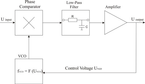
PLL structure is shown in fig. 1.

PLL consists of phase comparator, low-pass filter (LPF), amplifier and voltage-controlled oscillator (VCO). The phase of output signal is related to the phase of input “reference” signal. The circuit compares the phase of the input signal with the phase of the signal derived from VCO and adjusts the frequency of VCO to keep the phases matched. Consequently, the phase and frequency of output signal equal the phase and frequency of input signal. This feature is used for demodulation.
Phase comparator compares the phase of the input signal with the phase of the signal from VCO. Analogue phase comparator is a multiplier. Digital phase comparator is constructed on two D-flip-flops and “NAND” element (fig. 2).

Low-pass filter is used for signal filtration and attenuation parasitic components from its spectrum. When the pass band of the LPF is wide noise will also pass through the filter. When its pass band is too narrow the quality of signal will be unsatisfactory. This contradiction can be solved by non-linear filters. The structure of such filter is shown in fig. 3a.

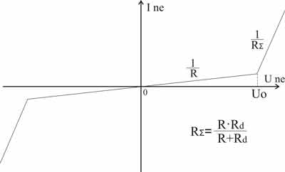
Non-linear filter consists of linear resistor, two diodes and non-linear element. The current-voltage diagram of non-linear element is shown in fig. 3b. The length of linear segment is proportional to the noise level. This filter has different width of its pass band in relation to the level of the input signal.
The research model is shown in fig. 4. It consists of non-linear element (NE), integrator and a feedback loop. C is the capacity of the capacitor.

The current-voltage diagram of non-linear element in this model is shown in fig. 5.

We investigated three types of filters: first-order linear Bessel filter, linear filter with a feedback loop and non-linear filter. Research results are shown in fig. 6. Here are three PLL modes: pulling, locking, loss of lock.

So, PLLs with non-linear filter have wider capture range and shorter locking-time but the quality of output signal is worse. There are parasitic pulsations in locking mode and the signal waveform is impaired.
We compared two types of phase comparators in this research: analogue (multiplier) and digital (based on D-flip-flops).
The research model consists of transmitter, channel with Gaussian noise and PLL demodulator. The estimation criterions are signal’s average value and mean square deviation. The research results show that analogue phase comparator is more noise-resistant. The level of its direct component doesn’t vary in response to the noise level, the fluctuations of the signal are less than those of the digital comparator.
Fig. 7 shows the phase comparator’s response to the phase jump. The phase jump occurs at 220 ms. We can see that analogue phase comparator needs more time for locking signal. Average time of transient response is 12 ms for analogue comparator and 3.4 ms for digital comparator.

So, analogue phase comparators are more noise-resistant but digital phase comparators guarantee high PLL performance.
The research model consists of transmitter, FM modulator and PLL demodulator. The input PLL signal is frequency-modulated signal. We changed VCO gain from 0 Hz/V to 30 Hz/V and monitored PLL’s ability to lock the signal.
The results shows that analogue PLL is able to lock the signal while VCO gain equals 0.1÷0.3 Hz/V. Digital PLL locks FM signal while VCO gain equals 0.05÷30 Hz/V, its output signal amplitude doesn’t vary in response to VCO gain. It means that digital PLLs have shorter locking-time than analogue.
Research of the PLL demodulator has been conducted in this part of work. We have confirmed that analogue PLLs are more noise-resistant while digital PLLs have shorter locking-time. Use of non-linear filters make quick signal locking possible but the output signal of non-linear PLL is worse than output signal of PLLs with linear filters.
So, all examined schemes have both advantages and disadvantages. It makes sense to develop a new PLL scheme which is noise-resistant and has high performance.
Note.
The thesis is unfinished. The abstract covers only present results of the research.
