Aleksey Gurov
Faculty: Computer Science and Technology
Speciality "Software engineering"
Scientific adviser: Sergey Zori
Realistic stereo visualization of three–dimensional scene using ray tracing on specialized parallel computing systems
Survey of research and developments
Backward ray tracing algorithm
Review of existing methods of optimization algorithm backward ray tracing
A review of research on the topic in DonNTU
A review of research on the topic in the world
Introduction
The development of modern technology allows us to consider today the construction of stereo images as one of the most promising areas of computer graphics. Ability of converting images to stereimages creates new directions for applied research – the creation of software and hardware virtual reality training systems built using stereo presentations and animations. There are several methods for generating realistic images, such as the direct ray tracing (tracing of photons), the inverse ray tracing, and others.
Ray tracing considered the most powerful and versatile method for creating realistic images. There are many known examples of tracing algorithm for high–quality display the most complex three–dimensional scenes. It may be noted that the universality of tracing methods is largely due to the fact that they are based on simple and clear concepts that reflect our experience of perception of the world [1].
Objects around us have in relation to light following properties:
– Emit;
– Reflect and absorb;
– Pass through it.
Each of these properties can be described by a set of characteristics. Emitting can be characterized by the intensity and spectrum. Reflection property (absorption) can describe the characteristics of the diffuse scattering and specular reflection. Transparency can be described as a weakening of the intensity and refraction. Of the surface points (volume) of the radiating objects are based on light rays. We can call such rays are the primary – they cover everything else. From sources of light comes in different directions countless primary rays. Some rays go into space, and some get on other sites. If a ray hits a transparent object, it is refracted, it goes further, with some of the light energy is absorbed. As a result of the objects of primary rays arise secondary rays. Some of them fall on other objects. So, multiply reflected and refracted, the individual light rays come to a point of observation. Thus, the image of the scene is formed by a set of light rays. Color of each pixel in the image determined by the spectrum and intensity of primary beams of radiation sources, as well as the absorption of light energy in objects encountered on the path of the rays. Immediate implementation of the ray model of image formation is difficult. You can try to construct an algorithm for constructing an image in this way. In this algorithm must be provided through all the primary rays and identify those that fall within the objects and the camera. Then run through all the secondary rays, and also take into account only those who fall into the objects and the camera. And so on. This algorithm is called the direct ray tracing. The main drawback of this method – a lot of extra operations connected with the calculation of the rays, which are then not used.
Survey of research and developments
The construction of stereoscopic images is quite an urgent problem today as the question of maximum plausibility and realism of computer images. Ray tracing is building quite realistic images, but people have a three–dimensional vision. Consequently, stereo vizualisation give a truer picture.
To date, the implementation of the trace in real time is difficult. Known attempts to create a 3D–accelerator with hardware algorithm backtrace, but widespread, they have not received due to the relatively high price and lack of speed (the speed of constructing a satisfactory image was only for images with a resolution of 640x480).
However, the computing power of personal computers are increasing every day. In the near future should see the machine on which the tracing algorithm will run in real time.Tracing should supplant other algorithms are given clear superiority in image quality and versatility of the method. but it is necessary to provide the acceleration of the algorithm and its parallel using.
Using at practice
1) Ray–tracing in the movie:
Ray tracing is used in the film industry for a long time and actually became the standard method of imaging in this area. Of course for the tasks movie requires photorealistic rendering. Speed, in principle, is not so important. It happens that the individual sequence of frames are calculated for weeks, and the frame processing takes more than 1 hour (at 24 frames per second it turns out that 1 second will be rendered 24 hours).
2) Ray tracing in games:
In computer games have a dual use of ray tracing. Calculating the irradiance map or lightmap. Usually this is done using photon maps, although there are exceptions in the form of radiosity. Almost any modern 3D game uses light maps. Lightmap – a texture in which light is drawn. It is superimposed over the scene and it turns out that the scene is illuminated. The second application of ray tracing in games – direct visualization, calculation of per–pixel images of each frame. Examples of such games can bring a little bit mainly because the number of pixels rather large and at tracing millions of rays 25 times per second is quite a challenge. Already, there are 8–core machine as a PC, computing power which, in principle, enough to render the secondary stage by the inverse ray tracing.
3) Ray–tracing in the business of selling:
Basically it is a photo–realistic rendering. Often, some items such as furniture is available in several different ways. In office chairs may be different upholstery, wheels or other parts of which are in essence you can collect the right buyer chair. However, to do this in place is not always convenient. Often much cheaper / easier to simulate those goods which the buyer wants to see. With the help of ray tracing can be virtually indistinguishable from the real picture – it is possible to make a picture of the goods which is not yet [2].
Backward ray tracing algorithm
Backward ray tracing method significantly reduces the search of light rays. The method was developed in the 80's, considered the fundamental work of Whitted and Kay. Under this method, ray tracing is not from the light sources, and in the opposite direction – from the observation point. So take into account only those rays that contribute to the formation of the image.
Plane projection is divided into many pixels. Choose a central projection with center gathering at some distance from the plane of projection. Draw a straight line from the center of descent through the middle of the pixel plane of projection. This will be the primary ray. If the beam falls into one or more objects in the scene, choose the closest point of intersection. To determine the pixel color images need to take into account the properties of the object, and then some light emittion falls on the corresponding point on the object.
If the object is a mirror (at least in part), we construct a secondary beam – beam incidence, considering the previous ray reflection, the primary beam is traced. For a perfect mirror rather then just follow the next point of intersection of the secondary beam with some object. In a perfect mirror perfectly smooth polished surface, so the one reflected ray corresponds to only one incident beam. A mirror can be darkened, that is, to absorb part of the light energy, but is still the rule: one beam falls – one reflected. If the object is transparent, it is necessary to construct a new beam, such that the refraction would give the previous traced ray. For the diffuse reflection intensity of reflected light, as is known, is proportional to the cosine of the angle between the beam from the light source and the normal. When it becomes clear that the current ray–tracing does not intersect any object and goes into free space, then this trace to the beam ends.
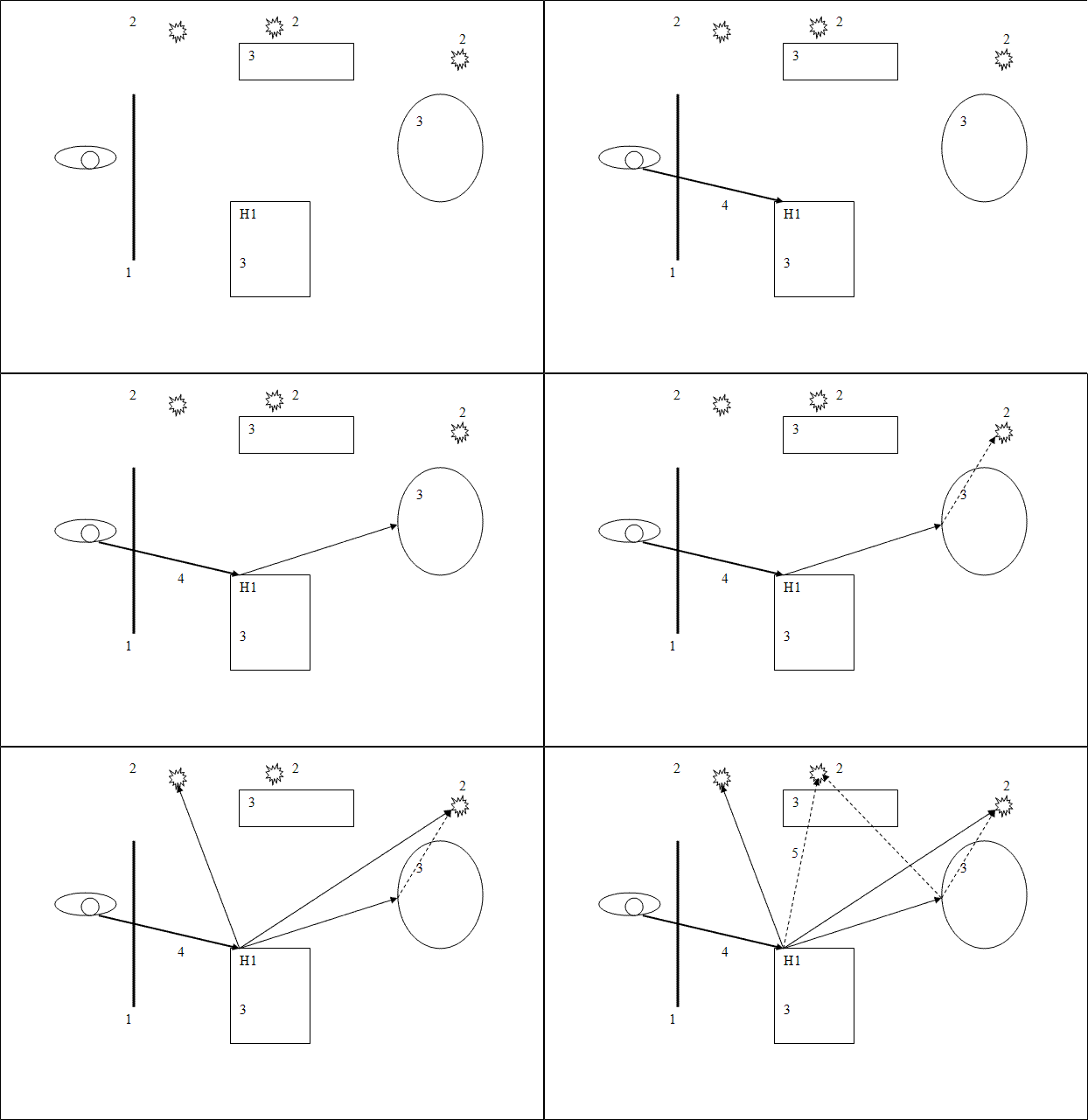
In the practical realization of the inverse trace impose restrictions. Some of them need to be able to basically solve the problem of image synthesis, but some restrictions can significantly improve the performance of the trace [2]. The algorithm is as follows: from the virtual eye through each pixel in the image beam is emitted and there is a point of its intersection with the surface of the scene. Rays emitted from the eye are called primary. Assume primary ray intersects an object 1 at H1 (Fig. 1).

Figure 1 – Visualization of the ray tracing algorithm. Animation consists of 6 shots with a delay of 1 second. Number of cycles of reproduction is limited to 5
1 – image, 2–light source, 3–object, 4 – eye ray , 5 –shadow ray
Next, you need to define for each light source is visible from it is this point. Assume for the moment that all sources are light point. Then for each point light source, before it is emitted by the shadow ray from the point H1. This allows us to say whether a given point highlights a particular source. If the shadow ray finds the intersection with other objects located closer than the light source, the point H1 is in the shadow of this source and cover it is not necessary. Otherwise, consider coverage for some local models (Phong, Cook–Torrance, etc.). Illumination from all the visible (from the point H1) consists of light sources. Further, if a material object has a reflective properties, from the point H1 is emitted by the reflected beam and for him the whole procedure is repeated recursively trace. Similar actions should be performed if the material has a refractive properties [2].
Review of existing methods of optimization algorithm backward ray tracing
There are many approaches to the optimization of inverse ray tracing algorithms. Here are some for accelerating the algorithm.
1 kd–tree
This approach to optimize the ray tracing are discussed in [3–6]. Consider the structure of the binary space partition, called kd–tree. This structure is a binary tree of bounding box, embedded in each other. Each box in kd–tree splits the plane perpendicular to one of the axes of two subsidiaries of the box. The whole scene is entirely contained inside the root of the parallelepiped, but, continuing a recursive partition of the parallelepiped, we can come to that in each parallelepiped sheet will contain only a small number of primitives. Thus, kd–tree allows you to use a binary search for finding primitive intersected by the ray. Constructing a kd–tree algorithm for constructing the kd–tree can be represented as follows. Hereinafter referred to as a rectangular parallelepiped will be called the "box" (box).
1) Add all the entities in the bounding box. Ie build a bounding box all entities that will match the root node of the tree.
2) If the primitives in the node or small tree depth limit is reached, complete the construction.
3) Choose the partition of the plane, which divides the node into two daughter. We call them left and right nodes of the tree.
4) Add the primitives that intersect with the box left node in the left node, the primitives that intersect with boxing right node to the right.
5) For each of the nodes recursively run the algorithm from step 2.
The most difficult part of building a kd–tree is the third step. It depends on the efficiency of the accelerating structure. There are several ways to choose the plane partition, we consider them in turn:
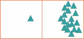
1. Choose a plane partition in the center. The easiest way – to choose a plane in the center of the box. First we select the axis (x, y or z), in which the box has a maximum size, then split the box in the center (Figure 2).
Figure 2 – Split center
This method has poor adaptability. Intuitively, one can describe the reason for poor speeds on these trees so that each node in a lot of empty space through which the ray tracing (passes through the tree during the search), while the empty space should be immediately discarded if possible
2. Choose the median plane.
You may think that it would be nice to share the node into two daughter each time so that the right and left subtree of primitives was the same. Thus, we construct a balanced tree, which should speed up the search (Figure 3).
Figure 3 – Split the median
This is not a good idea. The thing that balanced trees can help only if the required element whenever there is a random site, that is, if the distribution of rays over the nodes during the search will be uniform. In fact, it is not. Rays on the average will go more in that node, which is larger in its surface area, and at a median partition of these areas at the sites may be different.
2. Surface Area Heuristic (SAH)
What are the criteria for a well–constructed kd–tree? At an intuitive level, it really is not very clear, although the phrase "as much empty space should be discarded as soon as possible" probably fine. We introduce the function value tracking (cost traversal), which will reflect how expensive the computational resources to track this node random collection of rays.We shall calculate it as follows.
Where CostEmpty – the cost of tracking an empty site (a constant), SurfaceArea – the surface area of ??the corresponding node, and N – number of primitives in it. Need to choose a plane razbienieya so as to minimize this function. Argument of x is one–dimensional coordinate plane partition.
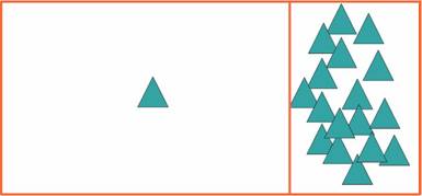
Good candidates for a minimum of SAH may serve as a boundary primitives. A simple algorithm to construct as follows. Each time you select a plane to enumerate all possible boundaries of primitives in three dimensions, calculate the value of these cost functions and find the minimum among these values. When we calculate the SAH for each plane, then we need to know N (left) and N (right) – the number of primitives on the right and left of the plane. If you compute N by a simple enumeration, in the end get the quadratic complexity algorithm for constructing [3] (Figure 4).
Figure 4 – Split based SAH
A review of research on the topic in DonNTU
In the Donetsk National Technical University of contemporary issues involved Ivanova Ekaterina, Serezhenko Alexander, Vinokurov Alex and Alexander Grishchenko.
A review of research on the topic in the world
How to optimize and accelerate the ray tracing algorithm to produce photo realistic images involved the world–known companies that specialize in the development of visual effects, creating animated films (PIXAR), companies that specialize in the development of hardware for the PC (INTEL, nVidia, AMD), a company who specialize in the development of specialized computer equipment (Caustic, Splutterfish). Due to the fact that the method of ray tracing is very picky about the hardware component, even a world leader in creating visual animated PIXAR uses this technology not for all developments so as not to overload the existing computing power. A similar situation experienced company Lucas Arts [7].
The main objectives
– To develop an optimized algorithm for ray tracing, in order to reduce computational complexity;
– modify the algorithm developed for stereo imaging;
– Explore the possibility of implementing the algorithm on parallel computer architecture, including the architecture of modern graphics cards GPU PC;
– To create a prototype software system for the synthesis of realistic stereo image using ray tracing on a parallel architecture of GPU graphics card PC to analyze the characteristics of the synthesis process in comparison with "classic" solution of the problem.
Conclusion
In the course of investigating the problem have been analyzed existing approaches to accelerate the implementation of ray tracing, revealing their strengths and weaknesses, the methods of creating a stereo image. To date, the implementation of the trace in real time is difficult.
However, the computing power of personal computers and their specialized subsystems are increasing every day. Tracing should supplant other algorithms are given clear superiority in image quality and versatility of the method. Consequently, the ability to effectively implement a realistic rate of synthesis of stereoscopic images using ray tracing and the possibility of its implementation on parallel architectures, specialized computer systems is an important task.
References
- Михайлюк М.В., Хураськин И.А. Синтез стереоизображения для систем виртуальной реальности с использованием оптической трекинговой системы.
- Трассировка лучей, МГУ, 2007 [Электронный ресурс].–Режим доступа: http://www.ray–tracing.ru/
- Shevtsov M., Soupikov A., Kapustin A. Highly Parallel Fast KD–tree Construction for Interactive Ray Tracing of Dynamic Scenes. In Proceedings of the EUROGRAPHICS conference, 2007
- Foley T., Sugerman J. KD–Tree Acceleration Structures for a GPU Raytracer. In Proceedings of the ACM SIGGRAPH/EUROGRAPHICS conference on Graphics hardware, p. 15–22, 2005.
- Horn D., Sugerman J., Houston M., Hanrahan P. Interactive k–D Tree GPU Raytracing. Proceedings of the symposium on Interactive 3D graphics and games on Fast rendering, p. 167–174, 2007.
- Popov S., Gunther J., Seidel H.–P., Slusallek P. Stackless KD–Tree Traversal for High Performance GPU Ray Tracing. In Proceedings of the EUROGRAPHICS conference, 2007.
- Сайт магистра ДонНТУ Сереженко А А – Разработка ускоренного алгоритма трассировки лучей [Электронный ресурс].–Режим доступа: http://masters.donntu.ru/2010/fknt/serezhenko/diss/index.htm
- Интерактивная трассировка лучей с использованием SIMD инструкций, 2008 [Электронный ресурс].– Режим доступа: http://software.intel.com/ru–ru/articles/interactive–ray–tracing/
- Андреев С.В., Бондарев А.Е., Михайлова Т.Н., Рыжова И.Г. Организация стереопредставлений в задачах синтеза фотореалистичных изображений и научной визуализации, Москва, 2010.
- Michael Doneus, Klaus Hanke, ANAGLYPH IMAGES – STILL A GOOD WAY TO LOOK AT 3D–OBJECTS?
Important note
Master's thesis is not completed yet, while writing this author's abstract. Final Completion: December 2011 Full text of the work and materials on the subject can be obtained from the author or his manager after that date.
.


