Since its inception computers have become part of human life, becoming a tool for solving a variety of tasks — from storage and processing of information in databases to model and study a variety of processes and phenomena. However, if at the dawn of its existence, scientists had to work with bare numbers, then with the development of the power of the computer hardware has become possible to visualize the problems solved by computer. This greatly increased the visibility and control stems processes made possible the use of graphical interfaces to work with the systems.
The beginning of the third millennium has given impetus to the development of not only computers but also other, a variety of devices — telephones, ATMs, signage, etc. New features that had these devices required more convenient and intuitive ways to manage them. This made the current issue of the development as a means of displaying graphics information and the means of its processing.
Following this trend, the manufacturers began to produce ever more powerful and sophisticated graphics cards and systems. Developers of graphics libraries, in turn, also provided new tools for programmers to work with the graphical information is fully engaged the growing power of the hardware.
In this regard, it is possible to create graphical editors, which would have been written with the newly discovered prospects and would use all available power of software and hardware for graphics.
Magdalina Sergey Nikolaevich
Faculty
Computer Science and Tecnologies
Department
Applied Mathematics and Information Science
Speciality
Software engineering
Master's theme
The research of the development of systems of texture modeling
Scientific adviser
Assistant professor, Candidate of Technological Science Karabchevskiy V. V.
Abstract
The aim is to study the basic methods of working with graphic information, an overview of modern graphics package, identifying their strengths and weaknesses in order to develop a new approach to working with graphics, which would combine in itself would be the main advantages of existing methods and techniques to work with graphics.
The study should be solved the following problems:
The study should be solved the following problems:
- Study of basic methods and approaches for working with graphics on the example of modern graphics package
- Development approach to working with graphical information, which would combine the main advantages to existing methods, as well as, perhaps, would have its own unique features
- Software implementation of the method, which is a graphical editor, written using modern graphics
- Analysis of advantages and disadvantages of the proposed method in comparison with existing approaches
The task of processing graphic data is widely used in various spheres. In programming for the Internet is the task of developing compact in volume, but high-capacity within the meaning of images and banners. The pace of development of the Internet makes it necessary to question not only quality but also the rapid development of new pictures.
Broadening the range of devices that require user-friendly graphical shells and clear display of different kinds, generates a need to develop new ways of working with the graphical information that would provide more effective and visual presentation of information to the user, thereby solving the problem of human-computer interaction [1].
Given these problems, we can say that the task of developing new, more efficient and improved methods and means of processing graphic data is far enough up to date.
Existing approaches to working with graphic information (the most common — raster and vector) have both advantages and disadvantages. In this paper we will develop a method that integrates the advantages of existing approaches, thereby expanding opportunities for working with graphic information.
As a practical result of the work planned to get a workable image editor, which would be software implementation of the developed approach to working with graphical information. It is also planned to make a detailed analysis of the effectiveness of the editor in comparison with existing analogues.
The most popular and versatile graphics editor at the moment are Adobe Photoshop and Corel Draw. Depending on the version, they have a different composition tools, support for file formats and optimization, but their general orientation is not changed. In this regard, the decision on the study of these two editors, as the most popular at the moment, as well as having the best opportunities for working with graphics.
In addition, packages of Adobe Photoshop and Corel Draw are the representatives of different forms of representation and processing of graphic information. At the time, like Adobe Photoshop is a bitmap editor and more focused on the processing of pixels, then Corel Draw — a vector graphics editor, which provides the possibility of forming an image with various objects.
Vector and bitmap graphics are fundamentally different forms of presentation graphics. In this regard, it is important to highlight the advantages and disadvantages of each of the forms to the possible merger of their strengths in one universal graphic editor.
Raster model. Adobe Photoshop
Raster approach to working with graphics-oriented processing of raster images or parts of it. In this case, the artist has the ability to directly affect the individual pixel of the image, alone or in groups. This gives the designer just two advantages. The first — an opportunity to influence the smallest image details, conducting a very precise correction of its individual parts. The second — an opportunity to influence the group of pixels at the same time, changing the general characteristics of the selected groups, such as color components, gamma, brightness. The disadvantage of this approach is the low level of abstraction — the designer is forced to work on the image at the level of individual pixels, which makes many operations for adding new and editing of finished parts of the image tedious and time consuming.
PhotoShop is a bitmap editor, focused primarily on digital photography, color correction of the entire image or its parts, tone correction, and analysis of color and tonal range of an image. He also has many tools for removing artifacts, correcting small details.
In addition to a variety of artistic techniques, which allows for PhotoShop, it has many built-in tools and effects. We consider them in more detail the example of the program PhotoShop 7.0 [2].
As already mentioned, most operations are not performed on an image as a whole and on its individual layers. The layers are created in various ways — direct creation of a new layer, new layer by copying an existing one, layer by inserting an image from a file, etc. The window to work with layers shown in Figure 1.
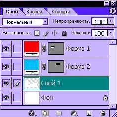
Figure 1 — Panel to work with layers in Adobe Photoshop.
Before we begin processing an image or a fragment thereof in PhotoShop, you must first make the selection for you part of it. To do this, there are different tools as simple selection of pixels, and more complex. By simple selection tools include:

Figure 2 — Panel of simple selection tool.
In addition to simple selection tools in PhotoShop and provides more sophisticated tools for selection.
Figure 3 shows the selection panel «Lasso» tool.

Figure 3 — Selection panel «Lasso» tool.
In addition to simple selection tools in Photoshop are also more complex, which perform a freehand selection.
An example of an instrument «Polygonal Lasso» is shown in Figure 4. Allocation indicated by the dashed line.
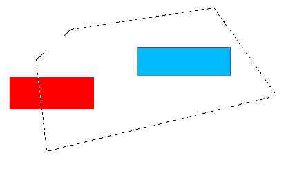
Figure 4 — An example of the tool «Polygonal Lasso».
Used for direct drawing tools with the «Brush» and «Pencil», which is essentially a special case of «Brushes».
«Brush» tool is designed to draw on the selection image with the mouse. Depending on the type of drawing pixels that are produced or another arithmetic — standard replacement of color, the choice of the dark or light, etc.
An example of the «Brush» is shown in Figure 5.
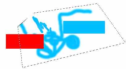
Figure 5 — An example of the «Brush» tool.
To work with the text provided as a simple text creation tools and tools create a mask from the text.
For printing an image provides the «Text» tool and an instrument of vertically oriented text.
«Text» tool is designed for the printing of any size and font to the image. The text is displayed in a rectangular selection, which can be stretched and rotated, and the text inside the selection is also rotated.
An example of applying a simple (left) and vertically oriented (right) of the text are shown in Figure 6.

Figure 6 — Properties panel, and an example of the «Text» tool.
The main orientation of the PhotoShop — hue image analysis, processing of whole groups of pixels, color and gamma correction, exposure to a variety of effects on selected parts of the image. To this end, the program includes a wide range of functions, adjustments and effects.
The first feature that allows to organize work with the image as a whole, is the ability to select the color model used when editing. The main color models are:
Suppose we are given the original image represented in Figure 7.
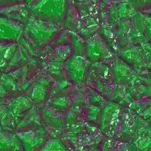
Figure 7 — Original image.
By the overall impact of the color components of image pixels, we can shift the hue of pixels in one direction or another. For example, in Figure 8 shows the original image pixels whose hue was shifted to red.
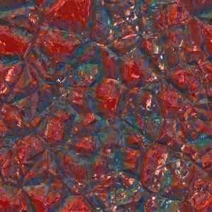
Figure 8 — Application of operation «Hue».
More subtle tool for influencing the image is a tool Levels. It is designed to adjust the pixel color according to their original color. Window with the «Levels» tool presented in Figure 9.
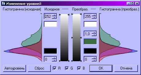
Figure 9 — Window with the «Levels» tool.
Arriving at the input pixels are called input and feedback — the output. Depending on the level of the input signal (ie the value of the color components of pixels) you can adjust the output level. Thus, the tool provides the ability to lighten too dark image areas and darken — light. The result of applying the tool can be seen in Figure 10.
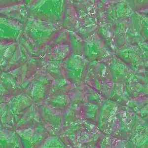
Figure 10 — The result of applying the «Levels» tool .
PhotoShop has a powerful selection tools processed the image. The program also included and drawing tools, but the possibility of changing the color and tone adjustments, and apply the effects much more than that recommended the product more as a means of processing of ready-made image, rather than as a program for direct imaging.
Vector model. Corel Draw
If, in a raster approach document is presented in the form of a set of pixels, the vector approach allows us to represent the scene as a set of objects described mathematically. It fills the stage sense, allows the artist to work on a new level — at the object level, filled with meaning and with specific properties, rather than a set of abstract pixels. This approach allows us to work with the scene as a set of interrelated elements, which greatly simplifies its understanding, accelerates to add new and modify existing items. Also, vector objects occupy much less disk space than bitmaps, as are stored as a set of mathematical formulas, rather than directly.
Corel Draw [3] is a vector graphics editor, which means the main focus of his tools and opportunities to work with the objects of the scene. For a simple select and view all the available facilities of the project has a special object manager, whose form is shown in Figure 11.
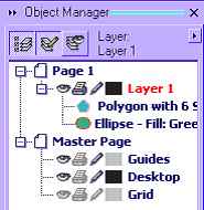
Figure 11 — Object Manager Corel Draw.
The image is divided into layers, each of the layers can include any number of objects. Each object has its own unique properties inherent in the objects of its type. In addition, objects can be complex and consist of a series of simpler objects. Each object can be used a set of effects that disrupt his appearance.
Each object typically has two main elements — shading and contour. For some types of objects of some of the elements may not be noticeable because of the singularities of the map object. Figure 12 shows an ellipse with a light gray fill and black outline.

Figure 12 — Ellipse with a light gray fill and black outline.
Since the Corel Draw graphics editor, focused on work with objects, it has many tools for their creation and transformation.
Select objects by a special Selection tool, which identifies the object, which was produced by a mouse click. Another way to select an object manager, mentioned above. It provides easy selection of objects, including parts of which are complex objects. Thanks to a brief summary of the properties and object name, you can easily find a desired object.
To create objects in Corel Draw provides several tools. Each tool is designed to create objects of its type.
Objects of different types have different properties, therefore, each tool for creating objects has its own settings and how to use.
The figure 13 shows a rectangle with round the corners — 50 degrees, as well as the properties panel «Rectangle» tool, which displays the properties of the selected rectangle.

Figure 13 — An object of class «Rectangle», and the properties panel «Rectangle» tool.
In addition to objects of class «Rectangle» Corel Draw lets you create and other objects. Their examples are shown in Figure 14.

Figure 14 — Objects of different classes created in the Corel Draw.
On a par with the tools to create objects using tools and applying various effects on them. These tools do not create new objects and for use require the already created objects. In applying the tool to an object, its properties, a list of modifiers and apply the effects. Effects serve to change the appearance of objects.
Figure 15 shows three objects.
The first (left) — a pentagon, the applied tool «Interactive extrusion», which allows you to create the illusion of three-dimensionality two-dimensional object by building its projections.
The second (top) — a pentagon, the applied tool «Interactive shadow». With this tool, you can create a drop shadow from the object.
The third object (below) — a rectangle, which used the tool «Interactive Path». This tool adds to the object of a specified number of units «outside» or «inside». Contours may be changing with every contour color, and size.
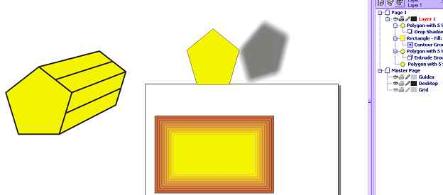
Figure 15 — Demonstration of instruments blending effects.
Corel Draw has a great fit for creating text with a variety of artwork. The program has two types of text: a simple and artistic.
Due to the vector approach, Corel Draw can work with text as an object — it makes it easy to change not only the appearance of the text but the text itself.
An example of a literary text with an application to the tools, «Interactive squeezing» is shown in Figure 16 (top). The same figure shows an example of plain text (below).
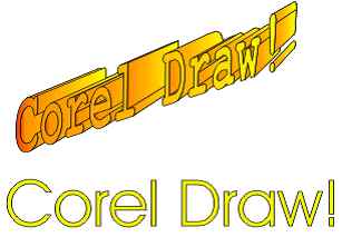
Figure 16 — An example of a literary text (above) and plain text (below).
Corel Draw — a vector graphics editor, designed to create collages, posters and billboards of various levels of complexity. For this purpose he has in his arsenal many powerful tools for creating objects of different types, and changing the appearance of these objects with different effects.
The final image is created by the layout of objects, so that Corel Draw has a convenient object manager, which allows for quick and easy access to each of them. The editor does not have instruments of direct changes raster images — it is formed from the vector objects as an end product of the program.
Comparison of editors and approaches
Thanks to the scanning direction, Photoshop has the ability to analyze and modify the properties of whole groups of pixels. This is the essence of tone and color correction — as a component of the selected pixels is changed simultaneously for all pixels, which creates the effect of lightening, darkening, manipulates the contrast or color range image. Corel Draw does not use the concept of the raster, which does not allow him to use in operations that affect the individual pixels of the image.
Such operations include direct and drawing on the image. In Photoshop, it is met through the establishment of separate groups of pixels and then applying them to the drawing tools — «Brush», «Pencil», «Fill». They come in very useful when you need manual correction of fine details. Corel Draw operates on the notion of «Fill», but in relation to objects, which imposes some restrictions on it.
At the same time, the vector is an undeniable plus compared to scanning — is the ability to scale without quality loss [4]. This is possible because the vector editor objects are stored in a mathematical form that allows you to build them as accurately as desired. Corel Draw — vector graphics editor, so the accuracy and clarity of display of objects depends only on the hardware capabilities. On the big screen object Corel Draw will look more clear than on the small, while the smaller images in Photoshop, extended to larger sizes will have a blurred outline.
If we talk about convenience selection, in Corel Draw is a problem virtually nonexistent. Thanks to the manager object to the item or part thereof, if he compound, just a click away. However, Corel Draw is not possible to allocate part of the whole object (for example, part of the circle). Each object may consist of several parts, but they can not be broken down to a level below the base object editor. Photoshop — bitmap editor and his paper is divided into pixels. Photoshop does not distinguish between objects in the image — for him all the pixels are identical and only one can discern objects in the image on the semantic meaning, as a rule, in stark contrast to the background color. Based on this, some selection tools Photoshop. Despite the fact that affectedly desired area of pixels is not so easy, Adobe has tried to simplify this task by introducing intelligent selection tools — Magnetic Lasso, Magic Wand. Moreover, if the selection is not complicated, it is possible to allocate more simple tools, by hand. However, in any case, it is not as easy as in Corel Draw.
Due to the fact that Corel Draw literary text — the same facility, like all others, you can apply the same effects, and convert that to the other objects. With this in Corel Draw you can create an entire patterned fonts. Yet it lacks the possibility of direct raster editing application for small details on the text to give a more natural look. Photoshop has scant opportunity to work with text. It allows the ability to draw a relatively simple design of the text to which no special tricks and artistic effects are not so easy to give an original colorful look.
Total
Both approaches to working with graphics have their advantages and disadvantages. Bitmap editor often lack the versatility and ease of use of a vector and a vector — attention to detail scanning. At the same time, neither one nor the other, not be sufficient to automate the creation of images. Many of the images would be easier to build the program by setting some known parameters and algorithms than to manually build the image. For example, the texture of rain may consist of droplets of different color, size, shape. To create this manually, the designer would have to manually have long objects in the image. Photoshop has a variety of patterned brush, but they do not give that freedom, which has, in fact, a program that generates image parameters.
In this regard, it would be logical to create an editor who would combine the main advantages of bitmap and vector approach to working with graphics [5].
In addition, packages of Adobe Photoshop and Corel Draw are the representatives of different forms of representation and processing of graphic information. At the time, like Adobe Photoshop is a bitmap editor and more focused on the processing of pixels, then Corel Draw — a vector graphics editor, which provides the possibility of forming an image with various objects.
Vector and bitmap graphics are fundamentally different forms of presentation graphics. In this regard, it is important to highlight the advantages and disadvantages of each of the forms to the possible merger of their strengths in one universal graphic editor.
Raster model. Adobe Photoshop
Raster approach to working with graphics-oriented processing of raster images or parts of it. In this case, the artist has the ability to directly affect the individual pixel of the image, alone or in groups. This gives the designer just two advantages. The first — an opportunity to influence the smallest image details, conducting a very precise correction of its individual parts. The second — an opportunity to influence the group of pixels at the same time, changing the general characteristics of the selected groups, such as color components, gamma, brightness. The disadvantage of this approach is the low level of abstraction — the designer is forced to work on the image at the level of individual pixels, which makes many operations for adding new and editing of finished parts of the image tedious and time consuming.
PhotoShop is a bitmap editor, focused primarily on digital photography, color correction of the entire image or its parts, tone correction, and analysis of color and tonal range of an image. He also has many tools for removing artifacts, correcting small details.
In addition to a variety of artistic techniques, which allows for PhotoShop, it has many built-in tools and effects. We consider them in more detail the example of the program PhotoShop 7.0 [2].
As already mentioned, most operations are not performed on an image as a whole and on its individual layers. The layers are created in various ways — direct creation of a new layer, new layer by copying an existing one, layer by inserting an image from a file, etc. The window to work with layers shown in Figure 1.

Figure 1 — Panel to work with layers in Adobe Photoshop.
Before we begin processing an image or a fragment thereof in PhotoShop, you must first make the selection for you part of it. To do this, there are different tools as simple selection of pixels, and more complex. By simple selection tools include:
- Rectangular selection;
- Ellipse selection;
- Single column;
- Single line.

Figure 2 — Panel of simple selection tool.
In addition to simple selection tools in PhotoShop and provides more sophisticated tools for selection.
Figure 3 shows the selection panel «Lasso» tool.

Figure 3 — Selection panel «Lasso» tool.
In addition to simple selection tools in Photoshop are also more complex, which perform a freehand selection.
An example of an instrument «Polygonal Lasso» is shown in Figure 4. Allocation indicated by the dashed line.

Figure 4 — An example of the tool «Polygonal Lasso».
Used for direct drawing tools with the «Brush» and «Pencil», which is essentially a special case of «Brushes».
«Brush» tool is designed to draw on the selection image with the mouse. Depending on the type of drawing pixels that are produced or another arithmetic — standard replacement of color, the choice of the dark or light, etc.
An example of the «Brush» is shown in Figure 5.

Figure 5 — An example of the «Brush» tool.
To work with the text provided as a simple text creation tools and tools create a mask from the text.
For printing an image provides the «Text» tool and an instrument of vertically oriented text.
«Text» tool is designed for the printing of any size and font to the image. The text is displayed in a rectangular selection, which can be stretched and rotated, and the text inside the selection is also rotated.
An example of applying a simple (left) and vertically oriented (right) of the text are shown in Figure 6.

Figure 6 — Properties panel, and an example of the «Text» tool.
The main orientation of the PhotoShop — hue image analysis, processing of whole groups of pixels, color and gamma correction, exposure to a variety of effects on selected parts of the image. To this end, the program includes a wide range of functions, adjustments and effects.
The first feature that allows to organize work with the image as a whole, is the ability to select the color model used when editing. The main color models are:
- RGB — Red Green Blue
- CMYK — Cyan Magenta Yellow blacK
- Lab
- Black-white
Suppose we are given the original image represented in Figure 7.

Figure 7 — Original image.
By the overall impact of the color components of image pixels, we can shift the hue of pixels in one direction or another. For example, in Figure 8 shows the original image pixels whose hue was shifted to red.

Figure 8 — Application of operation «Hue».
More subtle tool for influencing the image is a tool Levels. It is designed to adjust the pixel color according to their original color. Window with the «Levels» tool presented in Figure 9.

Figure 9 — Window with the «Levels» tool.
Arriving at the input pixels are called input and feedback — the output. Depending on the level of the input signal (ie the value of the color components of pixels) you can adjust the output level. Thus, the tool provides the ability to lighten too dark image areas and darken — light. The result of applying the tool can be seen in Figure 10.

Figure 10 — The result of applying the «Levels» tool .
PhotoShop has a powerful selection tools processed the image. The program also included and drawing tools, but the possibility of changing the color and tone adjustments, and apply the effects much more than that recommended the product more as a means of processing of ready-made image, rather than as a program for direct imaging.
Vector model. Corel Draw
If, in a raster approach document is presented in the form of a set of pixels, the vector approach allows us to represent the scene as a set of objects described mathematically. It fills the stage sense, allows the artist to work on a new level — at the object level, filled with meaning and with specific properties, rather than a set of abstract pixels. This approach allows us to work with the scene as a set of interrelated elements, which greatly simplifies its understanding, accelerates to add new and modify existing items. Also, vector objects occupy much less disk space than bitmaps, as are stored as a set of mathematical formulas, rather than directly.
Corel Draw [3] is a vector graphics editor, which means the main focus of his tools and opportunities to work with the objects of the scene. For a simple select and view all the available facilities of the project has a special object manager, whose form is shown in Figure 11.

Figure 11 — Object Manager Corel Draw.
The image is divided into layers, each of the layers can include any number of objects. Each object has its own unique properties inherent in the objects of its type. In addition, objects can be complex and consist of a series of simpler objects. Each object can be used a set of effects that disrupt his appearance.
Each object typically has two main elements — shading and contour. For some types of objects of some of the elements may not be noticeable because of the singularities of the map object. Figure 12 shows an ellipse with a light gray fill and black outline.

Figure 12 — Ellipse with a light gray fill and black outline.
Since the Corel Draw graphics editor, focused on work with objects, it has many tools for their creation and transformation.
Select objects by a special Selection tool, which identifies the object, which was produced by a mouse click. Another way to select an object manager, mentioned above. It provides easy selection of objects, including parts of which are complex objects. Thanks to a brief summary of the properties and object name, you can easily find a desired object.
To create objects in Corel Draw provides several tools. Each tool is designed to create objects of its type.
Objects of different types have different properties, therefore, each tool for creating objects has its own settings and how to use.
The figure 13 shows a rectangle with round the corners — 50 degrees, as well as the properties panel «Rectangle» tool, which displays the properties of the selected rectangle.

Figure 13 — An object of class «Rectangle», and the properties panel «Rectangle» tool.
In addition to objects of class «Rectangle» Corel Draw lets you create and other objects. Their examples are shown in Figure 14.

Figure 14 — Objects of different classes created in the Corel Draw.
On a par with the tools to create objects using tools and applying various effects on them. These tools do not create new objects and for use require the already created objects. In applying the tool to an object, its properties, a list of modifiers and apply the effects. Effects serve to change the appearance of objects.
Figure 15 shows three objects.
The first (left) — a pentagon, the applied tool «Interactive extrusion», which allows you to create the illusion of three-dimensionality two-dimensional object by building its projections.
The second (top) — a pentagon, the applied tool «Interactive shadow». With this tool, you can create a drop shadow from the object.
The third object (below) — a rectangle, which used the tool «Interactive Path». This tool adds to the object of a specified number of units «outside» or «inside». Contours may be changing with every contour color, and size.

Figure 15 — Demonstration of instruments blending effects.
Corel Draw has a great fit for creating text with a variety of artwork. The program has two types of text: a simple and artistic.
Due to the vector approach, Corel Draw can work with text as an object — it makes it easy to change not only the appearance of the text but the text itself.
An example of a literary text with an application to the tools, «Interactive squeezing» is shown in Figure 16 (top). The same figure shows an example of plain text (below).

Figure 16 — An example of a literary text (above) and plain text (below).
Corel Draw — a vector graphics editor, designed to create collages, posters and billboards of various levels of complexity. For this purpose he has in his arsenal many powerful tools for creating objects of different types, and changing the appearance of these objects with different effects.
The final image is created by the layout of objects, so that Corel Draw has a convenient object manager, which allows for quick and easy access to each of them. The editor does not have instruments of direct changes raster images — it is formed from the vector objects as an end product of the program.
Comparison of editors and approaches
Thanks to the scanning direction, Photoshop has the ability to analyze and modify the properties of whole groups of pixels. This is the essence of tone and color correction — as a component of the selected pixels is changed simultaneously for all pixels, which creates the effect of lightening, darkening, manipulates the contrast or color range image. Corel Draw does not use the concept of the raster, which does not allow him to use in operations that affect the individual pixels of the image.
Such operations include direct and drawing on the image. In Photoshop, it is met through the establishment of separate groups of pixels and then applying them to the drawing tools — «Brush», «Pencil», «Fill». They come in very useful when you need manual correction of fine details. Corel Draw operates on the notion of «Fill», but in relation to objects, which imposes some restrictions on it.
At the same time, the vector is an undeniable plus compared to scanning — is the ability to scale without quality loss [4]. This is possible because the vector editor objects are stored in a mathematical form that allows you to build them as accurately as desired. Corel Draw — vector graphics editor, so the accuracy and clarity of display of objects depends only on the hardware capabilities. On the big screen object Corel Draw will look more clear than on the small, while the smaller images in Photoshop, extended to larger sizes will have a blurred outline.
If we talk about convenience selection, in Corel Draw is a problem virtually nonexistent. Thanks to the manager object to the item or part thereof, if he compound, just a click away. However, Corel Draw is not possible to allocate part of the whole object (for example, part of the circle). Each object may consist of several parts, but they can not be broken down to a level below the base object editor. Photoshop — bitmap editor and his paper is divided into pixels. Photoshop does not distinguish between objects in the image — for him all the pixels are identical and only one can discern objects in the image on the semantic meaning, as a rule, in stark contrast to the background color. Based on this, some selection tools Photoshop. Despite the fact that affectedly desired area of pixels is not so easy, Adobe has tried to simplify this task by introducing intelligent selection tools — Magnetic Lasso, Magic Wand. Moreover, if the selection is not complicated, it is possible to allocate more simple tools, by hand. However, in any case, it is not as easy as in Corel Draw.
Due to the fact that Corel Draw literary text — the same facility, like all others, you can apply the same effects, and convert that to the other objects. With this in Corel Draw you can create an entire patterned fonts. Yet it lacks the possibility of direct raster editing application for small details on the text to give a more natural look. Photoshop has scant opportunity to work with text. It allows the ability to draw a relatively simple design of the text to which no special tricks and artistic effects are not so easy to give an original colorful look.
Total
Both approaches to working with graphics have their advantages and disadvantages. Bitmap editor often lack the versatility and ease of use of a vector and a vector — attention to detail scanning. At the same time, neither one nor the other, not be sufficient to automate the creation of images. Many of the images would be easier to build the program by setting some known parameters and algorithms than to manually build the image. For example, the texture of rain may consist of droplets of different color, size, shape. To create this manually, the designer would have to manually have long objects in the image. Photoshop has a variety of patterned brush, but they do not give that freedom, which has, in fact, a program that generates image parameters.
In this regard, it would be logical to create an editor who would combine the main advantages of bitmap and vector approach to working with graphics [5].
Are unions of bitmap and vector approach is that the vector objects, originally presented in the form of mathematical formulas, eventually to appear on the output device is still given to the bitmap view. In this connection, it can be argued that the raster image object is mathematically defined mapping of objects to a specific output device. Therefore, we can distinguish two parts in the device system — bitmap and vector.
Raster part
End device output images, most often, is the screen. In addition, while working on a document, you need to see progress, manage the contents of the document and layout objects. We can conclude that the main space of the document must be raster form. Within this space, and vector objects will be displayed.
Since the end product of the graphical editor, most often, is the image in one of the recognized formats (bmp, jpeg, etc.), then define a certain rectangular area of a particular finite size, consisting of pixels, which will be the domain of the output document. What is displayed in the output document will ultimately be stored in a graphic file. In this case, the size of the image will be equal to the size of the output document.
In the output region is supposed to be the final form of the scene, so access to direct its editorial will be closed — the output area is only for the output of intermediate and final graphics. Itself, this information is stored in layers. Each layer consists of its own scanning region whose size is the size of the output area, as well as a set of objects in this layer. Figure 17 demonstrated the layered model of document.
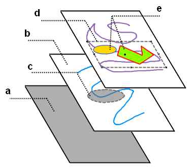
Figure 17 — Layered model of document.
Here :
This means that for the scanning area of each layer are available operations such as selection, direct drawing on the surface, color and tone correction. That is such a model fully implements all key features bitmap approach.
Vector part
In addition to scanning the field in each layer can also be a number of objects.
Objects have both common to all objects of the properties and the properties inherent in certain types of objects [6].
Common to all objects properties are:
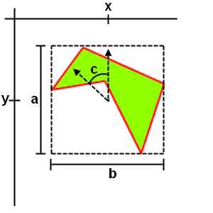
Figure 18 — Common object properties.
Here :
Objects can be nested. In a container object can be embedded several other objects which, in turn, may also be containers for other objects. It is necessary to enhance the convenience, logical grouping, as well as easier management of objects.
If the object is embedded, the interpretation of its general properties change. In this case, the position of the object is not specified in the space layer, and in the space of a container object. In other words, the coordinates of the center point is not defined under the left-upper edge of the raster layer, and from a central point container object. As the rotation - not in the global coordinate system, and in the CS of container object. Thus, if the container object is equal to the value of turning a, and embedded object: b, then in the global coordinate system, an embedded object will be turned at an angle a + b. However, bitmaps, embedded objects formed in accordance with the global position, to avoid unnecessary operations in the derivation of spatial objects on the screen.
Figure 19 illustrates how to interpret the general parameters of the objects, depending on the grouping.
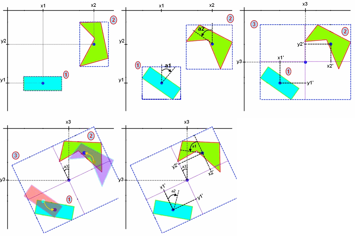
Figure 19 — Interpretation of the properties of objects, depending on the grouping.
We see two objects whose coordinates (x1, y1) and (x2, y2). Then, each object has been rotated around its center point at angles a1 and a2, respectively. The coordinates of the central points of the objects have not changed.
The third frame of the animation illustrates the grouping of these objects into one. At the same time the newly formed object has its own central point which has coordinates (x3, y3). You can also see that the coordinates of the original objects, (x1', y1') and (x2', y2') is now given by in the coordinate space of the newly created object with the center at its central point.
In the fourth frame of the animation produced container object is rotated around its center point at the corner of a3. In this case, we can see that in the space of a document position and rotation of objects 1 and 2 change. Thus, the angle of the first object becomes equal a1 + a3, the second: a2 + a3 [8].
At the same time, the position of objects inside a container object has remained unchanged, as seen in the fifth frame of animation.
Each object in the system has a path and, if the circuit is closed, the fill. The contour is described by mathematical equations, whose form depends on the type of object. This may be one or combination of functions of the form y = f (x). If the graphs of functions (the contour of the object) form a closed area, the object may have a fill. An example of an object from a closed loop is a rectangle, the object is not a closed loop — a line or curve does not intersect itself [9].
Fill objects can be of several types:
Dynamic scene generation
Using a raster-vector approach, of course, opens up opportunities for designers. Vector objects, you can easily manage the content of the scene, while the raster tools allow you to edit small details of objects, as well as to adapt the general mathematical model for a particular document.
However, the designer is still limited by a set of existing tools in the system. To create many simple at first glance, the effects, they often have to apply nedyuzhennuyu savvy to start using the tools available to achieve the desired result. In addition, although the use of groups and is a common technique in working with objects, direct relationship between them still is not created.
In this connection, the problem of strengthening the logical links between objects and the output document to a higher level of abstraction that would allow the designer to work less to individual objects, focusing on semantic filling stage.
To solve this problem will concept of data and commands, is widely used in programming. Its essence lies in the fact that the program (in our case — a method of constructing the stage) and data (in our case — the parameters of objects) are inseparable from each other and interchangeable. That is, the data for the program can be interpreted as commands, and commands — the data.
With regard to the graphical editor, this means that depending on the value of any document data, the construction stage will go one way or another. A simple example of this is svyazyvaenie two objects according to some principle. Such, in particular, is a figure — the equilateral triangle inscribed in a circle (Fig. 20). Here the size of the triangle is uniquely related to the size of the circle in which he entered. Of course, you can simply create two objects — a triangle and circle, group them and zoom in as one. However, this approach solves only a narrow range of tasks, they find themselves powerless in the case of more complex relationships between objects [10].
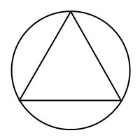
Figure 20 — Triangle inscribed in a circle.
Thus, we determined that the properties of objects (data) should be in some way linked. This connection can provide event model, also used in programming. Its essence lies in the fact that upon the occurrence of some event, the program must perform certain actions. The most common events in the graphic editor are events such as object creation, the formation of its bitmap (rendering), changing the dimensions and properties, relocation.
Based on the foregoing, we can formulate an algorithm that connects the circle and the inscribed triangle is this: when you change (the event), size (data), one of the figures, counted (the team) the size of the other [11].
To implement this behavior, each object has a set of standard events, each of which you can write a handler. Event handlers consist of a set of commands to be executed in case of a corresponding event. These commands can be:
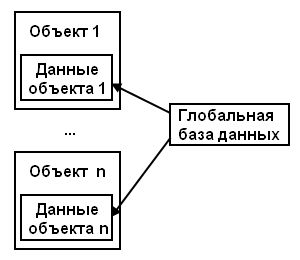
Figure 21 — The distribution of data in the system.
This approach enables situational form an image on the stage, forming its form depending on the available global data. In addition, it is often easier to describe the essence of the scene «in general», without going into detail, providing a concrete realization of the idea of the program. For example, to create a texture consisting of triangles of different color, size and position, the designer will have to manually copy a set of identical objects, and manually put them to the same property. Instead it is more convenient to simply specify a global database of created triangles, spread their characteristics, and write the corresponding handler, which is the formation of the document would create a specified number of triangles in the scene.
To store data on the developed stage, provides a graphical editor to save files in special format that would allow us to return to work over the stage without any loss of working data. This file format is a scene beyond the standard format for storing images (such as bmp, jpeg ...) because it keeps in itself is not finite two-dimensional map of the scene, and all the layers of objects and data from which the scene consists of. The contents of this file format might be:
Raster part
End device output images, most often, is the screen. In addition, while working on a document, you need to see progress, manage the contents of the document and layout objects. We can conclude that the main space of the document must be raster form. Within this space, and vector objects will be displayed.
Since the end product of the graphical editor, most often, is the image in one of the recognized formats (bmp, jpeg, etc.), then define a certain rectangular area of a particular finite size, consisting of pixels, which will be the domain of the output document. What is displayed in the output document will ultimately be stored in a graphic file. In this case, the size of the image will be equal to the size of the output document.
In the output region is supposed to be the final form of the scene, so access to direct its editorial will be closed — the output area is only for the output of intermediate and final graphics. Itself, this information is stored in layers. Each layer consists of its own scanning region whose size is the size of the output area, as well as a set of objects in this layer. Figure 17 demonstrated the layered model of document.

Figure 17 — Layered model of document.
Here :
- a. — output region of the document.
- b. — bitmap space layer.
- c. — dedicated to the domain layer.
- d. — selected an object.
- e. — objects of the composite object.
This means that for the scanning area of each layer are available operations such as selection, direct drawing on the surface, color and tone correction. That is such a model fully implements all key features bitmap approach.
Vector part
In addition to scanning the field in each layer can also be a number of objects.
Objects have both common to all objects of the properties and the properties inherent in certain types of objects [6].
Common to all objects properties are:
- Size — height (distance in pixels from the top pixel of the object to the bottom) and width (the distance from the leftmost pixel of the object to the far right)
- Position — the coordinates of the center point of the object
- Turn — the angle of rotation of the object around its center point
- Bitmap — the final image of the object that is displayed in the raster domain layer

Figure 18 — Common object properties.
Here :
- a — object's height in pixels
- b — object's width in pixels
- x,y — coordinates of the center of the object from the left-upper edge of the raster area
- c — rotation angle around its center point
- Bitmap — it's actually kind of rotated around its central point of the object
Objects can be nested. In a container object can be embedded several other objects which, in turn, may also be containers for other objects. It is necessary to enhance the convenience, logical grouping, as well as easier management of objects.
If the object is embedded, the interpretation of its general properties change. In this case, the position of the object is not specified in the space layer, and in the space of a container object. In other words, the coordinates of the center point is not defined under the left-upper edge of the raster layer, and from a central point container object. As the rotation - not in the global coordinate system, and in the CS of container object. Thus, if the container object is equal to the value of turning a, and embedded object: b, then in the global coordinate system, an embedded object will be turned at an angle a + b. However, bitmaps, embedded objects formed in accordance with the global position, to avoid unnecessary operations in the derivation of spatial objects on the screen.
Figure 19 illustrates how to interpret the general parameters of the objects, depending on the grouping.

Figure 19 — Interpretation of the properties of objects, depending on the grouping.
We see two objects whose coordinates (x1, y1) and (x2, y2). Then, each object has been rotated around its center point at angles a1 and a2, respectively. The coordinates of the central points of the objects have not changed.
The third frame of the animation illustrates the grouping of these objects into one. At the same time the newly formed object has its own central point which has coordinates (x3, y3). You can also see that the coordinates of the original objects, (x1', y1') and (x2', y2') is now given by in the coordinate space of the newly created object with the center at its central point.
In the fourth frame of the animation produced container object is rotated around its center point at the corner of a3. In this case, we can see that in the space of a document position and rotation of objects 1 and 2 change. Thus, the angle of the first object becomes equal a1 + a3, the second: a2 + a3 [8].
At the same time, the position of objects inside a container object has remained unchanged, as seen in the fifth frame of animation.
Each object in the system has a path and, if the circuit is closed, the fill. The contour is described by mathematical equations, whose form depends on the type of object. This may be one or combination of functions of the form y = f (x). If the graphs of functions (the contour of the object) form a closed area, the object may have a fill. An example of an object from a closed loop is a rectangle, the object is not a closed loop — a line or curve does not intersect itself [9].
Fill objects can be of several types:
- Solid — closed area of an object filled with one color.
- Mask — casting an object is given a special mask. Mask — a rectangular matrix describing for each pixel, then, in what proportions to mix the color mask. An example mask is a two-color gradient fills — in such a filling each pixel is a combination of the two main color of the mask. Then, in what proportions they will be mixed, and determines the color of a pixel. Mask — raster object and has its own resolution. The higher the resolution (dimensions) mask, the more accurately it describes the object's fill, which is applied. When you apply the mask to the object, it is scaled to the size of the object itself — compressed or stretched.
- Image — as a fill using the final image. Feature of this type of casting is the ability to directly edit it, as if the object is a separate layer. This opens up wide possibilities for changing the appearance of objects — from a variety of shape and form of filters to the exact correction of the appearance of objects.
Dynamic scene generation
Using a raster-vector approach, of course, opens up opportunities for designers. Vector objects, you can easily manage the content of the scene, while the raster tools allow you to edit small details of objects, as well as to adapt the general mathematical model for a particular document.
However, the designer is still limited by a set of existing tools in the system. To create many simple at first glance, the effects, they often have to apply nedyuzhennuyu savvy to start using the tools available to achieve the desired result. In addition, although the use of groups and is a common technique in working with objects, direct relationship between them still is not created.
In this connection, the problem of strengthening the logical links between objects and the output document to a higher level of abstraction that would allow the designer to work less to individual objects, focusing on semantic filling stage.
To solve this problem will concept of data and commands, is widely used in programming. Its essence lies in the fact that the program (in our case — a method of constructing the stage) and data (in our case — the parameters of objects) are inseparable from each other and interchangeable. That is, the data for the program can be interpreted as commands, and commands — the data.
With regard to the graphical editor, this means that depending on the value of any document data, the construction stage will go one way or another. A simple example of this is svyazyvaenie two objects according to some principle. Such, in particular, is a figure — the equilateral triangle inscribed in a circle (Fig. 20). Here the size of the triangle is uniquely related to the size of the circle in which he entered. Of course, you can simply create two objects — a triangle and circle, group them and zoom in as one. However, this approach solves only a narrow range of tasks, they find themselves powerless in the case of more complex relationships between objects [10].

Figure 20 — Triangle inscribed in a circle.
Thus, we determined that the properties of objects (data) should be in some way linked. This connection can provide event model, also used in programming. Its essence lies in the fact that upon the occurrence of some event, the program must perform certain actions. The most common events in the graphic editor are events such as object creation, the formation of its bitmap (rendering), changing the dimensions and properties, relocation.
Based on the foregoing, we can formulate an algorithm that connects the circle and the inscribed triangle is this: when you change (the event), size (data), one of the figures, counted (the team) the size of the other [11].
To implement this behavior, each object has a set of standard events, each of which you can write a handler. Event handlers consist of a set of commands to be executed in case of a corresponding event. These commands can be:
- Receiving data — getting the value of some parameter of a particular object or from another source.
- Getting random number.
- Change Data — change the inherent properties of the object based on the data obtained. These properties can be color, position, size and other properties.
- Initiating event — call the standard function that handles the event, as well as a custom handler.
- Download a mask, the texture data from an external file.
- And others ...

Figure 21 — The distribution of data in the system.
This approach enables situational form an image on the stage, forming its form depending on the available global data. In addition, it is often easier to describe the essence of the scene «in general», without going into detail, providing a concrete realization of the idea of the program. For example, to create a texture consisting of triangles of different color, size and position, the designer will have to manually copy a set of identical objects, and manually put them to the same property. Instead it is more convenient to simply specify a global database of created triangles, spread their characteristics, and write the corresponding handler, which is the formation of the document would create a specified number of triangles in the scene.
To store data on the developed stage, provides a graphical editor to save files in special format that would allow us to return to work over the stage without any loss of working data. This file format is a scene beyond the standard format for storing images (such as bmp, jpeg ...) because it keeps in itself is not finite two-dimensional map of the scene, and all the layers of objects and data from which the scene consists of. The contents of this file format might be:
- Global Database — includes data that are common to many objects, or characteristic of the entire document.
- Global handlers — contains the event handlers, on the whole document (create a scene, for example).
- Other data scene — contains data used by the scene objects by default (out of handlers) — masks, palette of colors, shading, etc.
- Layers — information about each and layers. Includes:
- Scanning area — raster layer region.
- Objects — information about objects contained in this layer. Includes:
- Type — the type of object.
- Properties — the general properties of the object (position, rotation, color, shading) and the inherent properties of a particular type of object (the radius for the circle).
- Data — abstract data used in the handlers.
- Handlers — the event handlers of the object.
- Sub-objects — if the object — the container, it also contains information about embedded objects.
Developed a graphical editor is an attempt to combine the two basic approaches to work with graphics - vector and raster. At that time, both raster approach has a low level of abstraction and allows image processing at the level of individual pixels, thus giving the opportunity to produce a very accurate image correction vector approach provides a high level tools for creating and processing of graphic objects, largely automating the process of creating and Processing of graphical information [12].
Despite all the advantages of each approach, the solution of many problems rendering is very time-consuming process, requiring designers to nedyuzhennoy intelligence. To simplify the process of forming images, as well as provide a deeper logical relationship between objects in a graphics editor will use the concept of commands and data, which is using the event model will link together all the scene objects, and to some extent programmed process of generating images. For the convenience of storing all the information about the developed stage will be developed in a file format that would include the data about the objects and layers, scenes, and related data, along with event handlers that these data are used.
In the future we plan to develop a special player file format photo editor that would allow you to view files scenes, generating them based event model and data concepts. This will allow to enter into use a new type of graphical information - images generated depending on external factors. Also in the event-driven model of the document can enter the event, which would react to user actions - mouse moves, keystrokes and mouse clicks. This will create a truly interactive documents and forged to user interaction.
Another possible through the development of the system is writing a series of special libraries [13], which would provide the programmer the tools to generate graphical user interfaces of different profiles. Thus, it would seem possible by using a graphical editor to create special files, scenes, and then connect them to the program developed by the programmer. In this case, the programmer would be freed from having to follow the subtleties of the programming interface as the decommissioning and conversion charts would carry out the library, taking as input a file that you downloaded the scene, and the programmer would have remained only generate events for its graphics engine.
Summarizing, we can say that this work holds great promise in practical applications and is an important development in this direction. However, at the time of this writing, the site development work is not completed yet. Complete results of the development can be obtained from the authors after January 2012.
- Магдалина С.Н., Карабчевский В.В. Визуальное создание двумерных текстур средствами DirectX 9.0C // Комп'ютерний моніторинг та інформаційні технології — Матеріали V науково-технічної конференції студентів, аспірантів та молодих науковців. — Донецьк : ДонНТУ — 2009. — 368 с.: іл.
- Александр Тайц, Александра Тайц. Самоучитель Adobe Photoshop 7. — СПб.: БХВ-Петербург, 2005. — 688 с.: ил.
- Миронов Д. Corel Draw 11. Учебный курс. СПб.: Питер, 2002. — 448 с.: ил.
- Магдалина С.Н., Карабчевский В.В. Создание графического редактора для обработки текстур средствами DirectX 9.0C — Матеріали третьої міжнародної науково-технічної конференції "Моделювання та компьютерна графіка". — Донецьк : ДонНТУ — 2009.
- Магдалина С.Н., Карабчевский В.В. Визуальное создание двумерных текстур средствами DirectX 9.0c — Наукові праці Донецького національного технічного університету. Серія "Інформатика, кібернетика і обчислювальна техніка" (ІКОТ-2009). Випуск 10(153) — Донецьк : ДонНТУ. — 2009. — 368с.
- Магдалина С.Н., Карабчевский В.В. Визуальное создание изображений средствами Direct2D с использованием растрово-векторного подхода
- Станислав Горнаков. DirectX 9: Уроки программирования на С++. СПб.: БХВ — Петербург, 2005. — 400 с.: ил.
- Михаил Фленов. DirectX и С++. Искусство программирования. СПб.: БХВ — Петербург, 2006. — 384 с.: ил.
- Френк Д. Луна. Введение в программирование трехмерных игр с DirectX 9.0. Wordware Publishing, 2006. — 424 с.: ил.
- Тодд Бэррон. Программирование стратегических игр с DirectX 9.0. Wordware Publishing, 2003. — 700 с.: ил.
- Том Миллер. Managed DirectX 9.0 с управляемым кодом. Программирование графики и игр. SAMS, 2003. — 432 с.: ил.
- Документация по DirectX Direct2D [Электронный ресурс] / Интернет-ресурс. — Режим доступа: www/ URL: http://msdn.microsoft.com.
- Секунов Н.Ю. Самоучитель Visual C++. СПб.: БХВ-Петербург, 2002. — 250 с.: ил.