
Abstract
Development and research institutions transmission unit
Data based on HDL and FPGA technologies
Contents
Introduction
Recently, the trend for global monitoring - structured monitoring systems. In this case, the system organized several remote observations, which are located at different levels and perform different tasks. Both panels the lower level (usually in the city) undertaking operational tasks - gathering information on objects and provide prompt response to alarm events. Further, they convey information about events and actions of the staff at the remote central monitoring stations (CMS) - district, regional, territorial or national scale. CMS does not perform operational tasks, and serve to control the action jurisdictional staff, collecting data for statistics and further analysis. The positive experience of creating such systems already exist. On the basis of such systems, it is easy to organize a rescue of type 911. One of the most important components of such monitoring systems is the radios transmit and receive information. Their portability, immunity, and price - these are the parameters by which they are elected. Using digital coding techniques provide more information capacity of a system that allows use of a transmitting device in the composition from object systems, large capacity, for example, targeted devices with a large number of controlled areas. In the master's work done development and research of data transmission systems, which will take the form of portable devices, made with the use of HDL-and FPGA-technology. Will be developed FPGA-device on a chip family from Altera's Cyclone and IP-core error detection and correction based on Reed-Solomon codes, which will improve the noise immunity of the device. With the help of the experimental complex structure will be studied data transmission system that is proposed.
Topicality
The urgency of those master's thesis is that, firstly, as shown in the introduction, the device data are widely, we can say widespread use, and secondly, the function of providing immunity, is an integral part of these systems, and, Third, existing data should be improved techno-economic indicators. The topic of this master's work, aimed at the development and study of the structure of the data is relevant.
Aims and objectives
The purpose of master's work is the development and study of the structure of the data with the function of noise immunity, superior counterparts on technical and economic indicators. To achieve this objective in the following tasks:
- Development of FPGA-structure data transmission system with the function of immunity based on Reed-Solomon codes;
- Development and Pilot handheld device data transmission over the air on the basis of HDL-and FPGA-design technologies;
- Investigation of the proposed structure of data transmission through testing and analysis of the experimental device developed by techno-economic indicators.
Scientific significance
Scientific novelty of the work lies in the fact that it is supposed to develop a new structure of noise-data based on Reed-Solomon codes, providing higher technical and economic performance compared with counterparts due to the use of modern FPGA-design technologies.
The practical value
Based on the proposed structure will be developed in an experimental portable data transmission over the air on the basis of HDL-and FPGA-design technologies. The base is supposed to use FPGA ASIC family firm ALTERA Cyclone. As a description languages and programming the equipment selected VHDL and C / C + +. To ensure the functions of immunity will be developed two IP-core implementing the encoder and decoder of Reed-Solomon. Debugging of the digital part of the project will be executed on the basis of the debugging complex «Altera Nios II Embedded Evalution Kit» (NEEK).
The practical significance of this work is that on the basis of the proposed structure can be developed for effective technical and economic indicators specific device data-oriented use of the FPGA.
Description of studies
Figure 1 shows a generalized scheme of interaction between the transmitter and receiver that communicate
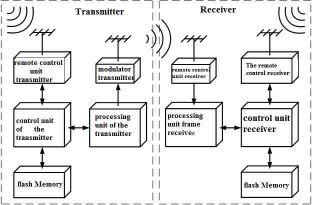
Pic.1 generalized scheme of interaction between the transmitter and receiver
The work of the transmitter is that for a particular signal that arrives from the remote control receiver (BDKPR) receiver control unit (BKPR), which is based on a microcontroller (MC), loads the firmware from the memory block of the transmitter (BPPD) in a chip from the company Altera. As loaded, the firmware may be either for a specific FPGA or data frames, which were previously recorded in BPPD. Once the firmware has been successfully loaded into the FPGA, the processing unit frame transmitter (BOKPD) may make acceptance, processing and delivery of data frames.
Over each frame, which was received, BOKPD performs the following operations:
- checksum frames;
- Coding frame and the checksum computed error-correcting code;
- Bitwise scrambling and frame the issue at a frequency of 8 MHz.
Frame, which is given bitwise with BOKPD, the input of the modulator (MD), which converts each bit of data to the appropriate radio signal. The receiver is that for a particular signal that arrives from the remote control receiver (BDKPR), the control unit receiver (BKPR) loads the firmware from the memory block receiver (BPPR) a processing unit frame receiver (BOKPR). Once the firmware has been successfully loaded into the FPGA BOKPR, this unit can perform acceptance, processing and delivery of data frames. Each frame is accepted as an appropriate signal demodulator (DM) and turns them into a sequence of bits which is fed to the input BOKPR. BOKPR, in turn, carries over each frame of data supplied, the following:
- Bitwise deskrembirovanie frame;
- Decode the frame and received checksum error-correcting code decoder;
- Counting and checksum frame with appropriate sign.
After the next frame of user data was received, checks the sign BKPR correct its checksum. If the frame was received without errors, then overwrites it with BKPR BOKPR in BPPR. Otherwise the received frame is discarded. Given the fact that the errors in the channel have a batch in nature, using the code that corrects packet errors makes no sense to perform the mixing matrix of information in order to avoid dispersion of packet errors on a number of separate, greatly complicate their correction.
Once the function and place of the FCS in the transmitter and receiver have been identified, it is necessary to elaborate on the structure of these blocks. Fig. 2 shows a generalized scheme of CCK transmitter and receiver. At this key components of both CCK is not dependent on the specific code cyclic error-correcting code and control, as well as the direction of information transfer in the interaction between individual components of a and blocks as a whole. The structure of the transmitter includes the following main components:
- Transmitter FIFO - serves to buffer the frames destined for dispatch;
- The calculation scheme package cycle control (SRKTSK) - analyzing the input data stream, calculates the checksum for the frame with a single of standard algorithms;
- Switch the input to the encoder error-correcting code (S1) - used for switching the input to the encoder error-correcting code data block directly or calculated checksum value frame;
- Coder error-correcting code (CPC) - performs noise-stable coding input data and issue the check information;
- The output of the transmitter switch (S2) - used to switch to one input of the output adder modulo "2" data frame, the frame checksum or verifying information received after the error-correcting coding;
- Scrambler - performs the generation of pseudo-random sequence, arriving at the second input of adder modulo "2" in order to eliminate long sequences ones and zeros;
- Managing automatic transmitter (SC AP) - controls the operation of all other circuit components of the transmitter, the recipient of information signals and produces control.
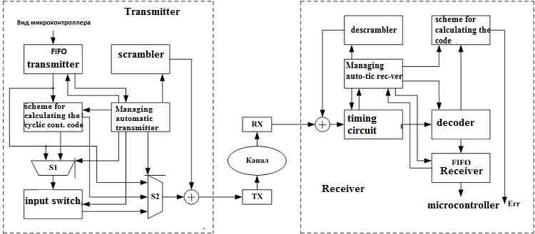
Pic.2 A generalized scheme of processing units training the transmitter and receiver
Operation of the transmitter, which was built under the scheme is as follows. First, to initialize all listed components of the transmitter. After recording, the FIFO of the transmitter of the next frame, the frame is transmitted to the output Switch S2, where the sum modulo "2" with the value at the output of the scrambler and the input of the modulator. In parallel with the issuance of the line also runs the checksum frame and pass it through a switch S1 to the input of the encoder error-correcting code. As soon as the error-correcting code encoder processes the data block of a certain length, it throws him through the switch S2, and terminates at the time of issuance of the check directly to the publication of data and calculation of the checksum. Immediately following the issuance of the check information is restored through the transfer switch S2 data frame Checksum calculation and re-start encoding the next block of data. After the transfer of full frame data through switch S2 to the end line and formed a frame checksum, it goes through the switch S1 to the input of the encoder error-correcting code, and simultaneously through the switch S2 to the line, thereby complementing the data frame, which was published earlier. Upon completion of the issuance checksum simultaneous completion of the last block of data encoding part of the frame and verification information is returned via the switch S2 to the line, thus completing the transfer of the frame. The last step of the process frame transmission is re-initialize all the components of the transmitter, and the transition to the next frame waiting for sent. Managing automatic transmitter full control over the work of all its components are listed to give up some of these data signals, determining their status, and issuing the necessary control signals for each of these components. The composition the receiver includes the following main components:
- Descrambler - performs the generation of pseudo-random sequence, arriving at one input of an adder modulo "2" to restore the original data stream to the other input of the adder is fed a data stream coming from the demodulator;
- Scheme code review cycle control (SPKTSK) - analyzing the input data stream, checks the value of the control amounts to the frame using one of the standard algorithms;
- Decoder error-correcting code (DKPK) - performs noise-immune decode input data and error correction, arising from the use of screening information;
- Transmitter FIFO - serves to buffer frames destined for dispatch;
- Managing automatic transmitter (SC AP) - controls the operation of all other components of the transmitter circuit, getting them data signals and passing control.
Operation of the receiver, which is built on such a scheme is as follows. First, to initialize all listed components the receiver. The input data stream coming from the demodulator, which consists of module "2" to the output stream descrambler, so there is a restoration of the original sequence that is encoded data frame. Deskremblovany initial bit stream to the input of block allocation and timing data, where it is split on the line synchronization, which is applied to all internal components of the receiver, and the data line is the information part of the frame. Divided flow the input of the decoder error-correcting code, which performs decoding of each data block of a certain length inside the full frame of data, and by the presence of a number of abnormal screening information corrects the errors that might occur in during transmission of each block via radio. The output of the decoder information goes parallel to the FIFO and the receiver to the input of the system code review cycle control, which generates a new checksum for the frame. According to the analysis the current checksum frame, schema validation can set up an appropriate sign of error. Depending on the value of the current signs of error recorded in the FIFO or receiver frame is read by the microcontroller in the command block memory of the receiver, or ignored, is removed from the FIFO without burning somewhere. The last step in the process of reception of the next frame, as in the case of the transmitter is re- initialize the receiver and its components in the transition state to await receipt of the next frame of data. Managing automatic receiver complete control over the work of all its components are listed to give some of them the information signals that determine their state, and issuing the necessary control signals for each of these components.
Select a code for cyclic control. The most popular algorithms today checksum of a block or data is CRC16 and CRC32. The range of application of these algorithms is very wide, and their software implementations used to compute checksums of files, or any other data sets in various formats, and hardware - to calculate checksums or other personnel units of information in the networking and communications devices. Such popularity is due to the CRC calculation algorithms in that they allow with very high probability to determine the damage in the transfer of information on the "plague-stricken," the communication channels or defects medium in which it was stored.
CRC16 and CRC32 algorithms form the basis for some of the incoming message on 16-bit or 32-bit sequence bits, which are usually attached to the message and then used to test for bugs in it after transmission or storage.
In this work, to ensure the integrity of the frame during transmission over the air, was chosen algorithm CRC32. The choice was made because that it may be more likely to detect errors in the transmission frame over CRC16.Shemno CRC32 algorithm is implemented in the form of a linear recurrent register (shift register with linear feedback.) Polynomial used for this algorithm is as follows:

Literature :
- 1. Kuzmin, VP, Kedrus VA Fundamentals of information theory and coding. - K.: Highest shk. Head House, 1986. - 238s.
- Tsymbal, VP, Information Theory and Coding: A Textbook. - K.: Highest Shkola, 1992.-263 with.: Il.
- WW Peterson, Weldon, E. Error-correcting codes. - M.: Mir, 1976. - 595s.: Il.
- Blahut, Theory and Practice of Error Control Codes: Trans. from English. - Moscow: Mir, 1986. - 576.: Il. .
- Ognev IV, Sarychev KF reliability of memory devices. - M.: Radio and Communications, 1988. - 224.
- Shuvalov, VP, Zakharchenko NV, Shvartsman, VO and other transmission of discrete messages. - M.: Radio and Communications, 1990. - 439s.
- Wikipedia [electronic resource] - Access mode to the electron source: http://ru.wikipedia.org
- Wikipedia [электронный ресурс] - Режим доступа к электронного источника: http://ru.wikipedia.org
- Methodical instructions to carry out laboratory work on the course "Information Theory and Coding." The "error-correcting coding (for students majoring 6.0915) / Glass: A. Dyachenko. -Donetsk: Donetsk State Technical University, 1998. - (An electronic copy number 2603).
- Methodical instructions to carry out laboratory work on the course "Information Theory and Coding" (for students majoring in 7.091501) / Glass: A. Dyachenko. -Donetsk: Donetsk National Technical University, 2005. - (An electronic copy).
- Methodological guidelines for independent work of students and to implement control tasks on the course "Applied theory of digital machines' content module" Coding Information "(PF.D.08.PR.O.01, PF.D.08.PR.O.02) blocks of content modules "Information Theory" (PN.18) "Coding Theory" (PN.19) (for students majoring 7.091501, 7.091502) / Glass: A. Dyachenko. - Donetsk: Donetsk National Technical University, 2005. - 34C (electronic medium).
- . Methodical instructions to carry out laboratory work on the course "Information Theory and Coding" (for students majoring 7.091501, 7.091502) / Comp.: AN Dyachenko, Yu.E.Zinchenko.-Donetsk: Donetsk National Technical University, 2006. - (An electronic copy number 5117).
- . Methodical instructions to carry out laboratory work on the course "Theory of error-correcting coding" / (for students majoring 7.091501, 7.091502) / Glass.: O.M.Dyachenko.-Donetsk: Donetsk National Technical University, 2007. - HTML-format (electronic format, number 18, Fr. № 7 of 06.20.2007)