
Abstract
Contents Introduction
- Introduction
- 1. Urgency of the subject and stating the problems
- 2. Review of the studies and developments on subject
- 3. Modeling of the instrument
- 4. Determination elementary forming power of the cutting
- 5. Analysis tense-deformed conditions to designs assembly have checked
- Conclusions
- List of the sources
Introduction
Since each year all more hard become the requirements to design material, from which are made responsible details and nodes, gravely loaded elements. One of the ways of the improvement characteristic metal is their corresponding to termal processing. As a result get the givenned field-performance datas of the details, but this brings about complication of their processing. For instance, railway rails subject to the three-dementional toughen in consequence of which processing hole in rail under fixing elements possible only hard alloy by instrument.
1. Urgency of the subject and stating the problems
At present for лезвийной of the processing hole in rail use assembly checked against mechanical fastening removable not sharpening plates. Is it In practice installed comparatively low stability given instrument. The Main reason of the loss to capacity to work is fallout cutting edges and it be split off tops. The Typical types of the wear-out removable not sharpening plates are brought on fig. 1

Figure 1. Typical type of the wear-out removable plates
Peripheral and central plate work in miscellaneous condition so nature of the wear-out in they differ. A wear-out is For peripheral plate typical devil on back surface and it be split off tops of the plate, which is found on maximum diameter (fig. 1). For central plate, located axis have checked, typical is area of the cutting edge, which is located closer to axis has checked (fig. 1).
The reason to low capacity to work assembly hard become has checked are considered heavy conditions of the cutting, caused particularity of the process of the drilling velocity of the cutting near axis of the instrument equal zero, and changing geometry and as effect - variable forming power of the cutting along cutting edges central and peripheral plates. One of the ways of increasing to capacity to work assembly have checked is a making the instrument with rational constructive and geometric parameter, which provide more even loading the cutting edges and minimization unbalanced radial forming power of the cutting, which appears during drilling.
2. Review of the studies and developments on subject
In [2] is described methods of the determination of the amplitude of the fluctuation when processing metal by cutting. The Process of the cutting often is accompanied the fluctuations with relatively small amplitude, the known under name of the vibrations. The fluctuations, on the one hand, negativly tell on work tool, accuracy and quality of the processed product, on the other hand, can render the positive influence, under vibratory processing for instance.
In this connection the primary tasks speakers process of the cutting are:
- Study of the reasons of the origin and developments of the fluctuations;
- The study to stability of the system and prospecting the efficient methods of the eliminating the fluctuations;
- The determination rational mode vibratory processing.
Differential equations are formed For description of the compelled system fluctuations tool. The Methods of the writing the differential equations of the compelled system fluctuations tool is considered in [2]:
In process of the cutting appearance external periodic power can be conditioned following reason:
- Work much blades instrument;
- Presence uneven cut layer;
- The Possibility of the forming the element shaving.
The Last more significant in the field of small importances of the velocities of the cutting, when frequency of the formation element comparable with own system frequency. Besides, compelled fluctuations can appear in system from drive tool, unbalanced revolving masses. Influence of the conditions of the processing on steady-state and dynamic components of power of the cutting are considered in [3]
Together with that, ambiguous literary given about composition of the spectrum of power of the cutting under milling cutter, as follows: in one source becomes firmly established that dynamic forming power of the cutting varies through frequency fz passings teeth through zone of the cutting, but in others that fluctuations of power of the cutting occur on frequency of the rotation of the milling cutter f0 and frequency fz.
Need of the study of the nature of the change of power of the cutting appears In this connection under planes by milling cutter and determinations of the dominant frequency of its change. Except this known mathematical model main forming power of the cutting under milling cutter, however empirical model dynamic forming power of the cutting is absent. The Called on studies have shown that because of influence of radial beating the milling cutter spectrum power of the cutting moves from frequency fz passings teeth through zone of the cutting to frequency of the rotation of the spindel. This can render the bad influence upon process of the cutting since dominant more low frequency of the harmonica become in spectrum of power of the cutting.
Besides, is installed that at presence of beating the milling cutter difference in powers of the harmonicas on circulating and tine frequency is found in back proportional dependency from value of the minute presenting. With reduction of the presenting influence beating milling cutters reveals itself on shift of the frequencies. Consequently, at presence forming power of the cutting will render else greater influence upon quality of the final processing.
Knowing frequency composition of the spectrum of power of the cutting and nature of its change under planes by milling cutter, possible go to determination of the law of the change dynamic forming power of the cutting. In [3] is brought methods of the development empirical model dynamic forming power of the cutting.
3. Modeling of the instrument
In step of designing the cutting instrument possible predict what image will affect constructive and geometric parameters on tense-deformed condition worker part assembly has checked against help of the numerical modeling and applied programs on their base. For the reason analysis of the influence constructive and geometric parameter worker part assembly has checked on her tense-deformed condition, us was created three-dimensional geometric model (fig. 2) and is organized her sampling (fig. 3).
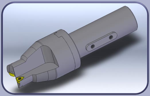
Figure 2. Model assembly has checked
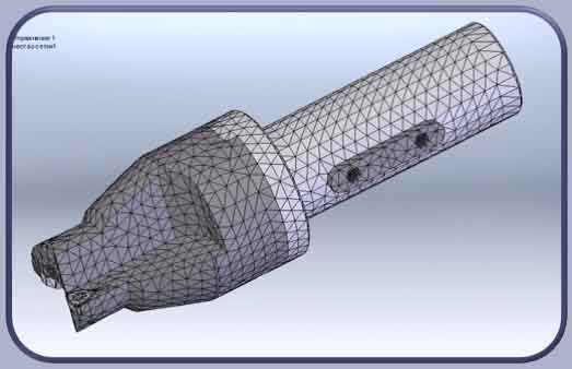
Figure 3. Sampling to models
Modeling was conducted for conditions of the processing by drill with standard constructive and geometric parameter on central and peripheral plate. The Initial conditions of the calculation corresponded to the steady-state analysis to assembly design with provision for factor of friction between element has checked and their relative kinematics.
Kinematicheskie border conditions imitated fastening tail checked in mandrel (fig. 4), but load corresponded to power of the fastening element checked and distribution forming power of the cutting along cutting edges of the plates in accordance with geometry (fig. 5).
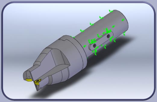
Figure 4. Kinematicheskie border conditions to models
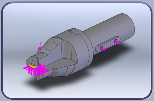
Figure 5. Load to models
For this were analysed geometric parameters have checked along cutting edges and loads, appearing on cutting edge each removable plates in process of the cutting.
4. Determination elementary forming power of the cutting
On base of the available accounting scheme (fig. 6) and analytical studies [1] are determined elementary forming power of the cutting, acting in separate point of the cutting edges instrument, which have a following type:
- elementary tangential forming:
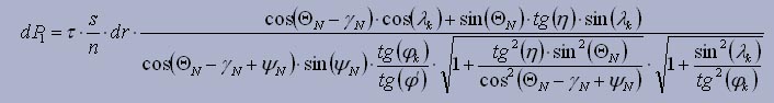
- elementary axial forming:
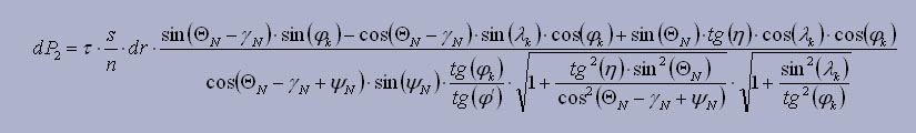
- elementary radial forming:
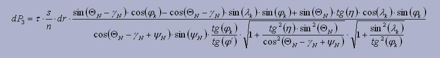
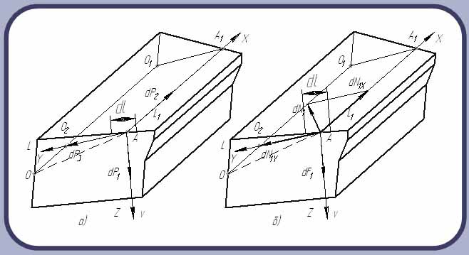
Figure 6. Scheme of power, acting on front (а) and back (б) surface teeth has checked
Were they as a result received epyury distribution forming power of the cutting, acting along the main of the cutting edge peripheral (fig. 7) and central (fig. 8) of the plates.
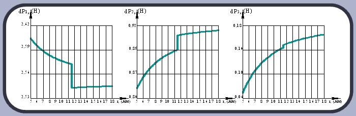
Figure 7. Epyury distribution forming power of the cutting, acting along main of the cutting edge of the peripheral plate
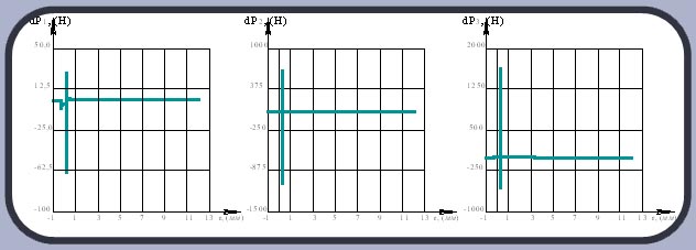
Figure 8. Epyury distribution forming power of the cutting, acting along main of the cutting edge of the central plate
5. Analysis tense-deformed conditions to designs assembly have checked
Information was received As a result of calculation about tense-deformed condition to designs assembly have checked. On fig. 9 are brought deformation to designs and her element. Deformed form of the instrument is brought For greater clarity with increase deformation in 100 once.
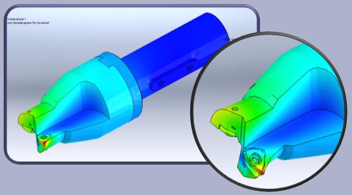
Figure 9. Tense-deformed condition to designs assembly have checked
On fig. 10 shown equivalent voltages, calculated on criterion Mizesa.
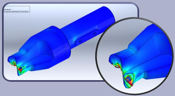
Figure 10. Equivalent voltages calculated on criterion Mizesa Findings
Conclusions
Called on modeling has shown that accounting sharing the displacement and voltages in designs assembly has checked corresponds to the real load sharing. This is confirmed that that place with maximum importances of the displacement and voltages on models (fig. 9) correspond to the places of the destruction of the cutting plates on real design has checked (fig. 1). Thereby, draw a conclusion about possibility of the using of the numerical modeling at searching for of the rational design assembly has checked, which will provide comparatively even boot the cutting edges of the instrument and increasing to his capacity to work.
Is it hereinafter planned conduct the experimental study for the reason acknowledgements of the brought forth hypothesises, with account of the change geometric parameter worker of a part has checked, power and dynamic parameter of the process.
Note:
When writing this abstract master's work is not yet completed. Final completion: December 2012. The full text of work and materials on the topic can be obtained from the author or his head after the specified date.
List of the sources
- Холмогорцев Ю. П. Оптимизация процессов обработки отверстий / Холмогорцев Ю. П. – М.: Машиностроение, 1984. – 184 с.
- Мурашкин Л. С., Мурашкин С. Л. Прикладная нелинейная механика станков /«Машиностроение», 1977. – 192с.
- Васин С. А., Маслов А. Р. Прогнозирование виброустойчивости инструмента при точении и фрезеровании / М.: Машиностроение, 2006. – 384с.
- Денисенко В. И. Управление стружкоотводом при сверлении / В. И. Денисенко// Известия высших учебных заведений. Машиностроение. – 1988. – Вып. 7. – С. 141 – 145.
- Виноградов А. А. Расчёт усадки стружки и длины контакта её с резцом / А. А. Виноградов // Сверхтвёрдые материалы. – 1990. – №2. – С.58–63.
- ГОСТ 51685-2000 Рельсы железнодорожные. Общие технические условия. – М.: Издательство стандартов, 2001. – 27 с.
- Баканов А.А., Петрушин С.И. Работоспособность сверл с СМП при сверлении железнодорожных рельсов // Современные проблемы машиностроения: Труды III Междунар. научнотехн. конф. – Томск: Изд_во ТПУ, 2006. – С. 186–189.
- Петpушин С.И., Баканов А.А., Махов А.В., Геометрический и силовой анализ сбоpных свеpл со сменными многогpанными пластинами/Технология машиностроения, Вып. 10(64), 2007. – С. 27 – 30.
- Справочник технолога машиностроителя: в 2 т. /[ред.: Косилова А. Г., Мещеряков Р.К.]. - 4-е изд., перераб. и доп. - М.:Машиностроение, 1986. Т.2 - 1985. – 496 с.
- Гринёв Ю.А. Определение статических геометрических параметров сборных сверл / Ю.А. Гринёв, Т.А. Воеводина, Е.Н. Царенко // Наукові праці Донецького національного технічного університету. Серія: Машинобудування і машинознавство. Донецьк: ДонНТУ, 2011. – Випуск 8 (190). – С. 200 – 209