
Research and development of
automated electric locomotive
traction motor drive shaft through the use of brushless motor
Contents
- Introduction
- 1. An analysis of the works on improving the electric mine locomotives
- 2. Brushless motor control circuit
- 3. Mechanical characteristics of the brushless motors
- Conclusion
- References
Introduction
The locomotive transport is the primary means of delivery in the horizontal coal mines. The relative ease of speed control and maintain a sufficient traction resulted in the use of DC motors series excitation (DCMSE) as a drive at the mine electric locomotives. However, the long experience of operating founded a number of deficiencies which significantly reduce the efficiency of the DC electric of the mine locomotives. These include the low resources and the reliability of the collector node, the anchor and the pole motor windings, increased complexity of their service. In light of this seems quite reasonable the prospect of using the brushless motors which characterized by high reliability, simplicity of design, operation, and relative cheapness, as a drive motor.
Model of Moore finite state machine (FSM, offered by E. Moore in 1956 and named in his honor), as synchronous sequential circuit, is the part of numerous digital systems and is used in construction of control devices. High complexity of integrated circuits (which is increasing, according to the G. Moore’s law) and theoretical basis of automatic calculations make possible the implementation of comprehensive algorithms of processing information. However direct realization of algorithms can lead to inefficient using of crystal’s resources and extension of project’s cost.
1. An analysis of the works on improving the electric mine locomotives
Widespread use of DCMSE in mine traction drive due to ease of speed control. In practice this is realized by means of the amplitude (rheostat system) or pulsed (thyristor system) controls of voltage of the armature winding. [1]. In this case the latter method is more acceptable. The elimination of inrush current and, consequently, tractive force allows the use of the maximum possible, given the coefficient of grip, traction and exercise on this basis, the crackdown with the utmost intensity. In addition to this switching regulator has a higher efficiency (95–98 %) and reliability compared to the rheostat system [7].
One of the first battery electric locomotives, equipped with a pulsed system of speed control, was established in Poland in 1968 [8].
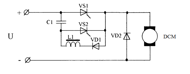
Figure 1.1 – Pulse regulation direct current
The main disadvantage of the drive with a converter which was made under this scheme is a significant loss of power which due to the pulsating shape of current and the presence of the higher harmonic components in the supply voltage. In addition to reducing the efficiency of this leads to the appearance of vibration, noise, an increase of sparking in the collector, an engine overheating.
The impulse actuator for industrial – battery electric contact was designed in 1968 in the Dnepropetrovsk Institute of Railway Engineers [9]. Speed control system consisted of two converter made by the scheme Fig. 2.1. which was working with a phase shift by a half. The tests showed a significant improvement in energy performance of the drive. Similar results were obtained at the Riga branch of the Research Institute railway car for suburban electric train [10] and also in Germany – for testing of industrial electric locomotive contact [11]. In the drive of these engines were used the two-stroke converters.
Currently, mine electric locomotives with thyristor control are widely used in mines. An example is the domestic engine ATM-14and also electric Lea-BM-12/TB (battery), Lep-18/T2 (pin), which produced in Poland [12]. Despite the improved in comparison with the rheostat operating systems and energy characteristics of the problem is not solved – the presence of an unreliable and expensive DCM. In this respect, the alternating current motors and also brushless motors have the better indicators.
2. Brushless motor control circuit
This scheme is shown in fig. 2.1. The electronic switch of ES, which provides a step change in phase voltage at the stator windings of synchronous machine SM, consists of the distributor of the pulses (DP) and inverter, which assembled in the six transistors T1–T6.
The principle of operation of brushless motor is illustrated in the diagram of phase voltage, as shown in Fig. 2.2.
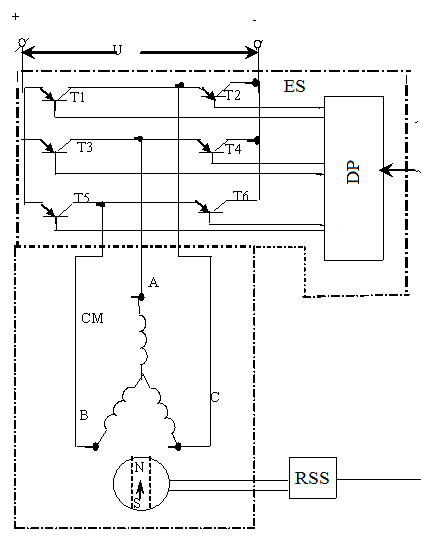
Figure 2.1 – A scheme with a step change in the magnetic field of stator.
")
Figure
2.2 – The diagram of one phase voltage
(gif-animation: 8 frames, 5 cycles of repeating, 83.4 kilobytes, 575
× 327 dpi)
By turning the the rotor brushless motor to 30 degrees the RSS issues a command through the valve pulse for switching transistors in the inverter ES.
Further, the change in voltage on the stator windings takes place by turning the rotor on every 60 degrees.
3. The mechanical characteristics of the brushless motor
The electromagnetic torque of brushless motor is determined by the ratio:
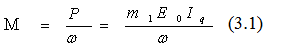
where
- Р – power of the electromagnetic brushless motor;
- m1 – the number of phases of the stator winding;
- E0 –phase EMF rotation of brushless motor;
- ω – angular velocity of the brushless motor;
- Iq – active component of the stator current in phase with Е0.
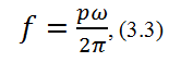
The value of Е0, in turn, is calculated as follows:
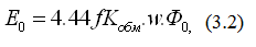
where
- f – frequency of the network;
- Kобм – factor of the stator windings;
- W – number of turns of stator phase;
- Ф0 – magnetic flux of the rotor.
Considering that the motor speed:
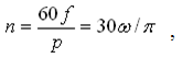
where р – the number of pole pairs, we find that
Substituting the values of (3.3) in (3.2), we obtain the following expression for the phase emf brushless motor:
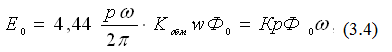
where
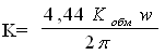
K – the coefficient, which depends from the parameters of the stator windings brushless motor.
The quantity of active component of the current in the stator is calculated as follows:
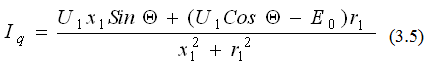
where
- x1 and r1 – reactive and active phases of the stator resistance;
- U1 – phase voltage of the stator windings;
- θ – the phase angle between.
For ordinary brushless motor (not moment) the value of θ = 30°–40° (it is determined by the actual values of х1 and r1).
For the moment brushless motor θ = 0°.
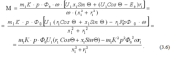
Substituting in (3.1), the value of (3.4) and (3.5), we obtain
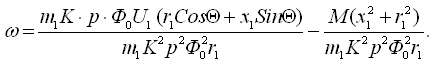
Solving (3.6) with respect to, we obtain the following equation of the mechanical characteristics of the brushless motor:
Denote KД= КpФ0. Then the equation of the mechanical characteristics of the brushless motor takes the form:
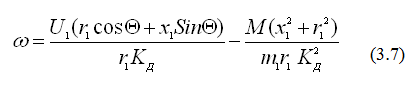
The mechanical characteristics of brushless motor in accordance with (3.7) for different values of phase voltages U1 on the stator are of the form shown in Fig. 3.1.
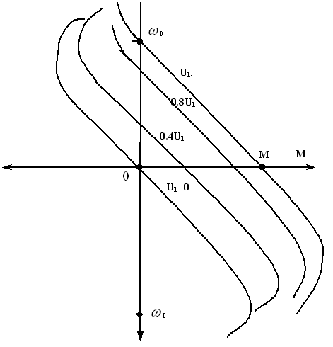
Figure 3.1 – The mechanical characteristics of brushless motor.
In motor mode (I quadrant in Fig. 3.4) and in the work area the characteristics of dynamic braking (with U1 = 0) the mechanical characteristics of brushless motor have a form close to the line. For brushless motor with low rates of rotation (the so-called torque motors), the reactance of the stator х1<< r2. In this case, taking x1 = 0 and θ = 0, we obtain from (3.7):
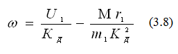
The equation (3.8) is fully consistent with the mechanical characteristics of the DC motor with independent excitation. That’s why brushless motor is also known as no-collector DC motors.
Conclusion
This paper examines the main problem of the drive with the DCMSE that consist in high cost and unreliability of such engines. It is also considered a number of developments trying to solve this problem. Nevertheless, it remains relevant, and suggests the use of valve engine as the drive as an alternative to DCMSE, free from the above-mentioned drawbacks at the same time.
In the future is supposed to develop a special scheme of the power inverter, which differs by the possibility of harmonizing parameters of the power source and the drive valve motor.
References
- Синчук О.Н., Беридзе Т.М., Гузов Э.С. Системы управлениярудничным электровозным транспортом, – М.: Недра, 1993. – 255 с.
- Волотковский С.А. Рудничная электровозная тяга. – М.: Недра, 1981. – 389 с.
- Алексеев Н.И. Оптимизация систем электрической тяги в подземных выработках. – М.: Недра, 1979. – 252 с.
- Сандлер А.С., Сарбатов Р.С. Автоматическое частотное управление асинхронными двигателями. – М.: Энергия, 1974. – 328 с.
- Маренич К.Н., Ставицкий В.Н. Актуальные вопросы эксплуатации шахтных аккумуляторных электровозов. // Уголь Украины, 1999, №6. – с. 25.
- Маренич
К.Н., Ставицкий В.Н., Ешан Р.В. Применение тиристорного триггера в
качестве инвертора преобразователя частоты. / В сб.
Наука-практика
, вып. 3, – Донецк: ДонГТУ, 1998. – с. 247–249. - Крайцберг М.И., Шикуть Э.В. Импульсные методы регулирования цепей постоянного тока с помощью тиристоров. – М.: Энергия, 1969. – 88 с.
- Czapla I., Gizinsci Z., Maliszewski I. Uklad rozruchu impulsowe dla akumulatorwych lokomotijw dolowych. // Przegl electrotechn., 1969, № 10.
- Кучма К.Г., Висин Н.Г., Пашков Ф.Е. Тиристорно-импульсная система регулирования напряжения тяговых двигателей контактно-аккумуляторного электровоза постоянного тока. // Труды ДИИТа, 1968, вып. 77.
- Доценко А.П., Бирзниекс Л.В. Двухфазный тиристорный широтно-импульсный преобразователь для безреостатного регулирования скорости электроподвижного состава постоянного тока. // Труды ВНИИ вагоностроения, 1968, № 8.
- Гейнц К., Вагнер Р. Импульсное регулирование тяговых двигателей при питании от контактной сети постоянного тока. // Elektrotechn. Z., – 1966, A87, № 5.
- Dzidovski J., Hefczyc M., Szczucki F. Koncepcja zastosowania asynhronicznych silnicow klatkowych do napedov lokomotyv dolowych. // Mechanizacja i automatizacja gornictwa, № 4, 1985. – s. 5–7.
- Пивняк Г.Г. Транспорт с индуктивной передачей энергии для угольных шахт, – М.: Недра, 1990. – 245 с.
- Ильинский Н.Ф., Козаченко В.Ф. Общий курс электропривода: Учебник для вузов, – М.: Энергоатомиздат, 1992. – 544 с.
- Электромеханические свойства электроприводов с вентильными двигателями
- Управление трехфазовым вентильным электродвигателем на основе датчиков с помощью семейства AT90USB