
Abstract
Содержание
- Introduction
- 1.Actuality of the topic, purposes and goals
- 2.Analysis of methods that provide the specified high quality and precision of surfacing
- 2.1 Subtle turning
- 2.2 The grinding
- 2.3 Method of plastic deformation
- 2.4 Conclusion
- 3. Choice of the most rational processing method for receiving the qualitative accurate surface in accordance with existing assessment criteria
- 3.1 Criterion «maximum productivity»
- 3.2 Criterion «prime cost minimum»
- 3.3 Conclusion
- References
Introduction
The development of the mechanical engineering nowadays is impossible without the constant rise of labor efficiency and conditioning of manufactured products. To solve this problem different processing methods are being developed and implemented. The subtle turning, the grinding and the plastic deformation method when processing the accurate surface of «Shaft» detail will be considered in my research.
1.Actuality of the topic, purposes and goals
Now requirements to the quality of the surfaces are considerably raised that is connected with special demands to product maintenance. It is caused by significant step forward of all process technology – the high–precision machines appeared and the tools were improved, new processing methods are being developed and implemented (it is possible to relate the method of surface plastic deformation in the flexible granulated operating environment to such processing methods).
The purpose of this research is to study the processing variants of accurate surfaces of a detail like «Shaft».
The main goal is to examine the processing methods of accurate surfaces of The main goal is to examine the processing methods of accurate surfaces of «Shaft» detail by application of turning, grinding and plastic deformation and further the most advantageous processing method should be chosen. detail by application of turning, grinding and plastic deformation and further the most advantageous processing method should be chosen.
2.Analysis of methods that provide the specified high quality and precision of surfacing
2.1 Subtle turning
This turning operation is widely used in aircraft, tractor and automotive industries in the processing of cylindrical and conic surfaces (external and internal) as well as the face surfaces, ledges, etc. The subtle boring, especially of non – ferrous metals, excels the reaming and doesn’t accede grinding on surface’s accuracy and smoothness [3].
As small cross – section of removing chip, little cutter force and insignificant raw stock’s heating have occured the considerable distorted ply on processed surface is excluded. Due to the small elastic deformations of technological system, the processing accuracy is provided by 6–8th workmanship, for non – ferrous metals and alloy materials even by 5–6th workmanship. The roughness of the machined surface of the raw stock of steel and cast iron is Ra 2,5…0,63 mkm, of non – ferrous metals – Ra 0,32…0,16 mkm [6].
As a cutter for subtle turning the following instruments are applied:
- The cutters with plates of hard alloy of VK2 and VK3M brands for subtle turning cut and internal turning of cast iron; T30K4 and T60K6 for subtle turning and internal turning of steel, light alloys and non – ferrous metals;
- The diamond cutters are for subtle turning and internal turning of light alloys, non-ferrous metals and nonmetallic materials.
The magnitude of the angles of sharpening cutters equipped with carbide plates used in fine turning is shown in Table 2.1.
Table 2.1. – Corners of sharpening cutters equipped with carbide plates used in thin turning.
The diamond cutters are more long – lived in comparison with hard – alloy ones. You are allowed to work hundreds of hours without regrinding and repurposing, and thereby handle a couple of identical details in compliance with dimensional accuracy. Two types of diamond cutters are made:
- with soldered diamonds (Fig. 2.1);
- with mechanical fastening of diamond in the bracket (Fig. 2.2).
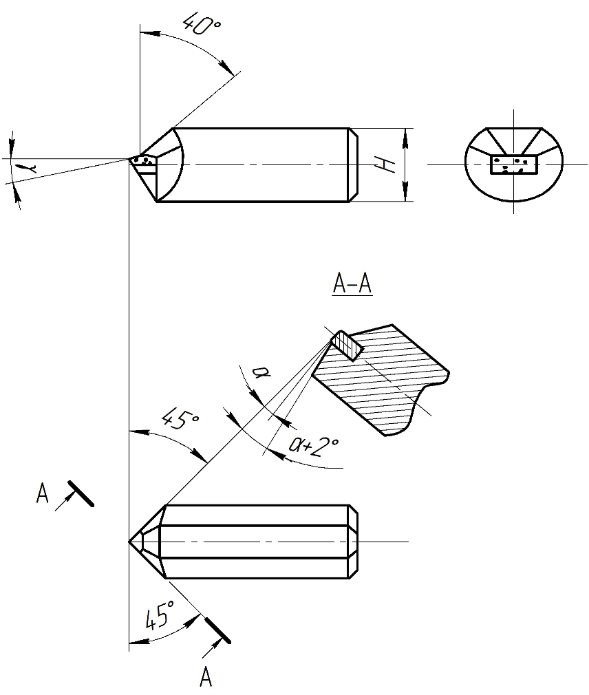
Figure 2.1 – Turning tool with brazed diamond.

Figure 2.2 – Diamond cutter with mechanical fastening diamond.
2.2 The grinding
The operations of coarse grinding, pregrinding, final and fine grinding are applied.
Figure 2.3 – Processing circuitry external grinding.
The coarse grinding provides processing without preliminary turning operation with removal of the increased allowance from 1 mm and more on diameter. It is expedient to carry out this operation on the modes of force and high – speed grinding in case vkr = 50-60 m/s. As opposed to turn process, the coarse grinding provides higher processing accuracy on 8–9th workmanship and lower roughness parameter of Ra=2,5–5,0 mkm and doesn’t require the subsequent preliminary grinding.
The pregrinding is usually performed after the turning with the increased cutting speed vkr = 40-60 m/s. The pregrinding is accomplished before heat treatment for the creation of the reference surface or as the interim operation for preparation of surface for the complete machining. In time of pregrinding the accuracy on 6–9th workmanship and the roughness surface parameter Ra=1,2–2,5 mkm are reached.
The final grinding allows to receive processing accuracy on 5–6th workmanship and the roughness surface parameter is Ra=0,2–1,2 mkm. The following cutting speed is applicable vkr = 35–40 m/s in most cases.
The fine grinding is mainly applied for receiving the roughness parameter of Ra=0,025–0,1 mkm. It requires very good pretraining as the removed allowance in case of the fine grinding doesn’t exceed 0,05–0,1 mm on diameter.
2.3 Method of plastic deformation
The surface – plastic deformation (SPD) is one of the simplest and the most effective technological ways of increasing the functionality and reliability rate of mechanical engineering products. As a result of SPD the surface hardness and durability are increased, favourable residual tensions are formed, the roughness parameter of Rа is decreased, the corner radiuses of roughness and the relative bearing length of a section are increased.
The running and the rolling methods are most widely applied with ball and roll–type gear knurlings of external and internal cylindrical, plane and formed surfaces. Examples of surface’s running and rolling by rollers are given in figure 2.3. Hard details of steel, cast iron and non-ferrous alloys are usually treated by these methods. As shown in figure 2.3., it is the diagram of cylindrical external and internal surfaces processing.
The work pieces are processed by turning, grinding and other methods that provide accuracy on 7–9th workmanships before the process of rolling and running. The machining allowance is usually recommended to be selected equal to 0,005…0,02 mm.
The surface – plastic deformation can be finishing – hardening operation (it improves the surface roughness and hardens a blanket), finishing – hardening and calibrating operation (apart from stated above, it increases the processing accuracy), finishing – calibrating operation (hardening doesn’t’ occur).
Alongside with the methods explained above, there is also the centrifugal (inertial) hardening. In this case the centrifugal force of the balls that are loosely fitted in radial holes of the fast-revolving disc is used. The diagram of centrifugal surface processing by balls is shown in figure 2.3. The balls 2 in case of the rotation of disc 3 shift in a radial direction cracking the work piece 1 and plactically deform the surface. The diamond smoothing is applied for receiving the surface with the minimum roughness parameter and the hardened layer of shallow depth. This process is similar to running, but as the tool we use the crystal of diamond which is found in special holder.
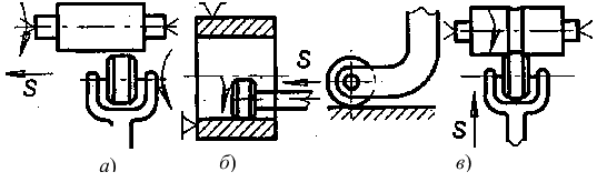
Figure 2.4 – Processing circuitry roller:а – external and internal cylindrical surfaces;б – flat surfaces; в – shaped surfaces.
The treatment by shot, hydro – vibrating processing, electromagnetic and ultrasonic hardening, etc. are considered as plastic forming methods to harden details surfaces.
2.4 Conclusion
The processing methods that provide high quality and accuracy of the processed surfaces were considered above. The complexity of the phenomena, accompanying activities of dimensional – finishing processing by edge or deforming tool, and diversity of the factors that affect the formation of roughnesses, determine a deflection of its forms and sizes from regular – shaped.
3. Choice of the most rational processing method for receiving the qualitative accurate surface in accordance with existing assessment criteria
Any technological process should be economic. When designing the technological process, there can be set up such cutting conditions, that allow to receive very high labour productivity. Thus, however, the tool durability will be low that will cause the big instrument’s consumption. Since high productive efficiency should be supported it is necessary to examine the technological factors of the cutting operation from the economic point of view.
3.1 Criterion «maximum productivity»
To provide the maximum productivity there should be minimum floor–to–floor time of processing [4].
For the turning operation, which is implemented in one pass, the floor–to–floor time is defined the following way: /p>
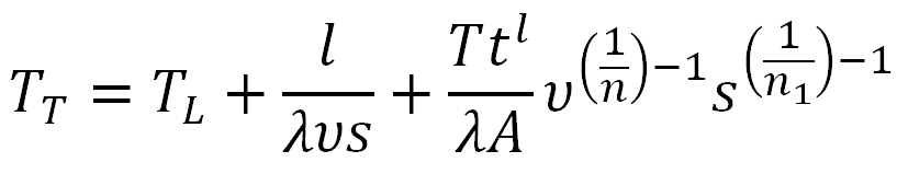
где TL – the total down time for the one detail;
Т – the tool durability;
s – supply;
1/n, 1/n1 – the exponents at a speed and supply;
t – depth of cut;
v – cutting speed;
l – length of the tool’s pass;
D – diameter of the work piece;
λ=1/πD
A=K·b-1/n2
Условие максимальной производительности можно записать в следующем виде:
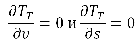
or
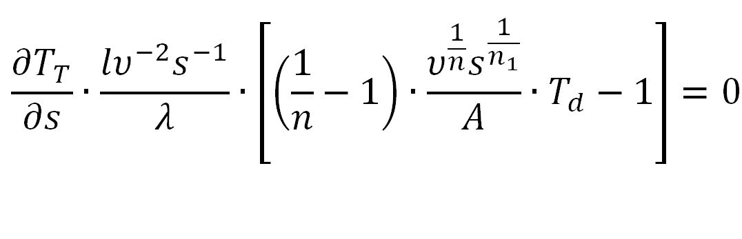
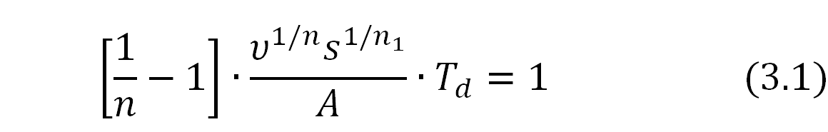
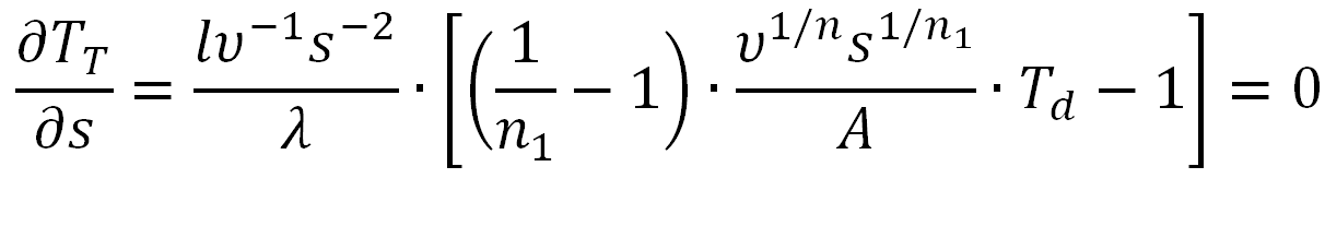
That is
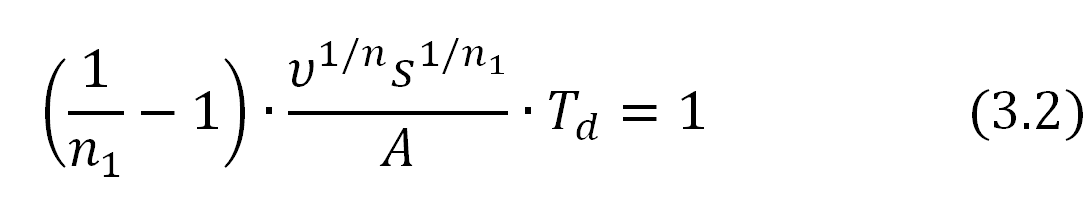
The equations 3.1 and 3.2 cannot be just at the same time and, therefore, the minimum of floor–to–floor time or the maximum productivity is not the only thing (fig. 3.1).
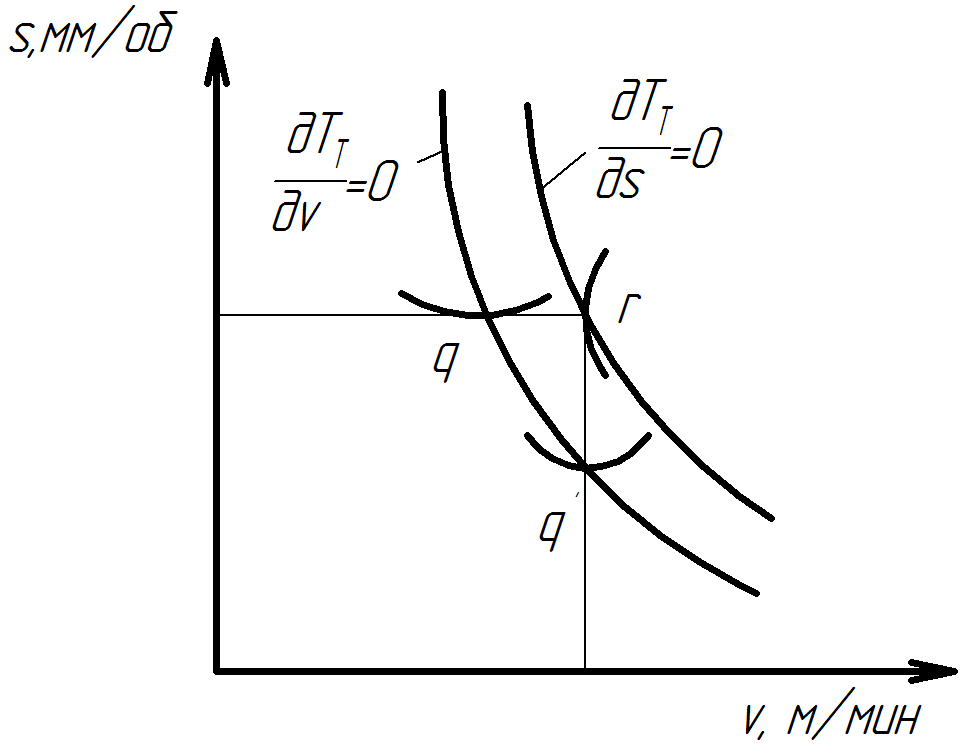
Figure 3.1 – Dependence feed s cutting speed v in the case of maximum productivity and lack of restrictions.
The greatest productivity will be reached in case of the most admissible supply and the appropriate cutting speed defined from the equation 3.2.
3.2 Criterion «prime cost minimum»
To make it simple we will examine processing by one tool.
1. The overhead for the one detail C includes the cost of fixation and removal of one detail, the equipment downtime cost. The overhead is counted at the formula where is the
х – 1 min. cost;
TL – the total down time for the one detail.
2. The cost of machine processing time of C2 is defined as multiplication of 1 min. cost of machine time x on machine processing time Tc.
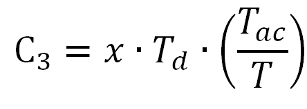
3. The time for the change of tool C3 is defined as the multiplication of 1 min. cost for the change of tool for the one detail
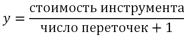
4. The tool cost related to one detail C4 equals the tool cost on the cutting blade y, multiplied by the numbers of cutting blades, used in processing of this detail.
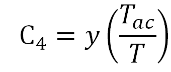
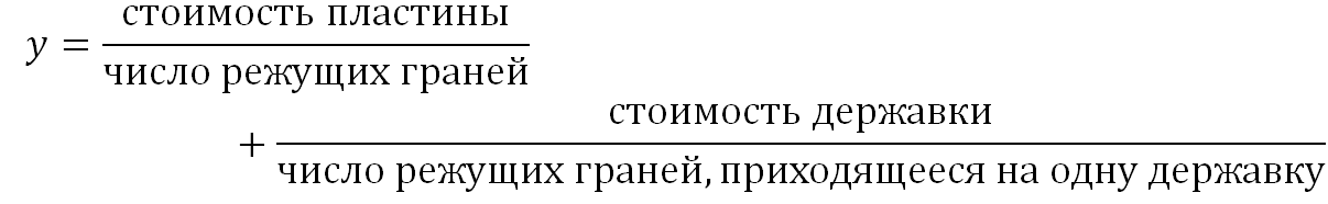
5. The tool cost of the one blade depends on a tool’s type
The prime cost includes the other expenses, such as expenses for coolant, tool development, work material, although the listed expenses, except for work material, can be included in overhead costs
Considering the equation 3.3, we see that the prime cost of a detail can be lowered by reduction of fixation and removal time of a detail, downtime and time of tool change. The influence of cutting speed on a detail’s prime cost is presented in figure 3.2.1.a. The change of floor–to–floor time (or productivity) depending on the cutting speed is shown in figure 3.2.1.b [4].
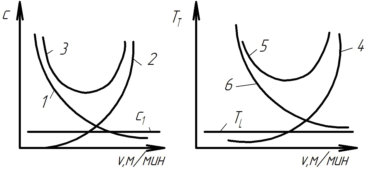
Figure 3.2 – Dependence of cost (С) and piece of time TT workpiece cutting speed v: 1 – conversion costs C2, 2 – tooling costs and shift (C3+C4), 3 – total costs (cost) С, 4 – tool change time (Td·Tac/Tc), 5 –complete (single-part) time, 6 – machine time.
3.3 Conclusion
The two assessment criteria were used to choose the most economic method of processing: «prime cost minimum» and «maximum productivity». The choice of the criterion depends on requirements specified at manufacture. Nowadays the capacity requirement at manufacture is mainly provided by a prime cost minimum.
References
- Технология машиностроения: курс лекций / А.Г. Ткачёв, И.Н. Шубин. – Тамбов: Изд-во Тамб. гос. техн.ун-та, 2009. – 164 с. – 100 экз. – ISBN 978-5-8265-0857-2.
- Наерман М.С. Справочник молодого шлифовщика. – М.: Высш. шк., 1985. – 207 с., ил. – (Профтехобразование).
- Тонкое точение. [Электронный ресурс]. – Режим доступа:http://machinetools.aggress.ru/
- Армарего И. Дж. А., Браун Р.Х. Обработка металлов резанием. Пер. с англ. В.А. Пастунова. М., «Машиностроение», 1977. 325с.
- Точение.[Электронный ресурс]. – Режим доступа:http://dlja-mashinostroitelja...
- Бойко Н.И. Ресурсосберегающие технологии повышения качества поверхностных слоев деталей машин: Учебное пособие для вузов ж.-д. транспорта.- М.: Маршрут, 2006. – 198 с.
- Шлифование металлов. [Электронный ресурс]. – Режим доступа:http://www.markmet.ru...