Abstract
Contents
- Introduction
- 1. Theme urgency
- 2. Goal and objectives of the research
- 3. Automatic gas protection in the structure of automated systems process control of mining companies
- 4. Simulation of events "blast methane-air mixtures"
- 5. Optimization of automatic gas protection
- 6. Operation automatic gas protection in nonstationary processes of methane formation
- Conclusion
- References
Introduction
The explosion of methane and coal dust mixture in the mine, accompanied by the formation and proliferation of network mining shock waves – a very dangerous kind of underground accident. Threatening the life and health of miners, explosion always leads to destruction and damage workings located therein mining equipment. At the same time social, material and financial losses may reach catastrophic proportions.
Despite the fact that the automatic gas protection system for decades operated in the mine, they cannot provide guaranteed protection, and therefore improve is actual. Modern development trend of automatic gas protection is to convert these systems in monitoring, forecasting and protection of the mine atmosphere, which calls for an integrated control of a number of parameters. Another important direction of development of these systems is to increase their reliability, foreign manufacturers offer fully redundant system protection automatic gas mining sites.
Obviously, that requires the use in mines on Ukraine new generation systems, engineering solutions with high reliability, the ability to control more parameters of the mine atmosphere, the possibility of protection from dangerous situations arising from non‑stationary processes of methane.
1. Theme urgency
During the investigation of the causes of major accidents in coal mines in Ukraine [1], it was found that in most cases the control of methane in the atmosphere excavations carried out satisfactorily. Causes of explosions in mines equipped with automatic gas protection are gasdynamic phenomena or layered appearance of methane in uncontrolled spaces. These facts point to the need for further improvement of the automatic gas protection.
2. Goal and objectives of the research
The purpose of research is to improve the reliability and the protective functions of automatic gas protection system under stationary and non‑stationary processes of methane, by changing the structure and architecture of the automatic gas protection. To achieve this goal it is necessary to perform the following tasks:
- analyze modern systems of automatic gas protection;
- develop a mathematical model that relates the structure and architecture of the automatic gas protection with a probability of occurrence of events
explosion methane‑air mixture
; - based on the simulation results to develop an optimal system architecture automatic gas protection;
- explore the work of the automatic gas protection under non‑stationary processes of methane formation;
- on the basis of research to develop an improved structure of the automatic gas protection.
3. Automatic gas protection in the structure of automated systems process control of mining companies
Automatic gas protection – provision of protective measures to prevent the possibility of mining gas contamination over allowable concentration of methane and methane‑air mixture explosion in the mines [2]. Gas protection is based on continuous monitoring of methane in mines, fixing the time of attaining the maximum permissible concentration of gas and automatic issuing protective teams to de‑energize all electrical equipment, which fell into the danger zone, turn on the alarm, enactment of additional funds for intensive ventilation and degassing emergency plot. Gas protection extends to the individual process areas, part of it, or the camera is limited to the area of operations of the mining machine.
Operating conditions are characterized by a potentially explosive environment, its high humidity, temperature, atmospheric pressure; presence in the atmosphere conductive dust, mechanical vibrations, low‑skilled staff [3].
Most existing automatic gas protection are the following disadvantages:
- Relay principle, not taking into account the dynamics of the process of methane;
- Insufficient number of control parameters of the mine atmosphere;
- Not enough high reliability;
- Inability to identify layered methane accumulation;
- Inefficient operation in the event of gas‑dynamic phenomena.
4. Simulation of events blast methane‑air mixtures
To the event occurred explosion methaneʼair mixture
should be a number of conditions, each of which is a necessary but not sufficient. Explosion event
is the conjunction of the following states: Increased concentration of methane
, presence of an ignition source
, failure automatic gas protection
[4].
Denote the event explosion
– B, the event dangerous concentration of methane
– C,
event source of ignition
– I, event failure automatic gas
protection
– А̄, then formalize event explosion
:

| (1) |
Event ignition source
is not deterministic. This event is investigated, and there are formulas to calculate the probability of this event [6].
The automatic gas protection system is restored without reservation for the connection, and in the presence of devices to prevent them [5]. Adopted elements of the device connected in series, because in case of failure of either the whole system breaks down. Construct the state graph of the system (Fig. 1)
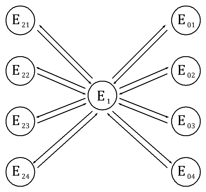
Figure 1 – State graph automatic gas protection
This figure corresponds to the state E1 good state of the automatic gas protection, state E0i – emergency simple because of the refusal of i‑th element (i=1..n) and its restoration, E2j – preventive maintenance and planned downtime j‑th element system (j=1..k). λ – failure rate, μ – intensity recovery. Index 1 corresponds to the methane sensor, 2 – link, 3 – analyzer, 4 – protective device.
Failure rate λ – conditional probability density of failure of the object defined by the condition that the time to failure of the object under consideration does not arise. Intensity recovery μ – has the same mathematical meaning.
When modeling the probability of failure of the automatic gas protection use Kolmogorov rule, compiling analytical model describing the state graph of some
system. According to this rule: the system of differential equations contains as many states contains a graph; left‑hand side contains all the equations
derived from the probability of the i‑th state; right‑hand side of equations contains as many terms as the branches of the graph associated with this condition,
if the branch is directed in this state, then placed before the term +
if part of the state, then −
, each term on
the right is the product of the intensity
of the transition from one state to another and the likelihood of the state from which emanates the arrow.
In accordance with formula (1) for the occurrence of the event B (explosion), its necessary simultaneous onset of events C, I, А̄. Since these events are independent, occurrence of one of them does not change the probability of the occurrence of another, the probability of occurrence of an event is equal to the product of the probabilities of events С, I, А̄: PB = PC ⋅ PI ⋅ PĀ
Accept the assumption that we are considering the development of always explosive concentration of methane, PC = 1, in order to simulate a worst‑case scenario, then: PB = PI ⋅ PĀ
It is known [6] that even at full protective equipment reliability (protection against leaks) cannot prevent the occurrence of an explosive source of electrical site, so PI≥0,036.
Under the condition of А̄ means inoperable automatic gas protection, which may be associated not only with the failure of the system, but also to the implementation of preventive maintenance. In accordance with state graph automatic gas protection (Fig. 1) А̄ state corresponds to any state except state E1. Since all the states form a complete group of events, then: PĀ = 1 − P1.
where, P1 – the probability that the system is able to E1.
To form the equation P1 expression relative probabilities of transition from one stable state to another, using the rule of Kolmogorov.
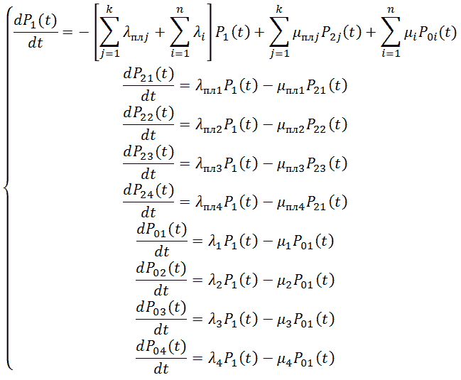
Failure rate λ is generally a function of time λ = f(t), by definition – the conditional probability density of failure of the object defined by the condition that the time to failure of the object under consideration does not arise. In practical calculations take the calculated value obtained based on the testing and operation of equipment, which are constant. At the same time the introduction of correction factors are taken into account operating conditions. Failure rate depends on the equipment used, its elemental base, methods of connecting elements, etc. and is unique for each system configuration. We consider a typical modern system of automatic gas protection mine site.
After parametric identification of the model, and solutions of the model equations numerically for a time interval of 1 year, were as follows: the probability
of occurrence of event explosion
as a function of time, quickly reaches a steady value РB = 6,6 ⋅ 10-4.
Dynamics of changes in the probability is negligible
and is shown in Fig. 2, where time is expressed in days.
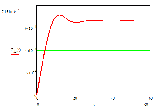
Figure 2 – The probability of an event methane‑air mixture explosion
as a function of time
The modeling the probability of the event explosion
in mines than the allowable probability of the event explosion (according to GOST 12.1.010-76 Explosion.
General requirements
, the probability of an explosion at any hazardous area during the year not exceeding 10-6) in one times.
5. Optimization of automatic gas protection
In the simulation system, which does not carry out preventive work, the results obtained by one order of magnitude higher permissible (Fig. 3), therefore, this path is not sufficient.
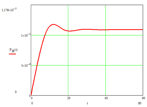
Figure 3 – The probability of an event methane‑air mixture explosion
as a function of time for a system without prevention
To meet the required probability of explosion values necessary to reduce the probability of failure on the order of elements of the system, which is possible with the use of the reserve unloaded with automatic switching. Thus reducing the failure rate of the analyzer, so in this case requires the simultaneous failure of two chips analyzer.
Availability backup controller allows not interrupt process to replace the failed equipment [7]. Reserve microcontroller must perform the same instruction set as the main. Most crucial node in such a structure is the device that performs automatic switching power supply from the primary to the standby microcontroller. The input to this circuit receives reference pulses from the main controller, the presence of which indicates normal operation of the device.
On the concept of switching devices (Fig. 4) generator G is an external output watchdog main controller. Chain R1, C1 integrate the pulsed signal.
The key elements used with MOSFET‑transistors are n‑channel type, which in a steady state fairly low power consume. Since the MOSFET‑transistors have parasitic
capacitance on the channel gate‑drain, then on their entry included follower operational amplifier, which excludes the impact of this on the capacitance of
the transistor circuit [10]. The output signal of the operational amplifier is supplied to the gates of transistors VT1 and VT2. VT1 used as the key through
which power is supplied to the main microcontroller. As long as the gate voltage of the transistor VT1 above ground potential – it is open. VT2 transistor and resistor R2
form a NAND gate. While the signal applied to the gate VT2-VT3 closed. If the main microcontroller stops feeding control impulses gate voltage VT2 is 0
, it closes and
through resistor R2 the transistor VT3, creating a backup power supply circuit microcontroller. S1 button is used to start the main microcontroller, confined, it shunts the VT1, forming
the main power circuit microcontroller. Parameters R1 and C1 are calculated from the amplitude and duty cycle control signal, which defines the voltage and frequency of
the clock generator.
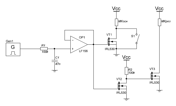
Figure 4 – Schematic diagram of the switching device
Work schemes considered modeled using the package MicroCAP. Fig. 5 shows plots of the transition process in the circuit when power is applied.
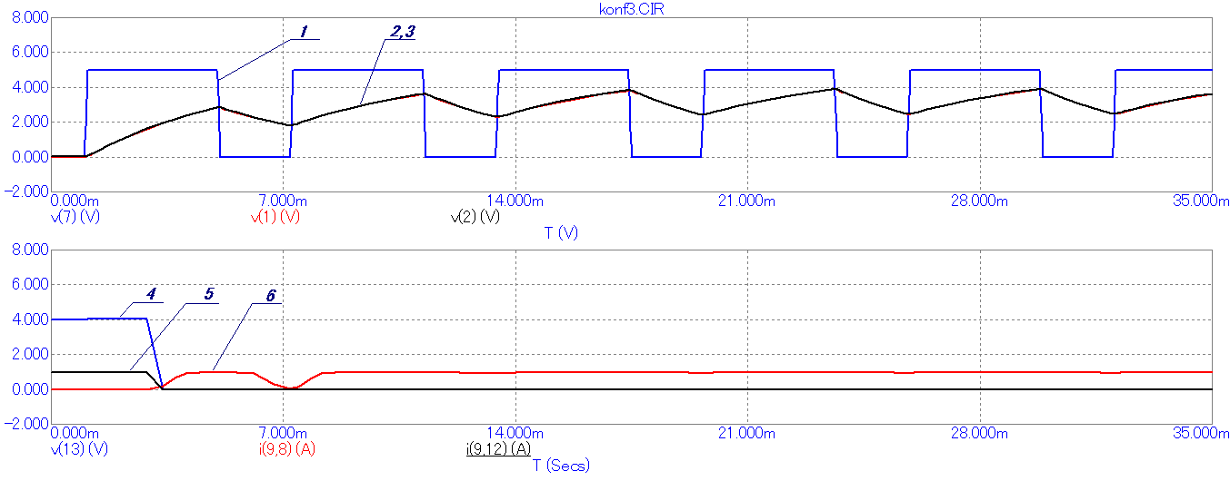
Figure 5 – Graphs of the transition process in the circuit when power is applied: 1 – test pulse 2 – output voltage RC‑chain 3 – output voltage follower op amp, 4 – gate voltage of the transistor VT3, 5 – channel current source‑drain transistor VT3, 6 – channel current source‑drain transistor VT1
Fig. 6 shows graphs of transition in case of failure of the primary circuit of the microcontroller.
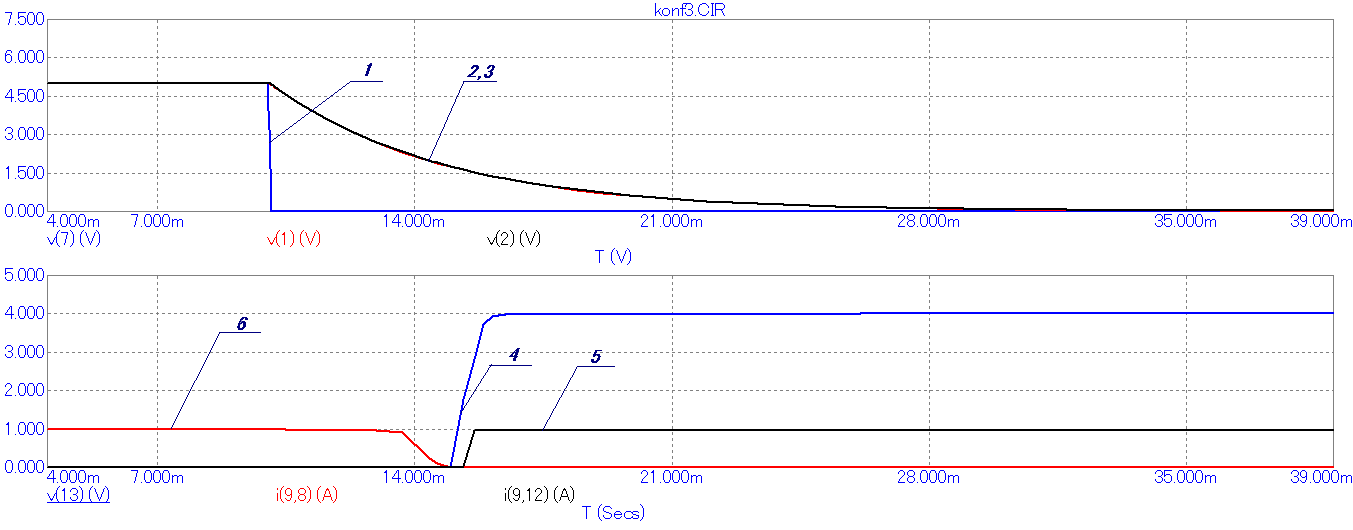
Figure 6 – Graphs transient in case of failure of the primary circuit of the microcontroller: 1 – test pulse 2 – the output voltage of RC‑circuit, 3 – voltage follower output at the operational amplifier 4 – gate voltage of the transistor VT3, 5 – a current channel source‑drain transistor VT3, 6 – channel current source‑drain transistor VT1
Thus, improve the reliability of monitoring the status of the mine atmosphere is possible due to active‑standby microprocessor protection devices.
6. Operation automatic gas protection in nonstationary processes of methane formation
When calculating air flow ventilation openings, assumption is that each unit area of coal bed allocates an equal amount of methane by volume, it is believed that methane is stationary. In this case, the concentration of methane in mine air as it moves to develop increases cumulatively. However, there are a number of processes, referred to as gas‑dynamic phenomena, in which a small area of coal bed, in a short time, the amount of methane released sufficient to form explosive concentrations.
Complexity protection from gas‑dynamic phenomena, is a transport delay, which is determined by the rate of air flow and the length of production. According to the safety regulations [8], the permissible speed air workings vd = 0.25..4 m/s. With a length of stope from 200 to 250 m, the transport component of the delay can be from 50 to 1000 seconds (Fig. 7), which is unacceptable. To improve performance, need to develop a rational structure of methane sensor arrangement.
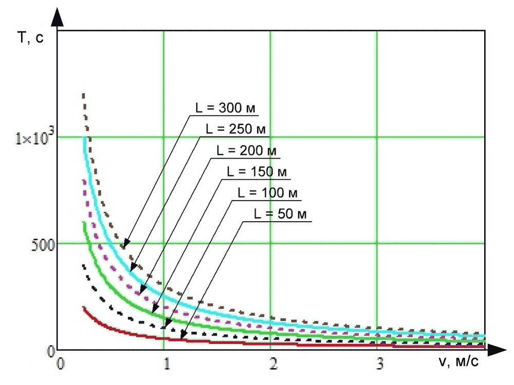
Figure 7 – Graph of vehicle delay measuring methane concentration of the air velocity and the length of production for cleaning sensor on airway
Automatic gas protection equipment monitors the methane concentration in the field of regulated safety regulations in the coal mines. However, due to the speed and air flow is not uniform for all workings layering capabilities in hazardous accumulations of methane concentrations in areas not controlled by the automatic gas protection equipment. Obviously, it is impossible to install sensors in all the places alleged accumulation of methane. It is therefore proposed integration of the mobile component in automatic gas protection. Currently distributed mining cap lamps with integrated sensor methane concentration in particular SMGV.1A.R.05, KLW4LMX etc. A promising direction in the development of the mine information management systems are positioning system miners type SPGT‑41. Is a logical combination of these technologies into one.
Conclusion
This work is devoted to improve the reliability of automatic gas protection of the mine. It examines the current trends of development of automatic gas protection,
and its prospects for improvement. The paper discusses the causes of such a state as methane‑air mixture explosion
and compiled a probabilistic model of the
event. As a result, modeling the wors
state was found insufficient reliability of gas analyzers. To eliminate shortcomings were developed and investigated
passive redundancy scheme microcontroller analyzer.
In reviewing the work of automatic gas protection in the event of gas‑dynamic phenomena, as well as layered accumulations of methane indicates that Auto‑Protect is unable to neutralize the dangerous state of the data, due to the structural features of building these systems. Further studies are aimed at ensuring the safety of operations, in the event of such phenomena.
Important! When writing the abstract of the master's work is not yet complete. Final completion: December 2014. Full text of the work and materials on the topic can be obtained after this date.
References
- Кашуба И. О. Оценка эффективности контроля содержания метана в рудничной атмосфере при крупных авариях в угольных шахтах / О. И. Кашуба, В. Н. Медведев, О. А. Демченко // Науковий вісник УкрНДІПБ, 2012, № (25). – с. 68‑78.
- Басовский Б. И. Автоматическая газовая защита и контроль рудничной атмосферы / Басовский Б.И., Биренберг И.Э., Карпов Е.Ф.; – М.: Недра, 1984 – 284 с.
- Курносов В. Г. Научные основы автоматизации в угольной промышленности: опыт и перспективы развития: монография / Курносов В. Г., Силаев В. И.; Международный институт независимых педагогических исследований МИНПИ – ЮНЕСКО, ОАО
Автоматгормаш им. В.А. Антипова
. – Донецк: изд‑воВебер
(Донецкое отделение), 2009. – 422 с. - Федорченко А. А. Микропроцессорное устройство прогнозирования опасности взрыва метановоздушной смеси в шахте / А. А. Федорченко, С. В. Василец // Автоматизація технологічних об’єктів та процесів. Пошук молодих. Збірник наукових праць ХІII науково‑технічної конференції аспірантів та студентів в м. Донецьку 14‑17 травня 2013 р. – Донецьк, ДонНТУ, 2013. – с. 369–371
- Надежность электрооборудования угольных шахт / Б. Н. Ванеев, В. М. Гостищев, В. С. Дзюбан и др.; Под ред. А. И. Пархоменко. – М.: Недра, 1994. – 255 с.
- Колосюк В.П. Защитное отключение рудничных электроустановок / Колосюк В. П. – М: Недра, 1980 – 334 с.
- Федорченко А.А. Повышение надежности мониторинга состояния рудничной атмосферы за счет резервирования микропроцессорного устройства защиты / А.А. Федорченко // Севергеоэкотех‑2013. Сборник научных работ XIV международной молодежной научной конференции в г. Ухте 20‑22 марта 2013 г. – Ухта, УГТУ, 2013. – с. 117–120.
- Хилл У. Искусство схемотехники / Хилл У., Хоровиц П. – М.: Мир, 1998. – 704 с.
- НПАОП 10.0‑1.01‑10. Правила безпеки у вугільних шахтах. Наказ Державного комітету України з промислової безпеки, охорони праці та гірничого нагляду № 62 від 23.03.2010. – 150 с.
- Шадрин А. В., Шадрина О.Я. Сравнительный анализ известных критериев текущего прогноза выбросоопасности угольных пластов // Информационные недра Кузбасса: Труды IV Всероссийской научно‑практической конференции. ‑ Кемерово: ООО
ИНТ
, 2005. – с. 84–86. - Глушко В. Т. Геофизический контроль в угольных шахтах. / Глушко В. Т., Ямщиков В. С., Яланский А. А.; Киев: Наукова думка, 1978. – 224 с.
