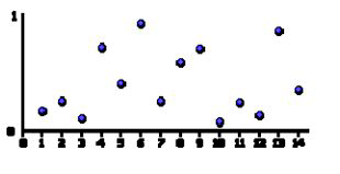
Figure 1. Pseudorandom output example.
Àâòîð: Gijsbert Santos, Eike Dehling
Èñòî÷íèê: Journal: Personal and Ubiquitous Computing — PUC , 2011, http://www.grandmaster.nu/custom/GPU-based%20clouds.pdf.
Clouds are visible in virtually all outdoors scenes of movies and games, and provide a fascinating backdrop with an endless variety of formations and patterns. Most games simply display a static background image of a sky, because producing realistic clouds is quite complex. The combination of physical and visual complexity has made them a popular research subject, as can be seen in many papers and articles on cloud related subjects produced by meteorologists, physicists, computer scientists and artists.
The Advanced Graphics course introduces programmable shading to the tools available to the graphics programmer, which when used properly vastly increase the capabilities of consumer hardware. In this paper we investigate various methods of rendering clouds in real‑time using programmable shaders. Our focus is on noise functions, a signal primitive which forms the basis for many procedural texturing techniques. We then go into more detail on how these noise functions can be used to create a cloud field. Lastly, make an overview of the various approaches used by us and make recommendations for future research.
Clouds have an irregular shape and are difficult to express in a triangle‑based model. Several procedural approaches have the potential to create cloud‑like images. One obvious approach is to simulate nature, which means implementing volumetric fluid dynamics on water vapor in the air, in a voxel field and performing raytracing to get a final image. Regrettably, both volumetric fluid dynamics and raytracing are still very costly processes, and cannot be used (at the time of writing) to create a cloud field in real‑time. Current graphics cards are not optimized for use with voxels nor raytracing, which means that even displaying results would be difficult.
As an experiment we did implement a particle‑based system that simulates a cloud field with particles, but this proved to be slow, probably because of the amount of blending involved. We chose to investigate other methods.
A different approach is to discard the notion of being physically correct and concentrating on getting the right impression of a cloudy sky. A dome or flat surface is drawn with a texture applied that makes the surface look like a field of clouds. Various methods have been used to generate a cloud‑like texture, the most popular being based on a gradient extension of lattice noise functions, which is arguably one of the main reasons for realism being associated with procedural shading: the Perlin Noise function, which was introduced as part of Perlin’s Image Synthesizer [PERLIN85, EBERT03]. As early as 2001 there has been some success in implementing this function as a graphics shader [HART01].
While our focus was mostly restricted to optimizing some form of noise texture to a sky dome, we also experimented with various other methods. Because the noise results in a single value for an input coordinate, it can be combined with implicit shape functions. For example the distance to a point space describes a circular pattern; when combined with noise, the general pattern can be distorted in a controllable fashion. Because the noise function can easily be replaced by an animated version, we successfully used this approach to create an aesthetically pleasing animated puff of smoke in 2D. The intent was to use this as a more realistic alternative to static particle images in a volumetric approach, but the number of puffs required to create a convincing cloud field remains prohibitive. See appendix D for a screenshot of a single puff created with this method.
We also experimented with a 3D extension of this concept, distorting the vertices of a spherical model, again based on the distance to a central point. This resulted in an animated object that except for the color somewhat resembled a moving soap bubble. We then applied the same method we used to create cloud structures in a sky dome to texture this object, but in our opinion the result did not bear any semblance to a cloud. See appendix E for a screenshot of the resulting object.
Many natural phenomena exhibit fractal behavior at various levels of detail. A common example is the outline of a mountain range. It contains large variations in height (mountains), medium variations (hills), small variations (boulders), tiny variations (stones) etcetera. At first glance, all of these features appear to be random, but coherent. This observation hints that the procedure we are looking for to create natural appearances is a (pseudo)random, coherent, self‑similar function.
The Perlin noise function adds randomness to procedural shading, and is commonly used to add imperfections to surfaces. A common method of producing cloud‑like images is based on a summation of the noise function at various scales, making the result self‑similar [EBERT03].
A distinct advantage of procedural texture mapping over traditional texture mapping is that
it can be applied directly to a three dimensional object, avoiding the mapping problems
of traditional texture mapping. Essentially, the virtual object is carved out of a virtual solid
material defined by a procedural texture, thus avoiding trying to distort an image to fit an
arbitrary surface. The downside is that procedural textures are a lot more difficult to control
effectively. With regular texture mapping it is relatively simple to assign colors to specific parts
of a model, while procedural texturing lends itself more to creating the appearance of
various materials such as wood, marble or lava.
See appendix A for an example of mapping problems when applying an 2D image to a 3D object. Notice how distortion changes the appearance of the textures in certain areas, notably at the pole.
A good noise function is a space‑filling primitive that gives the impression of randomness, and yet is controllable so it can be used to design various looks. A key aspect of Perlin noise is that it is deterministic and frequency band‑limited. Determinism allows it to be reliably used by artists, so that appearances do not change unexpectedly. The frequency band limits allow it to be used in a controllable fashion. By scaling the inputs, a shader designer can produce desired frequency profiles. Achieving complexity in the frequency profile can be done by combining several scales or octaves of Perlin Noise, as can be seen with fractional Brownian Motion (fBm) and turbulence functions [PERLIN85, LEWIS89].
A multitude of solutions exist to generate random values based on some input coordinate, but in this case we’re only interested in computationally simple, deterministic functions that consistently give the same results for the same input values. If true random functions are used, it is no longer possible to have exact control over the final output, making the method unsuitable for artistic usage.
In our case, because the shading language lacks support for bitwise operators [KESSEN06], many regular hashing or pseudorandom number generation schemes cannot be used directly. Eventually we used a standard random function to shuffle an array of integer values, which was then passed to the shader program as an uniform texture, effectively precomputing a set of values on the cpu. This approach seems to be making the most use out of both programming paradigms. This image shows an example pseudorandom output. Note that the output is neither coherent nor continuous.

Figure 1. Pseudorandom output example.
To achieve coherence, the random valued output has to be interpolated and oversampled. There are various possibilities to interpolate between the integer points; Perlin himself originally used the Hermite blending function f(t) = 3t2 − 2t3, but because it is desirable to have a continuous second derivative of the noise function a fifth degree polynomial was suggested: f(t) = 6t5 − 15t4 + 10t3. These two functions are, in the [0…1] domain both S‑curves that range from 0 to 1, but the fifth degree curve also has a zero second derivative at its endpoints, making it better suited for common graphics tasks that make extensive use of normal vectors or other derivatives; such tasks include for example surface displacement and bump mapping.
Of course other interpolation techniques are a possibility, such as piecewise interpolation, linear interpolation, spline‑based interpolation and so forth. The Perlin Noise standard, polynomial interpolation, is a typical case of making a trade off between speed and quality.
The image shows an example of smootly interpolated values. By interpolating the values both coherence and continuity is achieved, although the coherence in a discrete environment only becomes evident when the function is sampled at smaller intervals than the original intervals between the randomly generated numbers. Also, the smoothness is heavily dependent on the type of interpolation used. For example, straight linear interpolation is usually not smooth when interpolating from one value to the next.

Figure 2. Smootly interpolated values
In two dimensions the integer coordinate points form a regular square grid. At each point a pseudo‑random gradient vector is picked. For an arbitrary point P on the surface, the final noise value is computed from the four closest grid point gradient vectors. Just like the 1D case, the contribution from each of the four corners of the square grid cell is an extrapolation of a linear ramp with a constant gradient, which is zero at its associated grid point.
The value of each gradient ramp is computed through a dot product between the gradient vectors of each grid point and the vectors from the four grid points surrounding it [GUST05]. The interpolation of the noise contribution from the four corners is performed in a manner similar to bilinear interpolation, again using the fifth order curve to compute the final value The method can be extended to arbitrarily higher dimensions, by extending the grid to a hypercube structure, and interpolating one axis at a time. The results are then combined, also through interpolation, until a single resulting value remains.
The gradients are chosen in such a manner that the function appears random, but in fact is not. Too little variation in the gradients results in a more or less repetitive results, which are not desired. On the other hand, if the gradients are chosen with too much variation the function becomes unpredictable. Perlin suggests picking gradients of unit length evenly distributed in different directions, with around 8 gradients chosen for the 2D noise function. For 3D, Perlin’s recommended set is the midpoints of the 12 edges of a cube, centered on the origin. Choosing midpoints of a cube can be extended to arbitrary dimensions. The advantage of using the midpoints over random gradients is a computational one, and lies in the fact that using dot product switch these does not require multiplications, only additions and subtractions. The chosen set of gradients is then associated to the grid points through a simple hashing scheme.
See appendix A for visual examples of perlin noise applied as a texture mapped to a sphere.
As described above, traditional Perlin noise makes extensive use of numbers which are aligned in a grid, between which is interpolated. For low dimensions this is an effective approach, but the complexity scales rather badly. The reason for this is that a hypercube subdivision scheme of N‑space fills the space with N‑sided hypercubes with 2n corners, which makes the complexity O(2n).
A different approach is to tessellate N‑space with the simplest compact shape that can be repeated to fill the entire space. In one dimension this means intervals of equal length, placed directly after one another. In two dimensions the simplest space‑filling shape is an equilateral triangle. Two of these can be combined to form a rhombus, which can be described as a skewed square. This approach results in a transformation from a regular square grid to a regular triangle‑filled grid, which can also be extended to higher dimensions, for example in three dimensions the simple space‑filling shape is a regular tetrahedron, six of which can be combined and skewed to fill a cube.
The simple tessellation shape (simplex) for N dimensions is a shape with N + 1 corners, N! of which can be combined and skewed to fill a N‑dimensional hypercube. The simplex corners scale linearly with dimensions, which reduces the complexity of the interpolation problem to O(N).
In effect, simplex noise replaces cubic lattice with simplical lattice, which becomes a faster approach upward from three‑dimensional input. Perlin suggests this as the preferred type of procedural noise when determining noise for higher input dimensionality ranges, such as procedurally texturing animated BDRFs. Animation adds an extra dimension to the input, so this becomes the algorithm of choice with most animated solid texturing applications.
Apart from the computational complexity, computing the analytic derivative becomes increasingly difficult when using the traditional Perlin noise approach in higher dimensions. For this reason we used a different approach, based on signal processing theory – a signal reconstruction kernel approach inspired largely by antialiasing techniques [WOL04].
Using this approach, the contributions of the simplex corner points are in fact multiplications of a symmetric attenuation function. This function then uses a pseudo‑random gradient vector which is determined in the same manner as with classic Perlin noise. The radial attention function is chosen so that the influence from each corner reaches zero before reaching the next simplex. By doing so, valuesfrom inside a simplex can be determined by summing only the contributions from the simplex corners.
All that remains now is determining for a given input coordinate exactly which simplex corners surround it. The method we have used performs this in two steps – first, the input coordinate space is skewed along the main diagonal so that each block of N! simplices transforms into a regular axis‑aligned N‑dimensional hypercube. Once this is done, taking the integer part of the input coordinate determines which hypercube is applicable. The second step involves choosing one of the N! simplexes. This can be done by comparing the magnitudes of the distances in each dimension from the hypercube origin to the point in question.

Figure 3. Grid transformation and simplex selection procedure [GUST05]
The fact that the noise function is band‑limited allows creation of a noise function with a controllable rate of variation. This permits usage of the noise function in spectral synthesis methods, which are representations of a complex function fs(s) by a sum of weighted contributions from another function f(x): f(x) = ∑iwif(si × x).
Parameter scales si are usually chosen in a geometric progression, such that si = 2si − 1, and weights wi = ½w i &minus 1. Each term in the summation is also known as an octave, because of the doubling in frequency.
When spectral synthesis is used with the Perlin noise function the result is referred to as fractional Brownian motion (fBm). Doing this allows one to vary the level of noise returned by the function, while maintaining well‑defined frequency content.
A similar method to fBm is the turbulence function. The approach is identical to fBm, except that it uses absolute values in the summation process: fs(x) = ∑i × wi | f(si × x)|.
Doing this introduces first‑derivative discontinuities in the resulting function, which leads to infinitely high frequency content. Even so, when written to a texture the result of turbulence gives a more cloudy impression than fBm.
The fBm function’s result can be interpreted in various ways, in our early experiments we used it to control both the color and transparency values of the pixels in a sphere that represents a layer of the sky. This was combined with a threshold value to create large open spaces between the clouds. A higher threshold value produces fewer clouds and more clear sky, while a low threshold leads to a very clouded sky.
This was then changed to affect the color and transparency in different ways; the threshold approach remained for the transparency aspect, and while the color aspect remained influenced by fBm, it was altered. Both the color and the transparency remain linearly dependant on fBm, but choosing the coefficients positive for the transparency and negative for the color made the clouds appear to have light edges and a slightly darker center. Doing this is hardly physically correct, but it does give the intended impression of clouds.
In the later stages of our project we worked on an approach that uses the fBm output as a density function, which when combined with a couple of assumptions could result in a slightly more realistic lighting model with single scattering, hopefully giving a more volumetric feel to the clouds. In effect this is a simple form of ray tracing. The basic idea is to consider the cloud layer to be more dense where the fBm function returns higher values. If a more or less flat base for the clouds is assumed, and that the clouds are always viewed upon from below, a simple ray tracing scheme can be applied. Although light travels from its source to its destination, only the rays that actually hit a pixel are of consequence. This can be determined in a straightforward manner by casting rays from the camera to the light source.
For every pixel in the screen that belongs to a cloud, the ray going from the camera to the pixel and intersecting the cloud is hitting in the bottom part of the cloud, the blue dot in the picture. The light leaving that point toward sour eye is the same light entering the cloud from the sun direction at the red dot. We assume that the farther a light beam traverses through the cloud, the more light attenuation happens. In effect, light coming from the sun will lose energy when traversing through the cloud. To quickly determine the total cloud density traversed by a ray, a basic ray marching algorithm was used, which samples the density of the cloud at evenly spaced positions. This allows us to estimate the total density, which is then used to determine the color aspect of the pixel.
Because we anticipated that a naive approach, where sampling the density is done by evaluating the fractal at the desired coordinates would be too slow, we modified our rendering process to compute the fractal to a texture, which could then be sampled multiple times relatively efficiently by a second shader in a separate rendering stage. While this approach is more comprehensive and more physically correct than our earlier approach, we did not observe a significant improvement in cloud appearance. See appendix B for a screenshot of this approach.
A slight improvement in image was achieved in another manner, namely by adding a distance‑based exponential fog factor. Because we used the programmable pipeline for every visible object, fog had to be implemented manually on a per‑pixel basis: f = e−(fogDensity − zDistance). This fog factor was applied to every object in the final scene to improve the image coherence and reduce aliasing issues.
Textures are projected onto objects using texture coordinates, the texture coordinates define where which part of the texture is placed on the object. At each vertex in the polygon mesh of the object these coordinates are defined. The graphics card interpolates between these coordinates to fill the polygon between the vertices with texture content.
At first we used a large sphere to project the cloud texture on. This was problematic, because it is not possible to project a rectangular texture onto a sphere without distortion. This was clearly visible at the north and south poles of the sphere with the sky.
At first we solved this by using a 3D texture. 3D texture coordinates can be set on the sphere such that the clouds are not distorted. However, this made calculating the noise texture much more expensive. The screenshot in appendix B shows what the sky looks like using this method.
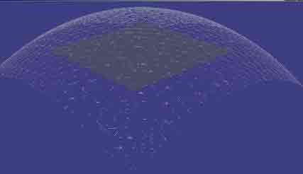
Figure 4. Sky dome
Finally we changed the sphere into a grid with the vertices placed on a half‑sphere. Except for at the edges the texture is not distorted, so an animated 2D texture is adequate once more. When compared to the sphere with animated 3D texturing method, this improved the frame rate by over 50%.
We implemented relatively simple cloud generation algorithms, varying in dimensionality and programming paradigm, and must conclude that although it is possible on commodity hardware to calculate animated solid textures the process is slow and in the case of clouds physically incorrect. That being said, it does give a good looking impression of a cloud field, and even though animating the field by extending the inputs for the noise function with an extra dimension makes it a lot slower, the end result is convincing enough to warrant the extra computation time
We only experimented with a single simple lighting model, but expect there is significant improvement in image quality to be made in this aspect, for example by implementing multiple forward scattering and self‑shadowing. We also feel that much of the aliasing issues could be dealt with on a procedural level, which would make the fog factor a purely aesthetic addition.
In the section on different approaches to create clouds, one approach we mentioned was deforming a sphere using a noise function. We suspect that this approach could be used to create a cloud model by changing the base model to an ellipsoid, increasing the number of vertices, applying fBm instead of noise and using some form of ray marching to determine the final colors. We feel this approach is promising enough to warrant a research project of its own.
In conclusion, creating cloud images with procedural texturing quickly produces reasonable results. Because care has been taken to keep the base noise functions coherent and well behaving, it is possible to manipulate the final result in great detail, at the cost of computing time. The various parts from the complete cloud‑generation algorithm are fairly diverse, making it difficult to improve upon. Moving to the simplex‑based noise has been a complicated, but rewarding choice that enables real‑time usage of noise in higher dimensions. Even though the advantages are not apparent for the result in 3D, where the frame rate remains roughly the same as with classic Perlin noise, there are many applications for noise that use higher dimensions. For those applications the reduced algorithmical complexity is a great asset, and we believe that using this technique we can look forward to consumer applications that use animated solid texturing to generate a more natural appearance of various surface types
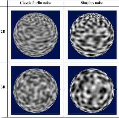
A. A visual comparison between classic perlin noise and simplex noise [GUST05]
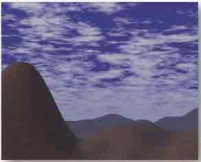
B. Screenshot showing a cloud sphere, procedurally textured with a Perlin‑based 4D fBm function

C. Screenshot showing a sky plane, procedurally textured with a simplex‑based 3D fBm function

D. Screenshot showing an animated sprite, using a combination of an implicit function with noise
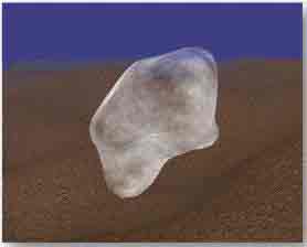
E. Screenshot showing a sphere, with the vertices distorted using a noise function. The texturing was done procedurally with a 4D fBm technique
[EBERT03] David S. Ebert, F. Kenton Musgrave, Darwyn Peachy, Ken Perlin, and Steven Worley, Texturing and Modeling, A Procedural Approach Third Edition, Morgan
Kaufman Publishers.
[GREEN05] Simon Green, Implementing Improved Perlin Noise
, GPU Gems 2: Programming
Techniques for High‑Performance Graphics and General‑Purpose Computation,
Addison‑Wesley 2005
[GUST05] Stefan Gustavson, Simplex Noise demystified, Linkoping University,
Sweden, 2005
[HART01] John C. Hart, Perlin Noise Pixel Shaders, Proceedings of the ACM
SIGGRAPH/EUROGRAPHICS workshop on Graphics Hardware, 2001, pp 87–94
[KESSEN06] John Kessenrich, The OpenGL Shading Language v1.2,
2006, http://www.opengl.org/registry/doc/GLSLangSpec.Full.1.20.8.pdf.
[LEWIS89] J. P. Lewis . Algorithms for Solid Noise Synthesis
, SIGGRAPH 1989
[PERLIN01] Ken Perlin, Noise Hardware, SIGGRAPH 2001 Course Notes, Real‑Time Shading
[PERLIN02] Ken Perlin, Improving Noise
, Computer Graphics; Vol. 35 No. 3,
2001, http://mrl.nyu.edu/~perlin/paper445.pdf.
[PERLIN03] Ken Perlin, Implementing Improved Perlin Noise
; GPU Gems, pp 73–85
[PERLIN85] Ken Perlin, An image synthesizer
, SIGGRAPH 85: Proceedings of the 12th annual
conference on Computer Graphics and interactive techniques, 1985, ACM Press,
pp. 287–296
[QUI02] Inigo quilez, Dynamic Clouds
,
2005, http://rgba.scenesp.org/iq/computer/articles/dynclouds/dynclouds.htm.
[WOL04] George Wolberg, CRC Handbook of Computer Science and Engineering, Ed. by
A. B. Tucker, CRC Press, 1997, 2004, chapter 39 – Sampling, Reconstruction, and
Antialiasing, http://www-cs.ccny.cuny.edu/~wolberg/pub/crc04.pdf.