
Abstract
Содержание
- Introduction
- 1. Relevance of the topic
- 2. Purpose and objectives of the study
- 3. General information.Category of power supply reliability
- 4. Principles pf organization of nutrition of medical equipment.Uninterruptible power supplies (UPS) for guaranteed power supply
- 5. Choice of power supply scheme for the city hospital №1
- 6. Choice of batteries
- References
Introduction
A number of special electric consumers in continuous and complex TP can also be called "responsible", since even a short break in power supply is unacceptable for them. Uninterruptible power systems (SBEP), as a kind of special BOT, appeared in the 70s of the 20th century, which was due to increased demands on the quality of supply voltage and development Continuity and high quality of supply voltage are a necessary condition for the normal operation of a variety of electricity consumers.
1. Relevance of the topic
Approbation of methods for selecting an uninterruptible power supply and a battery for the electrical shield of an operating medical institution.Selection among the options of the scheme of power supply with the reservation of electric receivers of a special group.
2. Purpose and objectives of the study
Apply the power supply scheme of electric receivers of the 1st category of a special group taking into account the requirements of IEK 60 364-710 2001.
3. General information.Category of power supply reliability
In accordance with the nature of the damage that can be caused to the enterprise due to power outages, all consumers, according to the Rules for the installation of electrical installations (PUE), are divided into three, and in fact in the four categories.
I category: electric receivers, power failure, which can entail a danger to human life, significant damage to the enterprise, mass production marred, the upset of a complicated technological process, a threat to the security of the state, the disruption of the functioning of especially important elements of the municipal economy, objects of communication and television.
Electric receivers of the 1st category should be provided with electricity from two independent power supplies. A power break is allowed while the backup power source is switched on.
I-st category, special group:Electric receivers, uninterrupted operation of which is necessary for accident-free shutdown of production in order to prevent the threat of human life, explosions and fires. For health care institutions, see GOST R 50571.28 clause 710.556 «Ensuring safety».
To provide power to a special group of electric receivers of the first category, additional power must be provided from the third independent mutually reserve power supply. As a third independent power source for a special group of electric receivers and as a second independent power source for the remaining electric receivers of the first category, local power stations, power stations of power systems (in particular, generator voltage lines), uninterruptible power supplies, batteries and m.
II category: electric receivers, power supply failure of which is associated with a massive lack of production, idle workers, machinery and industrial transport. The electric receivers are supplied on two independent lines, the break is allowed for the time necessary to switch on the backup power by the on-duty personnel or the visiting operational brigade.
III category: all other electric receivers. A break in electricity supply does not cause significant damage. The duration of the break is determined by the necessary time to replace the out-of-order electrical equipment, but not more than a day. According to IEC 60364-7-710.2001, depending on the type of medical procedures performed in the premises, their following classification is provided:
•Gr-1 honey. premises where electrical appliances are used, but a power failure can not lead to death or serious damage to the life of the patient;
•Gr 2 - premises where the primary malfunction in the power circuit should not lead to the failure of life support equipment.
The premises of Gr2 include: operating rooms, intensive care rooms, anesthesia rooms, preparation rooms for surgery, postoperative recovery rooms, an artificial heart and a room with infants.
To power electrical appliances in the premises of medical institutions of Group 2 in order to ensure maximum electrical safety, it is prescribed to use isolating transformers with a network isolation monitoring system (isolated neutral mode or IT network). The main method of obtaining an IT network is the use of a separation transformer (Figure 3.1).
The load is connected to the power outputs of the transformer, and the device housing to the ground bus to prevent the accumulation of static charge.
If a three-phase transformer is used, the output voltage can be either 220/380 V 50 Hz or three-phase 220 V 50 Hz without neutral, where the single-phase load is connected to the line voltage.
The use of isolation transformers with insulation control systems is quite expensive, but it has several advantages:
- Increased reliability. Primary breakdown (phase - housing), unlike TN-S networks, does not lead to an accident.
In the absence of an insulation monitoring device, this situation can go unnoticed, so for networks with isolated neutral it is mandatory to use an insulation monitoring relay (RCT) that provides continuous monitoring of the insulation state of the transformer's output winding and the distribution network.
- Increased safety. Simultaneous contact of a grounded, non-insulated structural element and any of the power outputs of the isolating transformer is safe. In real networks leakage currents make up microamps, which is much lower than the level of safety currents and does not pose a threat.
- The isolating transformer is a filter of interference and protection against impulse, lightning surges, which provides more reliable operation of the connected equipment. This property is often used to ensure reliable operation of digital equipment in enterprises in conditions of high level of interference from equipment operation.
- Fire safety, because in the breakdown of insulation, the current of the damage is negligible and there is practically no danger of ignition, which is of no small importance in rooms with combustible materials and medical gases;
- Convenience of maintenance, tk. The fault is detected by the insulation, temperature and current monitoring system.
As a result, high reliability, electrical safety and noise immunity of IT networks have determined their use in the petrochemical industry, in mines, in transport and in medicine.
For the medical equipment networks, the threshold level of the insulation resistance of the IT network is 50 k?, which corresponds to a leakage current of 4.4 mA.
In medical premises Гр2 the IT system should be used for circuits feeding medical electrical equipment, which serves to support the vital functions of the patient and the operation. For each group of rooms with similar functions, at least one IT system is required, with each IT network being fed from a separate source.

Figure 1 – Isolation transformer for medical IT networks
4.Principles pf organization of nutrition of medical equipment.Uninterruptible power supplies (UPS) for guaranteed power supply
- Switching time is less than 0.5 seconds. The UPS must ensure that the operating tables and other important objects are illuminated for at least 3 hours.
- Switching time is less than 15 seconds. The UPS must provide work within 24 hours (time can be reduced to 3 hours if the specifics of the institution allows for this period to finish the procedures and evacuate):
•emergency lighting;
•elevators for the movement of firefighters;;
•ventilation systems for smoke removal;
•medical equipment for gas supply;
fire alarm and fire extinguishing systems.
- Switching time more than 15 seconds. The UPS must operate for a minimum of 24 hours:
•sterilization equipment;
•technical services for building maintenance, incl. ventilation and air conditioning, heating, garbage disposal;
•refrigeration equipment;
•equipment for cooking;
•devices for charging batteries.
- The switching time for emergency lighting is no more than 15 s. The UPS must provide lighting:
•evacuation routes;
•exit signs;
•premises in which emergency power generators and switchgears of the main and emergency power grids are located;
•emergency rooms and rooms Gr. 1 (in each of them at least one luminaire must be connected to the emergency network);
•premises Gr. 2 (in each of them not less than 50% of the fixtures should be connected to the emergency network).

Figure 2 – The option of organizing a medical IT network for powering the operating room
5.Choice of power supply scheme for the city hospital №1
Consider the features of the existing scheme of power supply GB No. 1 (city hospital No. 1). In it, to ensure uninterrupted power supply, a diesel generator set is provided, which in the event of an accident can take the entire load on itself and operate autonomously for 200 hours. But since contactors are used for the automatic input of the reserve (diesel generator) and the time of reception of the load by the automated diesel generator from the first attempt from the state of the hot reserve is 10-20 seconds, then in one of the operating or several operations can occur.
At this time, the light on the operating table may go out, the medical electrical equipment may be disconnected, for example, artificial ventilation, artificial kidney, artificial circulation, etc. If there is a loss of nutrition in these life-saving appliances, there is a threat to the patient's life.
In the event of an emergency, the existing power supply system is unreliable in the operating unit itself. if there is a short circuit in the main board of the operating unit, electrical shields located on the floors, also located in the operating rooms themselves, then talking about uninterrupted power supply is useless, since in order to find the place of an accident and repair a malfunction a time that is from several minutes to several hours.
Also short circuits, breakages can occur in tap-off lighting boxes, sockets, switches.
Therefore, to prevent the tragic consequences of this scheme of electricity must be transferred to electricity by the 1st special group.
Since it is unacceptable even for a short-term shutdown in surgical operating rooms, it is proposed to equip each operating room with a separate unit with guaranteed power supply to provide a more reliable power supply, since in the event of an accident the probability that the operating room will be left without electricity is minimized.
The power supply of the operating unit is carried out according to the first category of power supply from two independent power supplies-the transformer substation of City Hospital No. 1 TP-8 with the ATS between the supply lines. Also in the power supply diagram of the operating unit is a diesel electric installation that reserves the entire load of the operating unit. Switchings occur between the feeder contacts of the network feeder and the generator feeder.

Figure 3 Diagram of power supply for the operating unit and control panel of the DEU(animation: 8 frames, always repeated, 91 kilobytes)
Option number 1. Using a local UPS provides the 1st category, a special group and a continuous (class 0) power supply. The operating time of the uninterruptible power supply is determined by the start-up time of the DGU or, in agreement with the customer, the end-of-operation time. Due to the built-in AVR in the cabinet of the medical separation transformer, there is no need for a BYPASS service. Priority is the operation of the transformer from the line with the UPS (Figure 5.2).
Option number 2. Applicable provided that the installed medical equipment has built-in batteries, including a system of surgical lamps
Option number 3. The installation of a centralized uninterruptible power supply can be more justified for the following reasons:
The cost of one powerful UPS is lower than a few local ones, especially taking into account the simultaneity ratio.
The centralized UPS is installed in a dedicated room with the necessary ventilation system and the attitude of the operation service to a powerful source is more "trepid" and attentive, which undoubtedly affects the reliability of the operation of the centralized UPS.
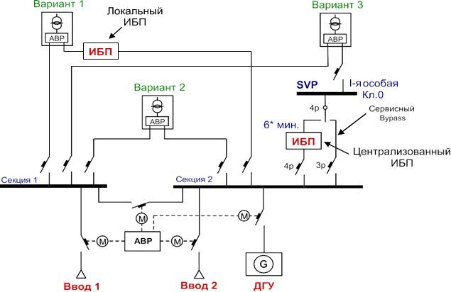
Figure 4 – Options for reserving the electrical receivers "special" group I category
6.Choice of batteries
Calculation method with constant power consumption
Set: The total power consumption of 1800 W * h and the time required for continuous operation from the batteries - 1 hour.
Select the type of uninterruptible power supply (UPS), depending on the total power consumption (power factor for power for 0.8).
We choose the UPS in terms of power. Required power 1.8 kW (from the catalog powercom.ua/ru/products/item/120/) we choose a multifunctional UPS of the On-Line class with double energy conversion VGD-3000 RM-2U- UPS (Figure 9.8) high quality power supply ( power 3000 VA / 2100 W). The Vanguard series is designed to protect servers, workstations, communication equipment (routers, switches, telephone exchanges, etc.), automation, surveillance and monitoring devices, medical equipment and other loads that require high quality power. The possibility of separate control of the load segments allows for a step-by-step disconnection of the loads when the input voltage is lost using the energy of the storage batteries most effectively.
The Vanguard series allows you to protect both stand-alone devices with a capacity of 700 VA (a small server) and medium and powerful computing or communication systems entirely, the consumption of which does not exceed 3000 VA.
The battery voltage in the UPS is 12 volts, the number of batteries is 6 pieces, the capacity of each battery is 9 A / h.
The required battery capacity is determined:Have received 187,5 (Ah)
Determine the required amount of energy:We get 2250 (VA / h)
We determine the power reserve of the batteries built into the UPS:We get 648 (VA / h)
Determine how much energy should be added to the built-in UPS batteries:We get 1602 (VA / h)
Based on the data we select Yuasa NP24-12I rechargeable batteries. Battery voltage 12 V. Battery capacity 24 A / h.
The Yuasa NP24-12I battery is a sealed, maintenance-free, lead-acid battery with a life of 6 years.
Determine the amount of energy of one battery:We get 288 (VA / h)
We find the required number of batteries:We get 6 (pcs.)
Determine how much energy will be provided by the six Yuasa NP24-12I battery packs:We get 1728 (VA / h)
We determine how much energy will be provided by the guaranteed power unit:We get 2376 (VA / h)
We compare the obtained data with the calculated ones:We get 2250 <2376 (VA / h)
The batteries have been selected correctly.
References
- Технический регламент «О безопасности при нарушениях электроснабжения». Проект. Версия 2. Москва 2006. Интернет-ресурс http://www.vniie.ru.
- Портной М.Г., Рабинович Р.С. Управление энергосистемами для обеспечения устойчивости. М.: Энергия, 1978. 352 с.
- Гарганеев А.Г. Особенности проектирования медицинских систем беспере-бойного электропитания на базе статических преобразователей напряжения // Пробле-мы современной радиоэлектроники и систем управления: Материалы Всероссийской научно-практической конференции, посв. 40-летию Томского государственного уни-верситета систем управления и радиоэлектроники. Томск, 2–4 октября, 2002 г.: В 2 т. Т 2. С. 14–16.
- Гарганеев А.Г. Применение систем бесперебойного электропитания в экстренной медицине // Известия ТПУ, 2005. №6. C.166–171.
- Уильямс Т., Армстронг К.. ЭМС для систем и установок. М.: Издательский Дом «Технологии», 2004. 508 с.
- Источники вторичного электропитания / В.А. Головацкий, Г.Н. Гулякович, Ю.И. Конев и др.; Под ред. Ю.И. Конева. 2-е изд., перераб. и доп. М.: Радио и связь, 1990. 280 с.
- Вайлов А.М., Эйгель Ф.И.. Определение параметров схемы замещения аккумуляторной батареи // Электротехническая промышленность. Сер. Химические и физические источники тока. 1984. Вып. 3 (96). С. 12–13.