
Content
- Introduction
- 1. Relevance of the topic
- 2. Types and causes of unbalance in rotors
- 3. Balancing rotors in their own supports
- 3.1 The method of amplitudes (the method of three starts)
- 3.2 Method of amplitudes and phases
- 4. One- and two-line balancing
- 4.1 Balancing in one plane
- 4.2 Balancing in two plane
- 4.3 Selection of measurement points and correction planes.
- Conclusion
- References
Introduction
Currently, many different methods of dynamic balancing have been developed. Their principle is generally the same. The difference is mainly in taking into account specific features of balancing objects, specific technical means of vibro measurements and the availability of computer technology. Often the difference in methodologies is determined by the choice of the criterion by which the balancing results are evaluated: - minimization of RMS residual levels of vibration; - minimization of average residual levels of vibration; - minimization of the greatest of vibration levels by control points, etc. However, in all cases, any balancing technique is based on one assumption, the adoption of which allows both the development of theoretical aspects of the problem, and makes it possible to practically balance all rotary mechanisms in general. The essence of the assumption is the assumption of the linearity of the oscillatory system relative to.[ 1 ]
1. Relevance of the topic
One of the features of modern technological progress is a systematic increase in the operating speeds of rotors of machines, devices and mechanisms. For example, the rotation speed of rotors of centrifuges reaches 500 thousand rpm, and some parts of textile machines - up to 1 million rpm. It is quite natural that with increased rotation speeds there are also increased vibrations.
Vibrations arising from the operation of machines and mechanisms create additional loads on parts, increase their wear, decrease the service life of products, and have an unfavorable physiological effect on the human body. Destruction of the supports and foundations of cars, increased wear of automobile tires, poor playback of tape recording - all this and more in most cases is associated with a high level of vibration. Therefore, the fight against harmful vibrations is an actual problem of modern machine building and instrument making. At the same time, vibrations used in the operation of molding and casting machines, when piles and pipes are buried in the ground, when compacting concrete and in many other production processes, are useful.<[ 2 ]
2. Types and causes of unbalance in rotors
Static imbalance is the state of the rotor, in which the rotor axis and its central axis of inertia are parallel, i.e. the center of mass of the rotor is displaced from its axis, which causes centrifugal force. The magnitude of the rotor imbalance is estimated as the main vector of the static imbalance.
Momentary imbalance is characterized by the fact that the center of mass of the rotor is located on the axis of its rotation, the main central axis of inertia is rotated about an axis of rotation by some angle. Momentary imbalance manifests itself only when the rotor rotates, in the form of beating in the supports, and a dynamic moment arises.
Dynamic imbalance is a general case of rotor imbalance, namely, there is both static and instantaneous imbalances. In this case, the center of mass of the rotor does not lie on the axis of rotation, and the main central axis of inertia is rotated by an angle with respect to the axis of rotation.[ 3 ]
3. Balancing rotors in their own supports
3.1 The method of amplitudes (the method of three starts)
To determine the value and the angle of the initial unbalance in the correction plane by this method, the oscillation amplitudes of one support are measured when the rotor rotates with differently placed test weights. The circumference of the rotor in the correction plane is divided into eight equal parts 1,2, ... 8. At point 1, a test load is attached to the radius rk and the amplitude of the oscillation of the support U1 is measured at a constant rotor speed. By changing the test load at the same radius by 45 °, the vibration amplitude of the support U2 is again measured. The measurements are repeated with the different positions of the test load, until the entire circumference of the rotor is bypassed. As a result, eight values ??of the vibration amplitudes of the support U1, U2, ..., U8 are obtained. A plot is plotted on the scale in coordinates of the installation sites of the test load and the amplitude of the oscillation of the support. The upper point of the obtained curve Umax indicates a hard place - the angle of the initial unbalance relative to the 1st point, applied on the rotor, and the lower point of the Umin curve indicates an easy place.[ 8 ]
3.2 Method of amplitudes and phases
This method involves the simultaneous measurement of the amplitude (vibrometer) and the phase of oscillations (stroboscope) of the support during balancing the rotor. In single-plane balancing, theoretically enough two rotor starts: the first start of the rotor with the initial unbalance and the second start of the rotor with a test mass. At a constant speed, the amplitude U0 and phase ?0 of the oscillations of the rotor support with initial unbalance are measured. Then, at an arbitrary point on the circumference of the rotor, a test mass mpr is attached to the correction plane and the amplitude U1 and the phase ?1 of the support oscillations are again measured at the same rotational frequency. [ 9 ]
4. One- and two-line balancing
The number of balancing planes is determined taking into account the design features of the rotor of the balancing machine.
4.1 Balancing in one plane
Balancing in one plane ("static") is usually performed for narrow disc-shaped rotors that do not have significant axial beats.
Typical examples of rotors of this class are:
- Narrow grinding wheels.
- Shovy belt transmission.
- Cogwheels.
- Disc flywheels.
- Couplings.
- Chucks of lathes, etc.
4.2 Balancing in two plane
Balancing in two planes ("dynamic") is performed for long (shaft-like) two - supporting rotors.
Typical examples of rotors of this class are:
- Motors of motors and generators.
- Compressors and pumps.
- Work wheels of turbines and fans.
- Wide grinding wheels.
- Spindles.
- Wheels of flour mills with pests, etc.
4.3 Selection of measurement points and correction planes
As the vibration measuring points, the bearing bearing shells are preferably chosen. When balancing in one plane, one measurement point is sufficient
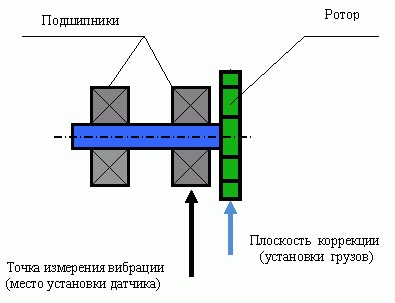
Figure 1 – Selection of the measuring point and correction plane when balancing in one plane.
Figure 2 – Selection of measuring points and correction planes for balancing in two planes in the case of a symmetric rotor (animation: 7 frames, 10 repetitions, 69 kilobytes).
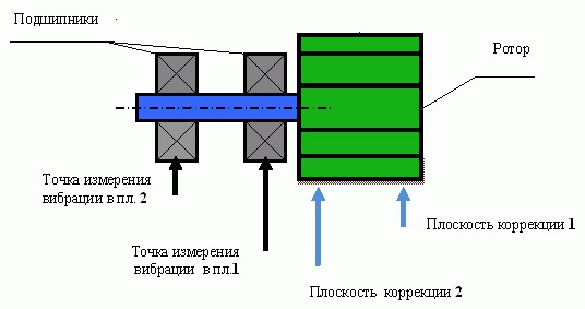
Figure 3 – Selection of measurement points and correction planes when balancing in two planes in the case of a cantilever rotor.
When balancing in two planes, you need to have two measurement points. The correction planes in which the corrective masses are removed (mounted) on the rotor should be selected as close as possible to the measurement points. In the case of balancing in two correction planes, the distance between the planes should be the largest. [10 ]
Conclusions
The master's work is devoted to the study of methods of balancing rotary machines and substantiating their use for the equipment of chemical enterprises. When writing this essay, the master's work is not yet complete. Final completion: June 2018. The full text of the work and materials on the topic can be obtained from the author or his supervisor after the specified date.
List of sources.
- Ширман А.Р., Соловьев А.Д. Практическая вибродиагностика и мониторинг состояния механического оборудования. – Москва, 1996. – 276 с.
- Левит М.Е., Рыженков В.М. Балансировка деталей и узлов. – М.: Машиностроение, 1986. – 248 с.
- Основы балансировочной техники. Том 1,2. Под ред. В.А. Щепетильникова. – М.: Машиностроение, 1975.
- Справочник по балансировке / Под общей редакцией М.Е. Левита. – М.: Машиностроение, 1992. – 464 с.
- Гольдин А.С. Вибрация роторных машин: 2-е изд. исправл. – М.: Машиностроение, 2000. – 344 с.
- Динамика и балансировка гибких роторов. Под ред. А.А. Гусаров - М.: Наука, 1990 — 152 с.
- Вибрации в технике: Справочник. В 6-ти т. / Ред. совет: В.Н. Челомей (председатель). – М.: Машиностроение, 1981. – Т.6. Защита от вибрации и ударов / Под ред. К.В. Фролова, 1981. – 456 с.
- Спектральная вибродиагностика .В.А.Русов Русов – 1996.
- Кравченко В.М., Сидоров В.А., Седуш В.Я. Технічне діагностування механічного обладнання: підручник. – Донецьк: ТОВ "Юго-Восток, Лтд", 2007. – 447 с
- Балансировка роторов. Методическое пособие. В.К. Ковалев – 2016