Abstract
Content
- Introduction
- 1.Theme urgency
- 2.Control Object
- 3.The rationale for choosing a method
- Conclusions
- References
Introduction
Methane is contained in various forms (from free to bound) in coal and enclosing rocks and was formed there at the stage of coalification of organic remains and metamorphization of coals. In production, methane is released mainly from coal (there are deposits where the relative methane evolution [1] exceeds 45 m3 of methane per ton of coal, methane emissions of about 100 m3 / t have also been noted), mainly in the process of its destruction (tearing), less often – from natural reservoir cavities.
1. Actuality of the theme
Methane – a combustible gas without color, smell and taste, lighter than air (density 0.524). It is released during the decomposition of organic substances without access to oxygen. Especially large its emissions are observed in coal mines, smaller – in potash. A mixture of methane and air ignites at a temperature of about 600 ° C. At its concentration in the air up to 5% burns with a blue flame, at a concentration of 5–16% it explodes, with a larger concentration due to lack of oxygen does not burn and does not explode. In the explosion of methane, a large energy is released, the temperature reaches 2500 ° C, the resulting shock air wave causes large damage in the excavations.
The maximum allowable concentration of methane in the jet emanating from the faces is 1%, and in the general mine outgoing jet is 0.75%. Methane weakly poison, but at a high content displaces oxygen. The ignition temperature of methane is 650–750? C, it varies depending on the source of ignition. The peculiarity is that, in contact with the source of ignition, the meta ignites with some delay. At 650 in 10 seconds, 1000 – 1sec, 1200 – 0.2sec, 2000 – instantly. Methane explodes at a concentration of 5 to 16% and at 650 ° C. Causes: poor ventilation, incorrect air distribution. Therefore, it becomes necessary to control these very important parameters within acceptable limits for the sake of safety of human lives and the whole mountain range.
2. Object of control
As an object of control – the concentration of methane at the outlet of the vent and its control in order to prevent explosive concentrations. We set the upper concentration limit of the CH4 content in the substandard methane–air mixture CH4 phlegmatized by combustion products, CH4 30%, and lower – CH4 18%, with the off–grade methane of the air mixture CH4 with the CH4 content in it lower than the established lower concentration limit is diluted with a vent stream to a value of CH4 in a mixture of not more than 4%
3. Justification of the choice of method
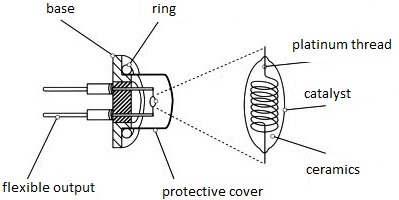
The thermal catalytic sensors, due to the simplicity of their design, are an economically viable solution for the control of leaks of flammable vapors and gases. Structurally, the thermal catalytic sensor is a pair of sensitive elements – balls made of a thin platinum wire wound into a coil, on which a ceramic substrate, for example, made of alumina, is applied (Fig. 1). Distinguished active and passive balls or, as they are also called, pellistor (pellistor) or sygistor (siegistor). On the surface of the active pellistor over the ceramic substrate, in addition, a coating of outer shell of a palladium or rhodium catalyst sprayed onto a substrate of thorium oxide.

Figure 1. Generalized block diagram for DSB.
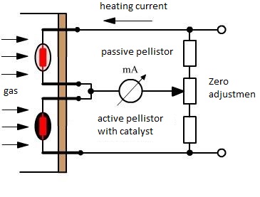
The platinum coils of the pellistors are heated by the current flowing through them to about 450 ° C during operation. Through the gas–permeable membrane (flame arrester, synth metal disk) of the sensor, the combustible gas mixed with air gets inside the sensor and flushes the surface of the sensor's pellistors. The catalytic coating of the active pellistor is oxidized and the temperature of the active pellistor is increased. This increase in temperature can be measured thanks to change (increase) in the resistance of the platinum helix inside the active pellistor. This resistance is compared with the resistance of a passive pellistor in a standard circuit with a measuring bridge (Figure 2).

Figure 2. Foil converter
In the range of concentrations of flammable gas from 0 to 100% of the lower explosive limit (LEL), the ratio of these resistances will be proportional to the gas concentration and can be displayed on a measuring instrument or indicator.
The temperature of a passive pellistor, under unchanged environmental conditions,depends only on the amount of current flowing through it, and the temperature of the active pellistor is determined by the value of the same current flowing through it, plus catalyst oxidation processes whose intensity is proportional to the concentration of combustible gases in the air.
In order for the thermocatalytic sensor to be indepen– dent from the change in environmental conditions (temperature, humidity) in the best catalytic sensors are used thermally matched balls.
In this case, the sensor actually has two active pellistors, one of which acts as a passive pellistor. Passive operation is achieved either by covering the ball with a thin layer of glass, or by deactivated catalyst, or by placing a "passive" pellistor in a practically sealed cavity having only one very small aperture to communicate with the environment.
Thus, the "passive" pellistor acts only as a compensator for any external changes in temperature and humidity. This technology is used, for example, in thermocatalytic sensors DragerSensor PR M DD, where the abbreviation DD stands for a double detector .
Considering that the principle of action of a thermocatalytic sensor is based on combustion of combustible gases contained in the air, then to ensure safe operation, the thermocatalytic sensor must have a strong metal casing, and a flame arrester must be installed in front of the pellistors. This allows the gas and air mixture to penetrate the sensor housing to the sensor element, but prevents the flame from spreading from the sensor to the environment.
The flame arrester somewhat increases the response time of the sensor, however, in most cases, the readings appear a few seconds after detection gas. Since the increase in the sensor reading is significantly slowed down as the measured concentration of the combustible gas approaches its actual value, the response time of the sensor is often defined as the time required to reach 90% of its final reading and therefore known as the T90 value. The value of T90 for catalytic sensors is usually 10 to 30 seconds, that is, they have a sufficiently short response time. In the United States and some other countries, when specifying the characteristics of sensors, the time T60, rather than T90, is often indicated. This fact should be taken into account when comparing the performance of various sensors (Fig. 4).

Figure 4. Variants for installing sensors for an airborne weighing system.
References
- Ермоленко А.П. Автоматизация и электрика [Электронный ресурс]: принцип работы тензодатчика веса и давления – электронные данные, – режим доступа https://www.asutpp.ru/datchiki/tenzodatchik.html – дата доступа: ноябрь 2017
- Я. И. Альшиц, Аппаратура и методы исследования горных машин: Учебник/ Я. И. Альшиц, В. Г. Гуляев, Ф. В. Костюкевич, Е. Г. Колесников, Б. А. Кузнецов, В. И. Лебеденко, В. Д. Оглоблин, П. А. Осокин, В. М. Филиппов, Г. В. Малеев. – Издательство Недра Москва 1969г. С. 19 – 32
- Э.К. Никулин Методология расчётов гидродинамических параметров шахтних автоматизированных стационарных установок с центробежными нагнетателями: монография / Э.К. Никулин,И.В. Ковалёва и др. – Донецк: ООО «Технопарк ДонГТУ «УНИТЕХ», 2015.– 134 с
- Тензом [Электронный ресурс]: Весы на борту транспортного средства – большая экономия и новые возможности для грузоперевозчиков – электронные данные, – режим доступа https://www.tenso-m.ru/publications/349/ – дата доступа: октябрь 2017.
- Соколов А.В., Волков Е.А. Студенческий научный форум [Электронный ресурс]: Бортовые системы взвешивания. Онлайн-контроль массы груза – электронные данные, – режим доступаhttps://www.scienceforum.ru/2015/909/8070 – дата доступа: октябрь 2017
- TOPNEFTEGAZ Топнефтегаз [Электронный ресурс]: Бортовые системы для авто – какую выбрать? – электронные данные, – режим доступа http://topneftegaz.ru/news/view/107356 – дата доступа: октябрь 2017
- Тензом [Электронный ресурс]: Взвешивание на борту – электронный ресурс, – режим доступа https://www.tenso-m.ru/otraslevye-reshenija/vzveshivanie-na-bortu/ – дата доступа: октябрь 2017
- Калмыков С. Основные средства [Электронный ресурс]: Онлайн-контроль массы груза. Бортовые системы взвешивания и контроля перегруза – электронные данные, – режим доступаhttps://os1.ru/article/7343-bortovye-sistemy-vzveshivaniya-i-kontrolya-peregruza-onlayn-kontrol-massy-gruza – дата доступа: октябрь 2017
- Auto Tuning Group LTD [Электронный ресурс]: Бортовые системы взвешивания – электронные данные, – режим доступа http://autotuninggroup.ru/category/bortovye-sistemy/ – дата доступа: октябрь 2017
- Геостар Трейд, СИСТЕМЫ АВТОМАТИЧЕСКОГО УПРАВЛЕНИЯ PROLEC ИТС Интертехснаб [Электронный ресурс]: Технические особенности системы взвешивания для погрузчика экскаватора бортовой системы взвешивания – электронные данные, – режим доступаhttp://vesy.by/preimuschestva-osobennosti-sistemyi-vzveshivaniya-dlya-pogruzchika-ekskavatora.html – дата доступа: октябрь 2017
- Весы-онлайн [Электронный ресурс]: Контроль за перегрузом автомобилей – электронные данные, – режим доступа http://www.onlinescales.ru/articles/publikacii/vzveshennye-resheniya-3/ – дата доступа: октябрь 2017
- PROLEC Research & Development Group LTD [Электронный ресурс]: Бортовые системы взвешивания – электронные данные, – режим доступа http://rdgroupltd.com/projects/cargo/ – дата доступа: октябрь 2017
- ГеоСтар трейд [Электронный ресурс]: системы взвешивания для погрузчиков и шарнирно-сочлененных автомобильных самосвалов – электронные данные, – режим доступа http://geostar.com.ua/products/sistemy-avtomaticheskogo-upravleniya-prolec/weighloader-sistemy-vzveshivaniya-dlya-pogruzchikov-i-sharnirno-sochlenennyx-avtomobilnyx-samosvalov – дата доступа: ноябрь 2017
- Новый дом [Электронный ресурс]: Бортовые системы взвешивания – электронные данные, – режим доступаhttp://newdom.com.ua/p39797-Weighloader_Bortovaya_sistema_vzveshivaniya – дата доступа: ноябрь 2017
- Autoline [Электронный ресурс]: Как работают бортовые системы взвешивания и контроля нагрузки на ось – электронные данные, – режим доступаhttp://truck-weigh.com/how/ – дата доступа: ноябрь 2017
- Michael:P ALM-UG [Электронный ресурс]: Как работает бортовая системы взвешивания – электронные данные, – режим доступаhttp://alm-ug.ru/howw.html – дата доступа: ноябрь 2017
- Сенянский М.В Тензом [Электронный ресурс]: Методологические особенности поосного взвешивания автомобилей – электронные данные, – режим доступа https://www.tenso-m.ru/publications/390/ – дата доступа: ноябрь 2017
- Sensorse [Электронный ресурс]: Фольговые тензорезисторы – электронные данные, – режим доступа https://sensorse.com/page48.html – дата доступа: ноябрь 2017
- DocSlide – PDF библиотека [Электронный ресурс]: Исследование датчика ускорения с использованием четырех лопастной пружины и выбор его оптимальных размеров в рамках поставленной задачи – электронные данные, – режим доступа https://docslide.org/pdf-bgiXrv5 – дата доступа: ноябрь 2017
- Stud 24 электронная библиотека [Электронный ресурс]: Деформационные манометры – электронные данные, – режим доступа http://stud24.ru/polygraphy/deformacionnye-manometry/195408-569829-page2.html – дата доступа: ноябрь 2017
- Большая энциклопедия нефти и газа [Электронный ресурс]: Сопротивление – резистор – электронные данные, – режим доступа http://www.ngpedia.ru/id457315p1.html – дата доступа: ноябрь 2017
ГОСТ 12.1.005
