Abstract
Contents
- Introduction
- 1. Relevance of the topic
- 2. The purpose and objectives of the study
- 3. Mathematical modeling of the up-pulse converter
- 4. Requirements for control system of boost pulse converter
- 5. Planned research
- References
Introduction
The paper substantiates the possibility of using pulse-width modulation to control the boost pulse converter under different loads. This type of transducer is characterized by non–linear adjustment characteristic, which makes it difficult to use PWM for it.
1. Relevance of the topic
The boost pulse converter (PI) is used in solar power stations and electric vehicles. This fact is based on the fact that the current consumed from a constant current source (battery or solar battery) is continuous. In comparison with the impulse current of the source, the losses are less; besides, the current–voltage characteristic of the solar panel does not, in fact, create a maximum power consumption mode. Also, this source is characterized by a low voltage value, which varies during operation.
Therefore, the task of designing a control system for these applications based on the hardware PWM module of modern microcontrollers is an important task. In this paper, we consider only the operation of a pulse converter for active resistance.
2. The purpose and objectives of the study
The purpose of the master's work is to develop a control system for a boost pulse converter operating on different types of loads.
The main objectives of the study:
- Mathematical modeling of the up-pulse converter.
- Review of the existing control methods of boost pulse converter.
- Description of the hardware module PWM microcontroller STM32F4.
- Development of a boost pulse converter control system based on a PWM hardware module.
3. Mathematical modeling of the up-pulse converter
Checking the adequacy of the models for instantaneous values (Instantaneous model) and for average values (average model) was used for the simulation model in MATLAB collected using the powersystem library (matlab powersystem model).
The general view of the model is shown in Figure 3.1.

Figure 3.1 – General view of the model
The following parameters were used in the simulation: E=4 V, L=1 mH, С=1 mF, R=5 Оhm, RΣ=0.101 Оhm, TPWM=0.1 мс, γ=0.75 (duty cycle PWM), the period of the discreteness of the model 2 μs.
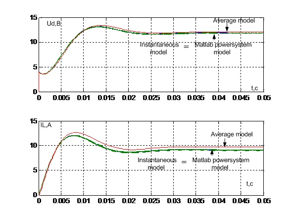
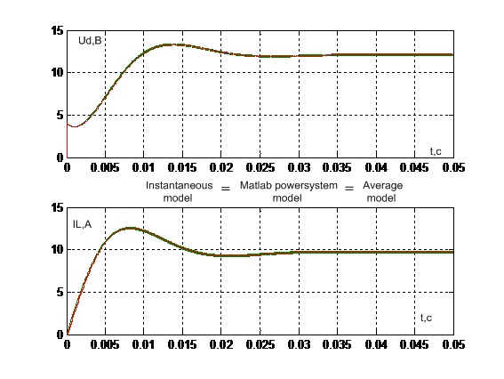
Figure 3.2 shows diagrams of three models in MATLAB. They can be seen that the convergence is within 5 %. However, the error is due to inaccuracy PWM generator, which has a period of 0.1 ms, and in the PWM period only 50 points fit. By reducing the discreteness period to 0.2 μ s, you can get 500 points per PWM period. Results model work is shown in Figure 3.3.
Longer operation intervals of the boost pulse converter in the transient and steady state operation is shown in Figure 3.4. Where it is clear that the convergence of models in transient modes it is one discrete step behind, and in steady state there is no error.
At the same time, the instantaneous model also almost converges with the simulation model (powersystem model).

Figure 3.2 – The results of the models with a discretization step of 2 μ s

Figure 3.3 – The results of the models with a discretization step of 0.2 μ s

Figure 3.4 – Enlarged schedules of the model in transitional and steady–state operation
4. Requirements for control system of boost pulse converter
For the above–described applications of a solar power station and an electric vehicle, a step–up power source should provide control [3–5]:
- Sufficient accuracy in regulating the output voltage.
- To have high speed in voltage regulation.
5. Planned research
It is planned to develop a control system for an up–to–date impulse converter that would enable the use of a PWM hardware module and at the same time satisfy the requirements for a control system.
At the time of writing this essay, the master's work has not yet been completed. Estimated completion date of master's work: June 2019. The full text of the work and materials on the topic can be obtained from the author or his manager after the specified date.
References
- Шавелкин, А. А. Преобразовательная техника – Шавьолкін, О.О. Перетворювальна техніка: учеб. пособие/ А.А. Шавелкин [и др.]. – Краматорск: Донбасская ДМА, 2008. – 328 с.
- Зиновьев, Г. С. Силовая электроника : учебное пособие для бакалавров. [Электронный ресурс]. – Режим доступа: http://ozon-st.cdn.ngenix.net/..
- Патент 2279705 Российская федерация, МПКG05F1/613. Способ питания нагрузки от солнечной батареи / А.И.Чернышев, Ю.М.Казанцев, А.Ф.Лекарев [та ін.]; заявитель и патентообладатель Федеральное государственное унитарное предприятие
Научно–производственный центр
. 2004128060/09; заявл. 20.09.2004; опубл. 10.07.2006, Бюл.№19.Полюс
- Мирошник Д.Н. Усовершенствование системы управления для повышения энергетической эффективности тягового частотно–регулируемого асинхронного электропривода с питанием от аккумуляторной батареи – Мірошник Д.М. Удосконалення системи керування для підвищення енергетичної ефективності тягового частотно–регульованого асинхронного електропривода з живленням від акумуляторної батареї : дис. ... канд. техн. наук : 05.09.03 : защищена 13.12.12 / Д. Н. Мірошник. – Донецк, 2012. – 193с.
- Шавелкин А.А. Преобразователь частоты с импульсным преобразователем в звене постоянного тока / А.А.Шавелкин, Д.Н. Мирошник // Вісник Національного університету
Львівська політехніка
. Серія: Електроенергетичні та електромеханічні системи. – Львів: НУЛьвівська політехніка
. 2003. –№485. – С. 156–163. - Калачев, А. Богатый набор для неординарных задач: возможности DSP в STM32F4 на ядре Cortex–M4. 2012 г. [Электронный ресурс]. – Режим доступа: https://www.compel.ru/.
- STM32 F4 Hi–Performance & DSP. [Электронный ресурс]. – Режим доступа: https://www.st.com/content/st_com/en.html.
- Иванов, Р. Самый производительный микроконтроллер на ядре Cortex-M4/ Р. Иванов, Р. Попов //Компоненты и технологии. 2012. №5. С. 96 – 101.
