
Contents
- Introduction
- 1. Relevance of the topic
- 2. The purpose and objectives of the study, the planned results
- Conclusion
- References
Introduction
A dewatering plant is a complex of technical means for removing water from mine workings and lifting it to the surface. Water drainage of mining enterprises is an important element of the entire complex of mining equipment, and its reliable operation largely determines the continuity and safety of mining operations for the extraction of minerals [1]. Like any other important support system, it requires economically sound technical solutions at the stages of its design and automation.
Mine drainage installation is a complex structure, which includes: a complex of mine workings, pumping units of various capacities, pipe collectors, power supply system and automation equipment. It should provide pumping of water from the mine workings, while possessing high reliability and efficiency. Pumped water after lifting to the surface and subsequent cleaning can be used for technological needs. Drainage is designed with a reserve capacity of the sump and reserve pumping units to ensure the reliability, it provides redundant power supply and duplication of pipelines [2].
Considering the variety of types of drainage and hydrogeological conditions of mines, serial equipment is usually used to automate this process [3].
To increase the efficiency of this equipment, it is advisable to transfer it to a modern element base using computer technology.
1. Relevance of the topic
Drainage systems of mining enterprises, which work out the flooded areas, are a complex energy-mechanical complex, the automation of which is very relevant.
Figure 1 shows the hydraulic scheme of the pump unit when pumping water from the catchment well, where 1 is the suction well; 2 – supply pipe equipped with a receiving grid PS (protecting the pipeline from a solid particles sized greater than 0.3-0.5 width of the impeller exit slot) and a check valve OK (which prevents water from flowing out of the main pump through flow during priming); 3 – pump; 4 – discharge pipeline with check valve OK (used to save water in the discharge pipeline when the pump is stationary, to prevent the backward movement of water when the pumps are stopped and to protect the pump from water hammer when unplanned stop), the adjusting valve of the RR with the PZ drive (used to change operating modes of plant) and limit switches of KVO, KVZ position; Qт – flow meter installed on the supply pipe; hт – level gauge, located in the sump [3].
Figure 1 – Technological scheme of the pumping unit of the mine’s main drainage system (animation: 8 frames, infinite repetition cycle, 8 kilobytes)
The cost-effective and reliable operation of the drainage installation is largely determined by the conditions of the actual operation of the pump to the external network, which are constantly changing during operation due to increased equipment wear during pumping of water with suspensions, acidic water, overgrowth of pipeline network elements, cavitation phenomena. As a result of the cumulative effect of these factors, the operating parameters of the pumping installation change: supply, pressure, efficiency, which in turn leads to excessive energy consumption for pumping [3-5].
The mode of operation of the water treatment plant is influenced by a number of parameters that determine its current state:
- Q – flow of drainage plant;
- H – pressure of drainage plant;
- HВ – vacuum suction height;
- HГ – geodetic discharge height;
- N – power of drainage plant;
- Е – specific energy consumption of water drainage;
- η – efficiency of water drainage;
- QП – hour inflow of mine;
- ρ – fluid density;
- dВ – suction pipe diameter;
- dН – discharge pipe diameter;
- LВ – suction pipe length;
- LН – discharge pipe length;
- αВ – hydraulic resistance of the suction pipe;
- αН – hydraulic resistance of the discharge pipe.
Analysis of the effect of these parameters on the mode of drainage operation shows its ambiguity. Each parameter in a certain way affects the working mode of water drainage, however, three groups of parameters can be distinguished: constant, disturbing, controlled.
Constant parameters remain unchanged or slightly and slowly change during operation. This group of parameters includes such technical characteristics of drainage as dВ, dH, LВ, LH, N, η, HВ, HГ, which define their own dynamic properties of the control object and are used in determining the constants of time and transfer factors of the elements of the drainage plant.
Controlled parameters are such variables, the impact on which allows to obtain the required modes of operation of the control object. For a drainage system these are the following variables: Q, H. As is known, the drainage systems of coal mines are usually equipped with centrifugal sectional pumps. In this case, the controlled parameters Q, H are interrelated. This leads to the fact that when one of the controlled parameters is affected, other controlled parameters will also change. Therefore, it is necessary to take this feature into account when developing the principles of drainage control.
The hour inflow of the mine QП also effects the drainage system.
The operating mode of the drainage plant is graphically determined by the point of intersection of the operating characteristics of the pump and the discharge pipe. The operating parameters of the pumping unit shown in Figure 2 Qр и Hр are the main parameters and are controlled. However, the mode of operation of the drainage plant is determined by all considered parameters.
Point A in Figure 2 indicates the design mode of the pump with the characteristic HН=f(Q) on pressure pipe with characteristic HТ=f(Q). However, in the process of operation, there is a change in the operating mode and its parameters due to the impact of the disturbances considered and under the influence of external conditions. Therefore, we obtain not the working point, but the working area ABCD – Figure 3.
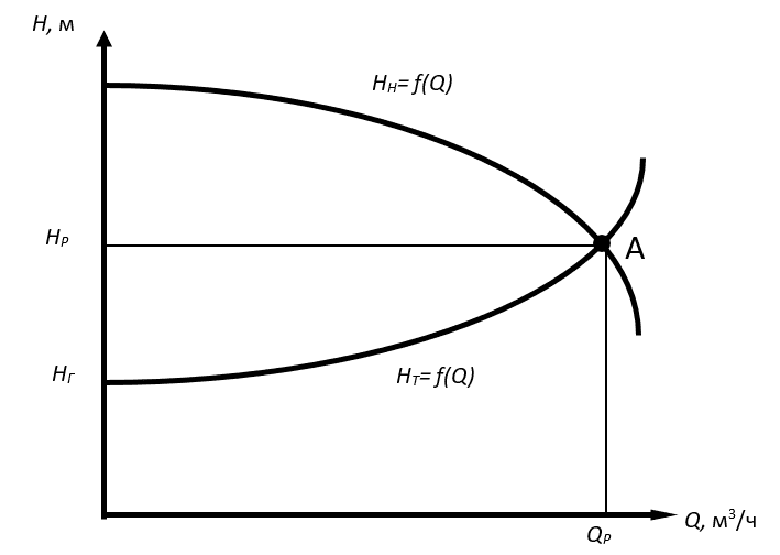
Figure 2 – Operating mode of the drainage plant
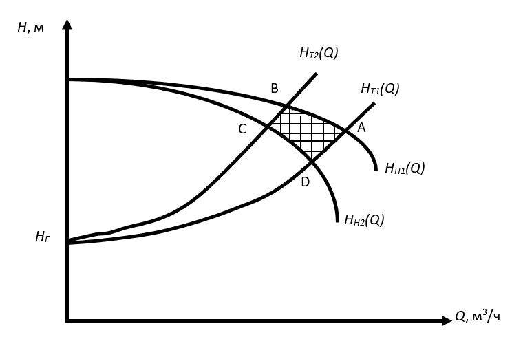
Figure 3 – Working area of the drainage plant
As a result of the analysis of the control object, such major problems were identified that require the design of an automation system, such as: inconsistency in the flow and pressure of the drainage plant; the oscillation of water pressure, the need for direct human intervention to change the setpoint of the existing system of reducing the pressure of water. As a result, these problems resulted in an overspending of electricity, as well as a decrease in the reliability and service life of the drainage plant due to excessive load..
The automatic control system will optimize the processes of maintaining the main technological parameters, increase the reliability of the water-removal plant, reduce the costs of its maintenance and servicing, as well as the expenses for electricity.
2. The purpose and objectives of the study, the planned results
The goal is to ensure the reliability and economical operation of the drainage process, which will eliminate flooding of mine workings and create safe conditions for mining operations.
The main functions performed by the ACS:
- smooth start and stop of the pump with closed valve;
- valve control (to exclude water hammer and pressure surges) when starting and stopping the pump unit;
- automatic activation of the auxiliary work unit when the water reaches the upper level and its continuous operation to the lower level;
- automatic activation of the backup pump unit, if the main pump fails or it cannot cope with the inflow and the water has reached the emergency level;
- emergency stop of the pump with a decrease or loss of flow;
- automatic control of the main technological parameters of the drainage plant – supply, pressure, water levels in the sump;
- ensuring optimum energy consumption.
Conclusion
As an control object was considered the drainage plant of a coal mine.
Analysis of the parameters affecting the operating mode of the drainage plant, allowed to draw up a block diagram of the control object. Angle of rotation of the valve and the frequency of rotation of the drive motor were taken as the control variables. The output parameters are the pressure characteristics of the pump, the pressure characteristics of the pipeline and the power consumed by the drainage.
Using the built-in adjustment tools of the Matlab Simulink package, the coefficients of PI and PID controllers were calculated. The quality of the transition process with the use of such regulators completely satisfies the user due to the absence of static error and overshoot.
When writing this essay, the master's work is not completed yet. Final Completion: June 2019. The full text of the work and materials on the topic can be obtained from the author or his supervisor after that date.
References
- Гейер В.Г., Тимошенко Г.М. Шахтные вентиляторные и водоотливные установки. / В. Гейер, Г. Тимошенко. – М.: Недра, 1987.– 270 с.
- Попов В.М. Рудничные водоотливные установки. – 2-е изд., перераб. и доп. / Попов В.М. – М.: Недра, 1983. – 304 с.
- Иванова А.А. Автоматизация процессов подземных горных работ. Под общей ред. / Иванова А.А. – Киев; Донецк: Вища шк., 1987. – 327 с.
- Толпежников Л.И. Автоматическое управление процессами шахт и рудников: Учебное пособие для вузов. – 2-е изд., перераб. и доп. / Толпежников Л.И. – М.: Недра, 1985. – 352 с.
- Гаврилов П.Д. Автоматизация производственных процессов. Учебник для вузов. / Гаврилов П.Д., Гимельштейн Л.Я., Медведев А.Е. – М.: Недра, 1985. – 215 с.
- Тимошенко Г.М. Научные основы проектирования и эксплуатации насосных установок в переходных режимах. / Тимошенко Г.М. – Киев; Донецк: Вища шк. Головное изд-во, 1986.– 127 с.
- Денисенко В. В. ПИД-регуляторы вопросы реализации часть 2 / Денисенко В. В. – М.: СТА 2008. № 1. с 86-99
- Зайцев Г.Ф. Теория автоматического управления и регулирования. / Зайцев Г.Ф. – Киев: Вища школа, 1988 – 431 с.
- Лукас В. А. Теория автоматического управления. / Лукас В. А. – М.: Недра, 1990. – 416 с.
- Дорф Р., Бишоп Р. Современные системы управления. / Р. Дорф, Р. Бишоп – М.: Лаборатория Базовых знаний – 2002 – 832 с.