
Summary of the final work
Content
- Introduction
- 1. Relevance of the topic
- 2. The purpose and objectives of the study
- 3. Modeling the process of stamping wheel blanks on presses with a force of 20 MN, 50MN, 100MN
- Conclusions
- List of sources
Introduction
Relevant to the modern theory of wheel-rolling production is the creation of methods for designing technology to deform accurate by weight (the difference of blanks by weight up to 1%) wheel blanks, which would provide a high accuracy of the prediction of metal shaping and power parameters of the processes of stamping and rolling blanks. The solution of this problem requires a change in the formulation of the relevant boundary-value problems and methods for their implementation in accordance with the technical and technological features of production. Wheels on a specific press-rolling line.
Setting the task of modeling. In the present work, the problem of modeling the multi-transition process of deforming wheel blanks with its subsequent implementation in the system is set DEFORM 3D.
1. Relevance of the topic
The actual direction of improving the technology of deformation of wheel blanks on the press-rolling line is the creation of technological schemes and modes of deformation of the metal, allowing to reduce the asymmetry of the forged wheel blanks and, as a result, reduce the eccentricity of the rolled wheels.
The equipment of the press-rolling line, put into operation more than 40 years ago, on the one hand, allows to provide high performance of technological process, and, on the other hand, is morally obsolete, resulting in instability of the sizes of pressed-rolled wheels and increased repair turning.
2. The purpose and objectives of the study
This paper is devoted to modeling the process of stamping a billet using a new method of stamping with partially formed rim and hub on a billet press.
The disadvantage of the existing technology is the unsatisfactory centering of the workpiece before it is formed in the press dies of 100 MN. Existing center pressrequires constant adjustment in the course of work, which is not always done, since for this it is necessary to stop the rental. As a result of this, at a high rolling rate, a large number of rolled wheels with unstable rim sizes are obtained and, as a result, increased repair turning.
The advantage of the new technology: the resulting billet will be self-centered in the lower press of the 100MN press even before the deformation begins on the formed seating surface in the hub area.
The application of the proposed technology will allow stabilizing the dimensions of the wheel blanks and, accordingly, the wheels rolled from them.
To study the features of the considered technology, it is necessary to perform in the DEFORM 3D system a finite-element simulation of the process of upsetting the billets.
3. Modeling the process of stamping wheel blanks on presses with a force of 20 MN, 50MN, 100MN
A preliminary draft on a 20 MN press is made in order to reduce the height and increase the cross-sectional area of the blanks. The precipitate is used to improve the structure and mechanical properties of metal billets, as well as to reduce the unevenness of properties in the axial and radial directions.
In the process of precipitation, the scale is removed from the side surfaces of the blanks, as well as the scale that remained after water jetting from the end surfaces. Press force of 20 MN - hydraulic vertical four-column with an architrave and a bed installed on the foundation. Between the bed and architrave located traverse, which moves through the columns of the press. A plate is installed on the base of the press and the support, along the guides of which the press table moves. The plate rests on one side of the bed frame, and on the other it is supported by two hydraulic cylinders, under constant pressure.
The traverse is lowered by the plunger of the working cylinder, the traverse is raised by two lifting cylinders placed in the tides of the architrave. Sedimentary plates are attached to the traverse and the table.
The working cycle of the press consists of lowering the traverse to contact with the workpiece, the working stroke - precipitation of the workpiece and lifting the traverse to its original position. The lowering of the traverse begins after the manipulator supplies the workpiece to the press table during its return to the initial position. Set value of precipitation Provided by the automatic traverse control system. To control the height of the upset billet, the press is equipped with a traverse pointer in the form of a dial with a rotating arrow. The thickness variation of the upset blanks should not exceed 2 mm.[1]
Before serving the workpiece to the press table, dispensing process is applied to the middle of the lower compression plate in order to prevent the pressing of the scale, not separated after water jet. It is also fed to the upper end surface of the workpiece.
After precipitation, the billet is removed by the manipulator from the working area of the press with a force of 20 MN. To prevent heating and reduce wear, the crimp plates are cooled with water after removal of the billet. Scale from the bottom plate is also removed with water.
On the roller table, the billet is fed to a tilter installed in front of a 50 MN press and edged by 180 °. For a more complete removal of secondary scale, the end surface of the workpiece before tilter and after it are cleaned with metal brushes, after which the billet on the roller table is fed to the press with a force of 50 MN. Preparation on the press 50MN before a distillation - centered (by lifting the ring). The deformation operations on the press with a force of 50 MN are carried out with a view to the regulated distribution of metal between the peripheral and central parts of the workpiece.[2]
A press with a force of 50 MN - a hydraulic vertical four-column consists of fixed crossbeams - a bed and an architrave, connected by columns. With a press force of 50 MN billet cleaning the transfer machine is moved to the discharge roller table and transported to the molding press with a force of 100 MN. At the same time, it is subjected to descaling with metal brushes.
The deformation of the workpiece on a press with a force of 100 MN is performed in order to obtain a molded workpiece with the final dimensions of the hub and the adjacent part of the disk, as well as the preparation of the rim and the adjacent part of the disk for subsequent rolling on the wheel-rolling mill.
The press with a force of 100 MN - a hydraulic vertical four-column one has two fixed cross-beams - a bed and an architrave, connected by four columns. The worker is installed in the architrave press cylinder, as well as two lifting differential and two balancing cylinders. The plungers of these cylinders are mounted on a movable traverse. The cross-plate is attached to the traverse, in which the upper ejector of the workpiece is installed. The ejector cylinder works in conjunction with lifting traverse cylinders.[2]
The technological cycle of the operation of the press with a force of 100 MN includes the following operations: laying the workpiece on the lower forming die; centering the workpiece on the stamp; lowering the traverse to the contact of the upper stamp with the workpiece; working stroke - forming billet; lifting traverse to its original position; removing the molded workpiece with ejector from the upper and lower punch and issuing it on the roller table.
Simulation results At the first stage of research, the process of cooling the billet in the air during its transportation was carried out (transportation time - 25 s) on the roller table from the furnace to the sedimentary press with a force of 20 MN. The temperature distribution in the billet after its transportation and holding (exposure time –5 s) on the bottom plate of the 20MN press is shown in Fig. 3.1. The average temperature of the metal on the surface of the workpiece before the draft is 1260 - 1270 ° C. The free draft of the workpiece is produced to a height of 117–120 mm. The results of the simulation of the draft precipitation process, are presented on fig. 3.2. The obtained precipitation strength (24.9MN) is the maximum possible for this press. It is reached at the pressure of the working fluid. 31,4МН/м2.[3][4][5]
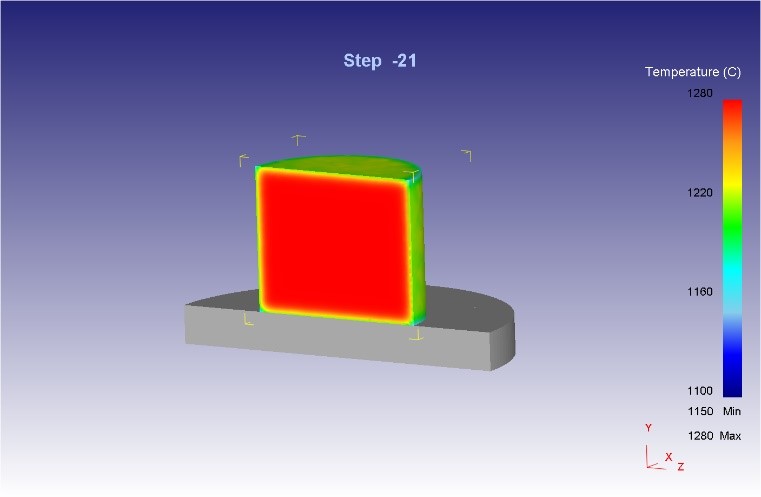
Picture 3.1 – Preparation after its transportation and endurance on the bottom plate
After that, the billet is fed to a press with a force of 50 MN (transport time - 10 s) for a sediment-distillation in the process ring. Before the 50 MN press, the billet is turned 180 ° to level temperatures from its upper and lower sides. In fig. 3.3 a, b show the temperature distribution in the workpiece before and after its transportation to the 50 MN press, as well as after holding the workpiece. (dwell time - 5 s) on the lower press plate of the press. The average temperature of the metal on the surface of the workpiece before distillation is 1250 – 1260°С.
Picture 3.2 – The workpiece after its precipitation on the press force of 20 MN
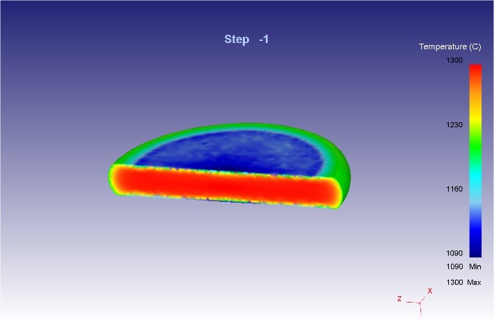
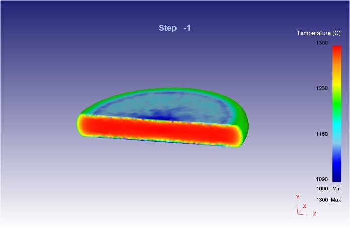
Picture 3.3 – Harvesting (a) before and (b) after it is transported and aged on the bottom plate
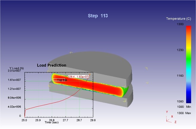
At the next stage, lowering the traverse of the press is performed before the contact of the upper stamp with the workpiece occurs. The results of the simulation process before and after the workpiece distillation on a press with a force of 50 MN are presented on fig. 3.4 a, b.
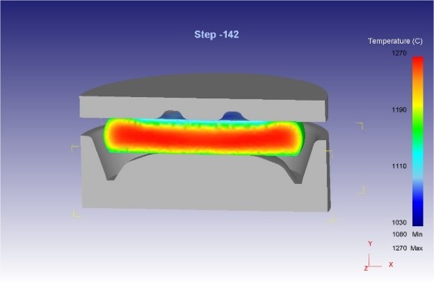
Picture 3.4 – Harvesting (a) before and (b) after its distillation on a press with a force of 50 MN
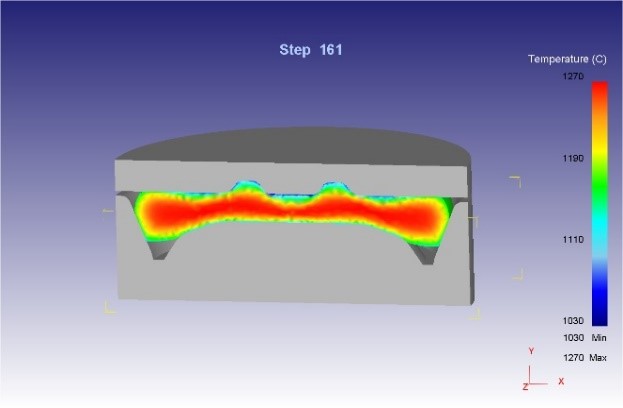
After distillation on the press 50MN, the billet is transferred to the press with a force of 100MN, where molding is carried out. Such a blank is self-centered in the lower die, which ensures the stability of the process. In fig. 3.5 a, b, presents the results before and after molding.
Conclusions
A scheme for stamping wheeled blanks has been developed, which provides increased accuracy and dimensional stability of the resulting blanks for rolling.
Due to the formed caliber on the billet press 50MN, the billet will be self-centered in the lower die of the molding press 100MN, which will ensure the stability of the process.
The analysis of the shaping and power parameters of the processes of deformation of billets on presses 20MN, 50MN and 100MN showed the rationality of the developed deformation modes.
The values of the forming forces, the temperatures of the workpieces and the parameters of their shaping were obtained in the simulation are in good agreement with the experimental data obtained in the conditions of industrial production of wheels with a diameter of 957 mm.
List of sources
- Yakovchenko, A.V. Designing profiles and calibrations of railway wheels: monograph / A.V. Yakovchenko, N.I. Ivlev, R.A. Golyshkov. - Donetsk: DonNTU, 2008. - 491с.
- Yakovchenko A.V., Snitko S.A., Ivleva N.I. Ways to improve computer programs for designing calibrations of deformation tools for the production of extruded-rolled railway wheels // Metal and casting of Ukraine. - 2003. - № 6. - p. 30-35.
- Gong G.Ya. Theoretical bases of metal processing pressure / G.Ya. Gun - M .: Metallurgy, 1980. - 456 pp., Ill.
- Snitko S.A. Analysis of power and speed parameters of rolling wheels / S.А. Snitko // Naukov Pratsi DonNTU. Metalurgy: Zb. sciences. pr. - Donetsk, 2008. - Vip. 10 (141). - p. 163 - 172.
- Prediction and method of eliminating the formation of clamps when forming wheeled blanks / B.G. Kaplunov, V.N. Krashevich, M.I. Staroseletsky, A.V. Belushchenko // Izv. universities Ferrous metallurgy. - 1991. - № 1. - p. 55–56.
- Shifrin M.Yu. Reserves of productivity and yield when rolling wheels / M.Yu. Shifrin. - M .: Metallurgy, 1989. - 144 pp., Ill.
- Shifrin M.Yu. Rational mode of precipitation of wheel rim / M.Yu. Shifrin // Steel. - 1993. - № 5. - p. 52–54.