
Abstract
Content
- Introduction
- 1. Finite element modeling of wheel blanks stamping schemes
- 2. Research results
- Conclusion
- References
Introduction
Many of the tasks that researchers and engineers currently face are either not amenable to analytical solutions or require huge costs for experimental implementation. Often, the only possibility of express analysis of an engineering problem is computer-aided mathematical modeling. Progress in the development of numerical methods has significantly expanded the range of tasks available for analysis. The results obtained on the basis of these methods are used in almost all areas of science and technology.
A modern technological process, including metallurgical, cannot do without the active use of both computer equipment and the appropriate software necessary for developing and mastering new technologies and, of course, to meet the needs of current production (development of drawings, design documentation, performing verification calculations, etc.).
1. Finite element modeling of wheel blanks stamping schemes
To date, the actual scientific and technical challenge in the production of railway wheels is the improvement of stamping schemes in terms of the application of rational power modes of operation of presses and high resistance of the deformation tool.
In this work, we will consider 3 schemes for stamping railway wheels: developed by SMS Eumuco specialists, specialists of Evraz NTMK, JSC and employees of Vyksa Steel Works (hereinafter referred to as VSW), which were implemented at the enterprises of Evraz NTMK and JSC VMZ.
Along with obtaining the required parameters for geometry, macro- and microstructure, as well as mechanical properties of products, one of the important criteria for evaluating the effectiveness of the used billet deformation schemes is their influence on the press-equipment power mode and durability of the deforming dies.
In wheel-rolling production, an increase in tool life of the deformation tool is an urgent task, since it is this parameter that affects the costs associated with the choice of steel grade for dies, the scheme of their production and the technological lubricant used.
The purpose of this work is to study the effect of the above-mentioned punching patterns on the power parameters of the molding press R9000 and the press with a force of 100 MN and the amount of deformation tool wear (data stamps of the presses).
The analysis of metal forming, temperature and power parameters, as well as die wear on the molding presses R9000 and 100 MN was performed based on the results of the finite element modeling of the stamping process in the DEFORM-3D environment.
A plastic model of the material was chosen for the wheel billet; the metal flow curves were calculated for steel grade T (GOST 10791-2011) for the SMS Eumuco technology, Evraz NTMK JSC and VMZ JSC.
The billet had an uneven temperature field in the range of 1100-1280°C, obtained by finite-element modeling of the transportation of the billet to the R5000 press, deformation of the billet on this press and transportation to the R9000 press for the SMS Eumuco technology and Evraz NTMK. For VSW technology, the temperature of the workpiece was 1080–1260°C, which was achieved by simulating the transportation of the workpiece to a sedimentary press of 20 MN, deformation on the press of 20 MN, transport to the press of 50 MN, deformation on this press and transport to the press 100 MN.
It is not possible to get the actual values of the tool wear value due to the lack of information for calculating this parameter using the tools embedded in the DEFORM-3D program, then only a comparative analysis of the wear value of the dies is possible with respect to several technologies.
In the comparative evaluation of various patterns of forming wheel blanks only abrasive wear was taken into account. To calculate the amount of wear used model Archard.
Contact friction voltage was determined as a fraction of the magnitude of the voltage of the metal flow in shear.
2. Research results
The analysis of three schemes of stamping wheel set (figure 1-3) for wheels with a diameter of 957 mm with a flat-bottom disk according to GOST 10791-2011 was performed:
- Punching scheme with pre-draft by smooth plates of wheeled blanks in the upper floating calibration ring (this technology is currently used on the press-rolling line of Evraz NTMK OJSC;
- A punching scheme with pre-forming a blank on the R5000 press (this technology was developed by SMS Eumuco and introduced at the Evraz NTMK enterprise);
- A punching scheme with pre-draft of the workpiece on smooth press plates with a force of 20 MN and “distillation” in the lower technological ring at a subsequent press with a force of 50 MN (the technology is used at the enterprise of Vyksa Metallurgical Plant).
The simulation results showed that when stamping wheeled blanks in all three schemes, the temperature of the stamps at the last moment of the stamping does not exceed 300°C.
As a result of the analysis, it was found that when stamping the wheel blank according to scheme 1, the dies in the hub area are filled long before the end of the molding process (figure 1b), which implies the operation of the press under extreme conditions with the maximum allowable forming force. As a result of this, in some cases, there is under-stamping of the wheel blank due to the fact that the force required to continue deforming the metal, even taking into account the work of the press in the mode of holding under load, exceeds the permissible value (90 MN). In addition, the de-stamping of the wheel blank in the holding mode, the maximum force developed by the press for 2-4 seconds, leads to an increase in the contact time of the deformable metal with the tool and, therefore, to its additional heating, which reduces the service life of the deforming dies.
When stamping wheel blanks according to schemes 2 and 3, the power mode of the press is more rational, because in this case, the average force value for forming conditions is less than 25% of the corresponding average force value when stamped according to scheme 1) and is characterized by a gradual increase in the force required for the realization of the molding process, as can be seen in the graphs (figure 2b; 3b). Its maximum value is needed only at the last, short moment of stamping (figure 2c; 3c). At the same time, the operation of the press R9000 and the press with a force of 100 MN in the mode of holding under load, as when stamping according to scheme 1, is not required.
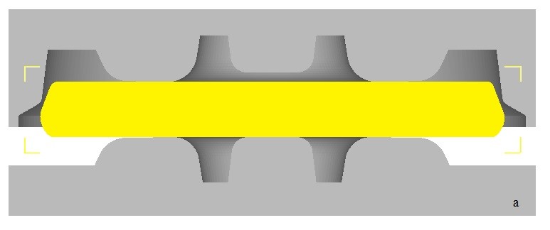
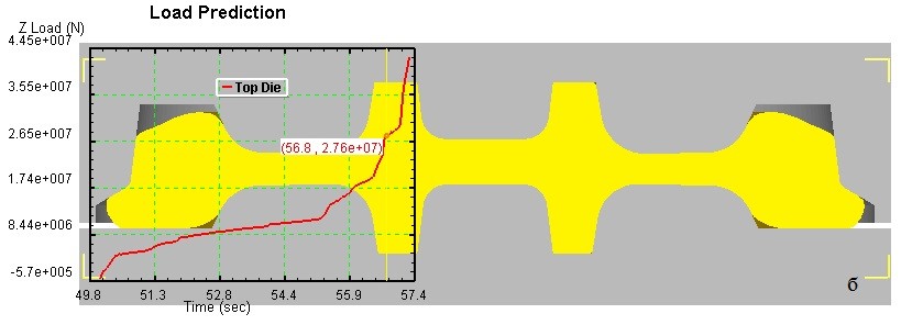
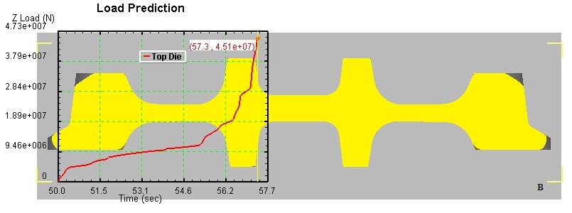
Figure 1 - Punching wheeled blanks according to scheme 1: a - the first moment of time; б - intermediate moment of stamping; в - the last moment of stamping.
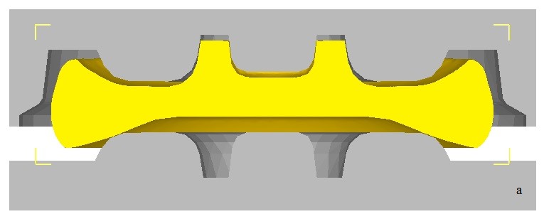
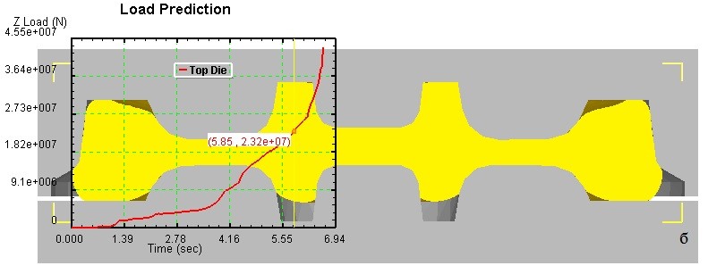
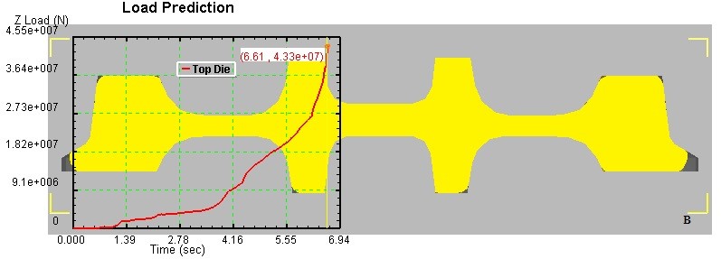
Figure 2 - Punching wheeled blanks according to scheme 2: a - the first moment of time; б - intermediate moment of stamping; в - the last moment of stamping.
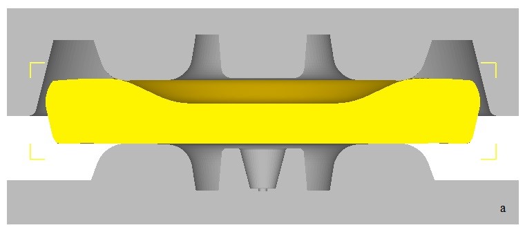
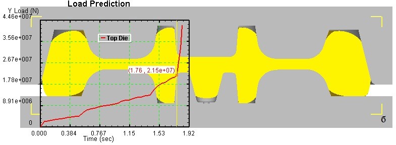
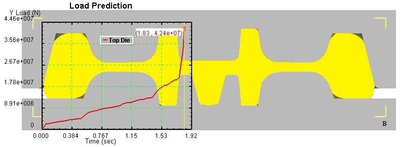
Figure 3 - Punching wheeled blanks according to scheme 3: a - the first moment of time; б - intermediate moment of stamping; в - the last moment of stamping.
Based on the simulation results of the deformation tool wear process (figure 4-6), we can formulate the following conclusions: the premature filling of the hub (scheme 1) and the implementation of the one-way metal flow scheme at the final stage of molding leads to an increase in the wear value of the forming dies by more than 30% (relative to other schemes) in the area of the formation of the disk wheel set, because it is in this part that the main deformation of the metal occurs; the implementation of the preform “pre-distillation” molding scheme (scheme 3), in addition to reducing wear (relative to scheme 1), leads to localization of die wear from the disk forming section to the transition section from the disc to the hub and the transition section from the disc to the rim, and in the second in the case of this value is 2 times greater than in the first; implementation of the blank forming scheme with preforming the upper part of the blank (scheme 2) even more reduces the amount of wear of the deformation tool, relative to the two previous schemes, and at the same time the main wear falls on the transition section from the disk to the rim. The wear of the deforming dies due to the premature contact of the edges of the billet with the forming ring, although it is present and practically equal for all three schemes, however, is insignificant compared to the basic amount of wear.
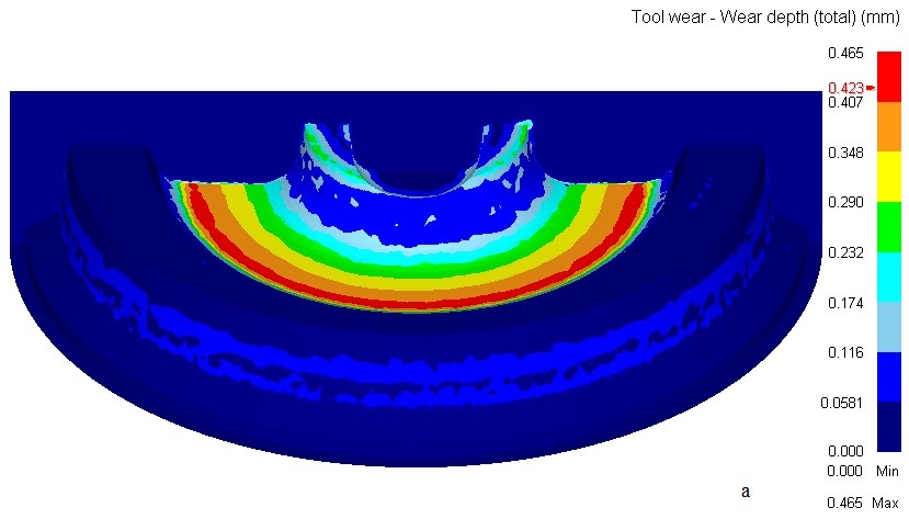
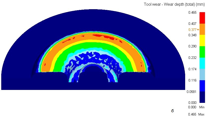
Figure 4 - Results of modeling the wear of dies when stamping the wheel blank according to scheme 1: a - upper stamp; b - bottom stamp
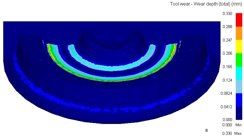
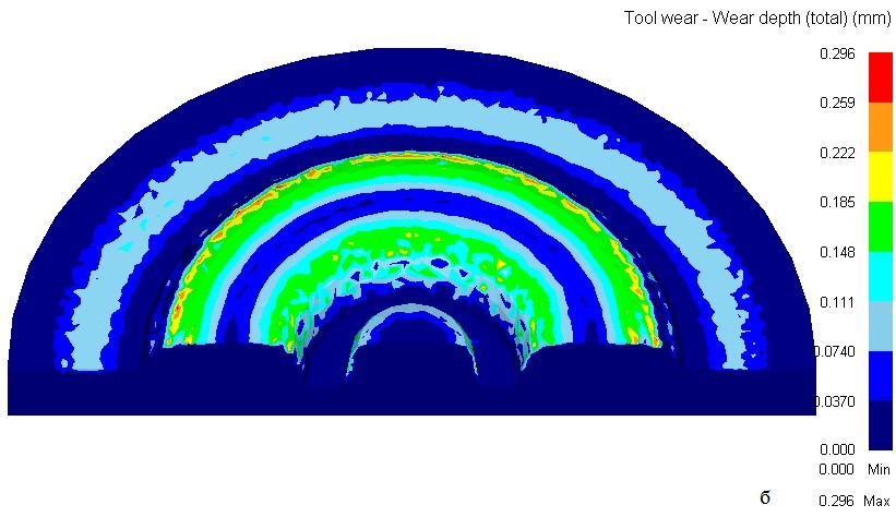
Figure 5 - Results of modeling the wear of dies when stamping the wheel blank according to scheme 2: a - upper stamp; b - bottom stamp
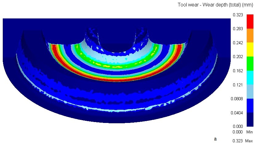
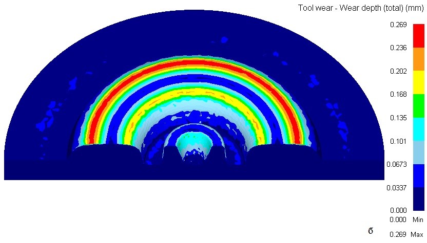
Figure 6 - Results of modeling the wear of dies when stamping the wheel blank according to scheme 3: a - upper stamp; b - bottom stamp
Conclusion
Thus, on the basis of the results of the finite element modeling, the analysis of the effect of the forging schemes of wheel blanks on the power modes of operation of the molding press and the wear of the deformation tool has been analyzed.
It is shown that the use of stamping schemes, which provide for a regulated distribution of metal between its central and peripheral parts, is characterized by a rational power mode. First, the value of the average force in this case decreases by 25% from the value of the average force when stamping according to scheme 1. Secondly, in this case there is a gradual increase in the force necessary for the realization of the molding process, and its maximum value is necessary only in the last, short time stamping.
The exception of premature filling of the hub and, accordingly, one-sided flow of the metal at the final stage of forming contributes to reducing the average amount of wear of the forming dies by more than 30%. It was established that in the process of metal compression in the disk area, the earlier the metal flow is formed from the side of the forming ring, the smaller the amount of slippage of the deformable metal relative to the surface of the forming dies in the zones of their most intense wear (transition from disk to rim) and, as a result, less wear.
References
- Снитко С.А., Дужуржи А.А. Влияние параметров конечно-элементных моделей на точность расчета формоизменения металла и сил при штамповке и прокатке заготовок железнодорожных колес / С.А. Снитко С.А. [Электронный ресурс] // Обработка материалов давлением: сб. науч. тр., Краматорск: ДГМА, 2010. - Вып.1(22) - С. 44 – 48.
- Снитко С.А., Конечно-элементное моделирование многопереходного процесса деформирования заготовок при производстве железнодорожных колес / С.А. Снитко, В.Л. Калюжный [Электронный ресурс] // Вісник Національного технічного університету України “Київський політехнічний інститут”. Серія: Машинобудування / Київ: КПІ, 2010. – Вип. 62. – С. 53 – 62.
- Снитко С.А., Яковченко А.В., Ивлева Н.И. Компьютерное проектирование прессового инструмента деформации для штамповки колесных заготовок [Электронный ресурс] // Вестник ДонНТУ. – 2016. – №5(5)’2016. – С. 22 – 30.