
Over Current Protection Relay using Arduino Uno for Future Renewable Electric Energy Delivery and Management (FREEDM) System
Content
- Annotation
- Introdution
- Problem statement
- Proposed technique
- Proposed circuit simulation and results
- A. Scenario-1: Proposed normally inverse overcurrent relay simulation
- B. Scenario-2: Proposed very inverse overcurrent relay simulation
- C. Scenario-3: Simulation of extremely inverse overcurrent relay
- Conclusion
- References
Annotation
Abstract – The FREEDM (Future Renewable Electric Energy Delivery and Management) system is a smart grid that enables wide integration between the Distributed Renewable Energy Resources (DRER) and Distributed Energy Storage Devices (DESD) with the conventional distribution system. This paper presents the design and implementation of an Arduino Uno microcontroller-based overcurrent relay with different characteristics (inverse, very inverse and extremely inverse) for FREEDM systems. An open source model with simple utilization of both hardware and software is created. A practical printed circuit board is designed with the required inputs and outputs to monitor and protect the branch connecting solid state transformer (SST) to the closed loop zones in the FREEDM system. A special program is designed using Proteus software package and easily integrated to the hardware card. To validate the proposed relay, the inverse, very inverse and extremely inverse overcurrent relay characteristics are tested using the proposed system simulator and compared with the characteristic recorded by the wellknown IEC 60255-151standard. In order to guarantee the effectiveness of the system, a practical circuit including the proposed relay is formed, connected to a small load (motor) and normally inverse relay characteristic is tested. The proposed protection scheme proves high performance and accurate results.
Introdution
In 2008, the National Science Foundation (NSF) has formed a new smart grid networks supported withinnovative facilities called FREEDM system to integrate the DRERs, DESD’s and the conventional power systems. The new networks form leads to best utilization of stored energy and high system reliability [1-3]. The major components of FREEDM system are shown in Fig. 1 [2]. Fault Isolation Device (FID), intelligent fault detection (IFD) and Solid-State Transformers (SST) are the three new major equipment in FRREDM system which improves the network protection and power quality. The major advantage of the three equipment is they are static elements controlled by digital control instead of the conventional equipment. SSTs are solid state thyristors or certain type of transistors controlled by digital signals instead of normal electromagnetic transformers. In addition to controlling voltage and phase angle with current, it allows the power to flow in both directions. It has the ability to limit the fault current to 2.0 p.u. by reducing the voltage [3-5]. FID is a new static equipment used to break and isolate high values of asymmetrical fault currents within microseconds instead of normal electromechanical circuit breakers which take milliseconds [2], [5]. Intelligent energy management (IEM) and intelligent fault detection (IFD) control schemes are combined in the FREEDM system to achieve effective power flow, fast fault detection and management [4].
The FREEDM closed loop leads to high short circuit levels, voltage dip and of power flow in two directions [2]. Pilot-differential protection using communication is used as primary protection capable to detect the faults in cycles whereas, overcurrent protection is used as a backup protection in case of communication problems/failures, [1-2]. Directional inverse time overcurrent relays are applied to detect the fault in the system as in [2], [6].
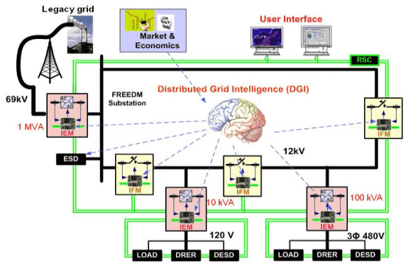
Figure 1 – FREEDM system topology and components
The overcurrent relays generations started with conventional electromechanical relays followed by static and digital relays. The last two generations prevent the overshooting errors and reduces time delay. Nowadays, microprocessor and microcontroller relays are introduced to eliminate their disadvantages. This leads to enhance power system protection; better reliability, reducing the impact on the electric power system equipment and facilitate power system automation. Microcontrollers deal with low voltage and current inputs and have good stability to the current variations. They contain RAM, ROM and other peripherals while microprocessors have only CPU [7]. In literature, Arduino Uno microcontroller was utilized for overvoltage and overcurrent protection of simple single phase-two terminal systems in [8] and for transformer protection in [7]. Differential protection of transformer technique was proposed using Arduino with GSM and voice circuit in [9]. The authors recommended to use Arduino in place of 8051 microprocessor as it is a low cost-effective device with very high speed and fine accuracy. A protective strategy was applied using Arduino controller to senses temperature and current and trip load at preset values [10]]. Transformer differential protection was employed using Arduino in [11-13]. The Arduino senses the condition of transformer each and every second. If it founds any error, then it sends commands to the circuit breakers to trip the main potential transformer. Finally, Arduino was utilized to monitor and protect motors against overvoltage, over-current, overload, excessive heating, crawling and under-voltage [14]. A Proposed software was introduced and fed by the real time data of the power system using Arduino in [15]. The software was used to recognize and indicate different types of fault conditions based on pre-set values, and then disconnected the load side.
In this paper an Arduino Uno microcontroller-based overcurrent relay with different characteristics (inverse, very inverse and extremely inverse) is designed for FREEDM systems. A Software simulator and a hardware circuit are designed and implemented. The designed practical printed circuit board is equipped with the required inputs and outputs as for the FREEDM system. A friendly program is created using Proteus software package and easily integrated to the hardware card. Different scenarios are applied to the simulator to satisfy the three types of overcurrent relay characteristics and the results are compared with the characteristics recorded by IEC 60255-151standard [16]. The normally inverse relay characteristics is tested and fulfilled using the practical circuit.
Problem statement
Overcurrent protection is very important to protect the branch connecting SST to the closed loop zones in the FREEDM system as shown in Fig. 2. The distribution bus may import the power from the medium voltage loop to the loads beside the local generation in case that the local generation power is lesser than the connected loads. Similarly, it may export power to the medium voltage loop in case that the local power is larger than the connected loads. The management of electric loads is activated by DGI (Digital Grid Intelligent) of the FREEDM unit. The SST is always a pi direction to perform the function of IEM. For these reasons, the overcurrent relay should be installed in the link between SST and the loop of FREEDM as shown in Fig. 2.
Figure 2 – Backup protection units
The backup protection unit of FREEDM system consists of three main protection schemes, overcurrent, over/under voltage, and differential protection schemes, as explained by Fig. 2. In this paper, a new design of an overcurrent relay using Arduino microcontroller is introduced. The proposed design has a very low cost, high speed and fine accuracy. The used Arduino microcontroller is quite efficient and easy for programming. The results, obtained from the proposed O.C relay are compared with the values obtained by the standard IEC characteristic curves in the three modes of operation (normal, very invers, extremely) and proofed very little errors.
Proposed technique
Overcurrent protection scheme is proposed as per the block diagram shown in Fig. 3 and flow chart in Fig. 4. Hardware Arduino microcontroller is utilized by downloading software program designed through Proteus package using C language. A software is created to satisfy different overcurrent relay characteristics (invers, very inverse and extremely inverse) which are required to protect FREEDM system. The followed standard characteristics is simulated in the program as per the following equations:
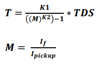
- T – Relay Operating Time,
- IТ – Fault current value,
- IY – Pickup (set start) current value,
- M – Current Multiplier,
- K1, K2 – Curve set-related parameters (inverse, very inverse, extremely inverse)
The value of current flows from supply to the load is sensed by hall effect current transformer. The current signal is converted to dc voltage using shunt resistance to suite the microcontroller requirements. The produced voltage signal which is proportional to this current value is fed to Arduino Uno microcontroller. The voltage signal is varied based on the actual current value in the main circuit. If value of current exceeds the pre-set value, an output signal is generated to trip the solid-state switch to disconnect the load and to display the fault current on the LCD.
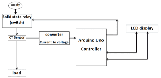
(а) block diagram of overcurrent relay
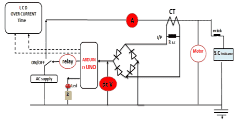
(b) Circuit diagram
Figure 3 – Proposed overcurrent relay using Arduino Uno controller
The process of the proposed technique is displayed as the flowchart in Fig. 4 and can be summarized as following:
- Select the values of K1, K2 according to the required mode of operation by adjusting resistance R1;
- Select the value of Time Dial Setting
TDS
using variable resistance R2; - Apply short circuit across the load. Short circuit value is varied by using variable resistance parallel with the load;
- Calculate M multiplier using (2) and identify operating time using (1);
- Derive characteristic curves for different modes using the corresponding values of M and T;
- Compare the characteristic curves for different modes with the standard characteristics of IEC for certain TDS.
Proposed circuit simulation and results
Three scenarios are simulated for inverse, very inverse and extremely inverse overcurrent relay characteristics at different TDS values.
А. Scenario-1: Proposed normally inverse overcurrent relay simulation
The procedure used to apply this scenario can be summarized in the following steps:
- Select normal inverse overcurrent relay using the mode push button shown in Fig. 4;
- Select TDS equal 0.05 by using TDS push button;
- Use different values of the variable short circuit resistance R4 to change the fault current IF;
- Obtain different values of both fault current and operating times according to the values of R4;
- Calculate the multiplier values for the chosen values;
- Draw the proposed normally inverse relay characteristics as in Fig. 5;
- Apply the same values of multipliers to the normally inverse relays specified in IEC 60255-151 and compare its characteristic against the proposed one as in Fig. 5;
- Calculate the percentage error for each value as tabulated in Table 1.
It can be noticed that the proposed extremely inverse overcurrent relay characteristic is nearly coincide with the same resulted from IEC standard as shown by Fig. 5. Very small errors are realized as illustrated by Table 1.

Figure 4 – Typical schematic diagram for Scenario 1 with TDS = 0.05
| If,(A) | 53 | 70 | 107 | 162 |
|---|---|---|---|---|
| Ipickup,(A) | 33 | 33 | 33 | 33 |
 |
1.61 | 2.21 | 3.24 | 4.91 |
| Operating time as per Arduino,(c) | 0.71 | 0.46 | 0.29 | 0.22 |
| Operating time as per IEC (Sec) | 0.72 | 0.47 | 0.3 | 0.23 |
| Error,(%) | 0.01 | 0.02 | 0.03 | 0.04 |
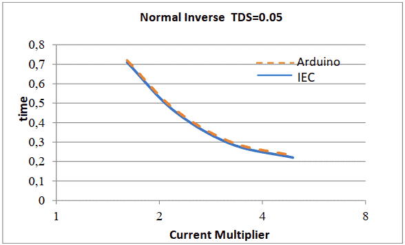
Figure 5 – Proposed normally inverse overcurrent relay characteristic at TDS=0.05 compared with IEC standard using simulator
B. Scenario-2: Proposed very inverse overcurrent relay simulation
The second mode very invers
can be obtained by changing the mode push button. The typical schematic diagram of this mode is shown in Fig. 6. The same steps used in scenario 1 are repeated and the obtained very inverse overcurrent relay characteristic values are tabulated in Table 2 and drawn in Fig. 7. The percentage error for each short circuit value is calculated and tabulated in Table 2. It can be noticed that the proposed very inverse overcurrent relay characteristic is nearly matched with the characteristic resulted from IEC standard and very small error is realized.
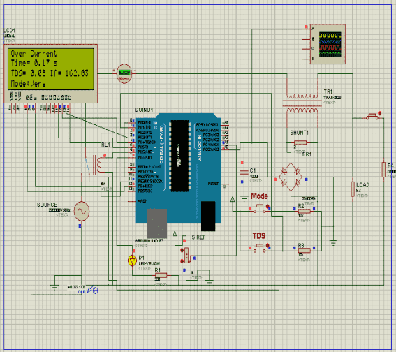
Figure 6 – Typical schematic diagram for Scenario 2 with TDS = 0.05
| If,(A) | 53 | 70 | 107 | 162 |
|---|---|---|---|---|
| Ipickup,(A) | 33 | 33 | 33 | 33 |
|
1.61 | 2.21 | 3.24 | 4.91 |
| Operating time as per Arduino | 1 | 0.6 | 0.29 | 0.17 |
| Operating time as per IEC (Sec) | 1 | 0.6 | 0.3 | 0.17 |
| Error,(%) | 0 | 0 | 0.03 | 0 |
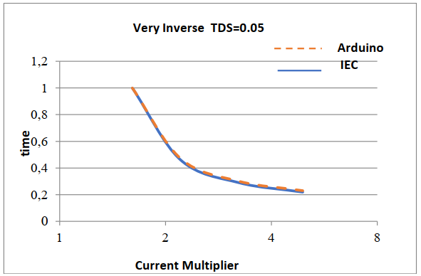
Figure 7 – Proposed normally inverse overcurrent relay characteristic at TDS=0.05 compared with IEC standard using simulator
С. Scenario-3: Simulation of extremely inverse overcurrent relay
This mode can be obtained by selecting the third mode extremely invers
. The typical schematic diagram for this mode is shown in Fig. 6. Similar to the above two scenarios, the extremely inverse overcurrent relay characteristic values are computed, tabulated and drawn. It can be observed from Fig. 7 that the proposed extremely inverse overcurrent relay characteristic is also coincide with the characteristics resulted from IEC standard with a very small errors explained by Table 3.
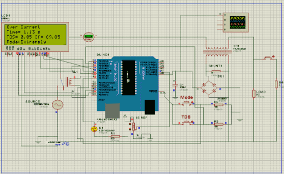
Figure 8 – Extremely characteristic of overcurrent relay at TDS equal 0.05
| If,(A) | 162 | 107 | 70 | 53 |
|---|---|---|---|---|
| Ipickup,(A) | 33 | 33 | 33 | 33 |
|
4.91 | 3.24 | 2.21 | 1.61 |
| Operating time as per Arduino | 0.17 | 0.42 | 1.13 | 2.42 |
| Operating time as per IEC (Sec) | 0.18 | 0.43 | 1.13 | 2.42 |
| Error,(%) | 0.05 | 0.02 | 0 | 0 |
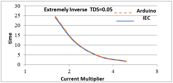
Figure 9 – Proposed extremely inverse overcurrent relay characteristic at TDS=0.05 compared with IEC standard using simulator
Conclusion
An Overcurrent relay was designed using Arduino Uno microcontroller. Software program has been created through Protos package using C language. To ensure the capability of the proposed overcurrent protection relay performance to a FREEDM system branch, software simulator and hard ware circuit has been developed. Software simulator has been formed to simulate normally inverse, very inverse and extremely inverse characteristics. A hardware circuit was fabricated using Arduino microcontroller board, uploaded with the created program and furnished with inputs and outputs to monitor and protect a motor load. Three overcurrent relay types have been applied to the software simulator and compared with the IEC 60255-151 standard behavior. The proposed relay characteristics nearly matched the standard ones. The error found between 1 to 4% for normally inverse, 3% for very inverse and 2 to 5 % for extremely inverse. The normally inverse characteristics has been tested and verified using a practical circuit and error found between 3.4 % to -10.5% compared to the IEC 60255-151 standard.
References
- A. Huang,
FREEDM System - A Vision for the Future Grid
, IEEE Power and Energy Society General Meeting, Providence, USA, 25-29 July 2010, pp.1-4 - N. Sharma,
Novel Directional Protection Scheme for the FREEDM Smart Grid System
, M. Sc. Thesis submitted to Arizona State University, August 2015 - Электронный ресурс: https://www.freedm.ncsu.edu/
- P. Mandava,
Design and Development of Protection Schemes for FREEDM Smart Grid Systems
, M. Sc. Thesis submitted to Arizona State University, December 2014 - O. Vodyakho, et.al.,
Solid-State Fault Isolation Devices: Application to Future Power Electronics-Based Distribution Systems
, IET Electric Power Application, Vol. 5, Issue 6, July 2011, pp. 521–528 - M. F. Kotb, M. El‐Saadawi, E. H. El‐Desouky,
Protection Coordination Optimization for Future Renewable Electric Energy Delivery and Management (FREEDM) System
, Journal of Electrical Engineering JEE, USA, 6(2018), pp. 161-176 - A. Agarwal,
Overcurrent Protection of Transformer by incorporating IDMT Function with the Help of Arduino Uno Microcontroller
, International Research Journal of Engineering and Technology (IRJET) Vol.: 03, Issue: 05, May-2016, pp. 1753-1755 - S. Bhattacharya, et al.
A Novel Approach to Overvoltage and Overcurrent Protection of Simple Single Phase Two Terminal Arduino Uno
, International Journal of Electrical Engineering, Volume 10, Number 1, 2017, pp. 97-110 - K. B. Trivedi, C. Vibhkar, R. Sardhara,
Differential Protection of Transformer Using Arduino with GSM and Voice Circuit
, International Journal of Novel Research and Development (IJNRD) Volume 2, Issue 4 April 2017, pp.95-100 - R. B. Pandhare, et. al.
Transformer Protection by Using Arduino with GSM Modem
, International Journal of Research in Advent Technology (IJRAT), Special Issue National ConferenceCONVERGENCE 2017
, 09th April 2017, pp. 119-123 - I. Sharma, T. Patel, D. Tailor,
Differential Protection of Transformer Using Arduino
, International Journal of Innovative and Emerging Research in Engineering Volume 3, Issue 7, 2016 - S. N. Syed, S. Radhika, M. N. S. Rani,
Differential Current Protection of Transformer Using Arduino with Voice Alert
, International Journal of Innovations in Engineering and Technology (IJIET), Volume 6 Issue 2 December 2015 pp. 206-212 - A. Naseem, N. Alam,
Protection of Distribution Transformer Using Arduino Platform
, Science International, Volume: 27, Issue: 1, 2015, pp. 403-406 - R. Waswani, A. Pawar, M. Deore, R. Patel,
Induction Motor Fault Detection, Protection and Speed Control Using Arduino
, International Conference on Innovations in Information, Embedded and Communication Systems (ICIIECS), Coimbatore, India, 17-18 March 2017 - A. Verma, S. L. Shimi,
Arduino Based Low Cost Power Protection System
International Journal of Advance Research, Ideas and Innovations in Technology (IJARIIT), Volume: 2, Issue: 4, 2012, pp. 1-7 - IEC 60255-151:
Measuring Relays and Protection Equipment–Part 151: Functional Requirements for Over/Under Current Protection
, International Electrotechnical Commission, 2009