
Abstract
Content
1. Analysis of existing designs of workpiece joggers.
According to the method of transmitting the pushing force, the following designs of joggers are distinguished: rack, screw, lever, chain, friction. Electromechanical drives are predominantly used to drive the joggers, but sometimes hydraulic or pneumatic drives are used.
The rack pusher (Fig. 1) is designed to move individual blooms and slabs from the roller table to the heating furnace and move the entire row of blanks through it.
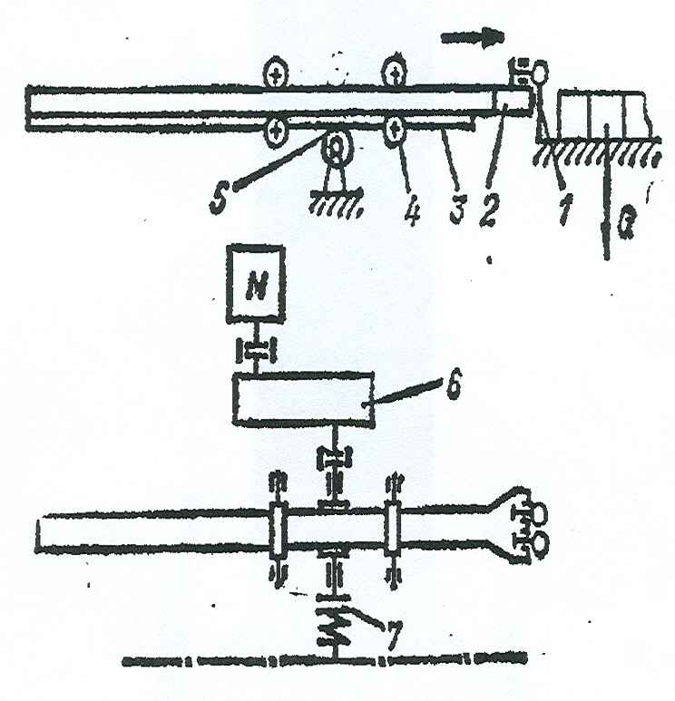
1 - pushing element;
2,3 - gear racks;
4 - guide rollers;
5 - gear wheel;
6 - reducer;
7 - connecting sleeve
The push rod is equipped with push fingers with spring shock absorbers. When the bar moves forward in the road wheels, the fingers rest against the end of the bar and push the bloom in front of them. When the rod moves back and there is the next bloom on the roller table, the fingers are deflected upward, and the head of the rod freely deflects to its original position, after which the closing spring presses the pushing fingers to the end of the rod. A toothed rack is fixed on the lower side of the rod, with the help of which the pushing force from the drive through the drive gear is transmitted to the rod. The speed of the workpiece, pushed by the rack and pinion, is 0.2 - 0.25 m / s.
The screw pusher (Fig. 2) feeds the blanks into the furnace, advances them along the course of the furnace and unloads them through the delivery window; used to overcome forces up to 700 kN with a ruler stroke up to 2.5 m.
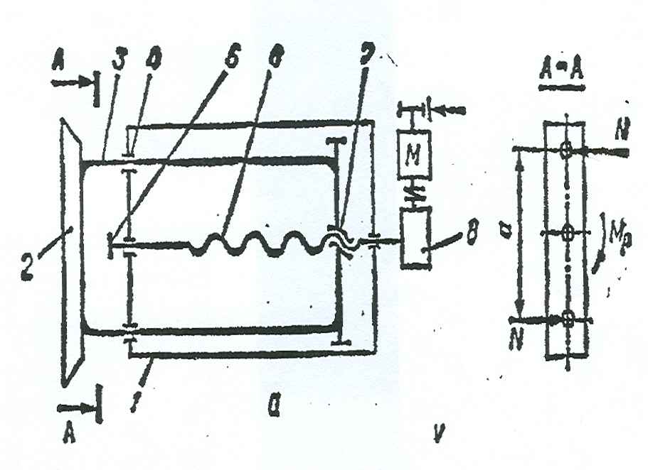
1 - bed;
2 - ruler;
3 - barbell;
4 - guide;
5 - bearing;
6 - screw;
7 - nut;
8 - reducer
The screw pusher consists of a fixed frame on which the front and rear posts are mounted. Attached to the front jay are rod guides, radial and thrust bearings for the front end of the screw. When the screw rotates, the nut and the associated traverse move. The traverse, in turn, is rigidly connected to the rear ends of the rods, which pass through the guide bushings of the A-pillar, and their front ends are attached to a common pushing head. This design ensures that the screw only works in compression. The screw rotates from a drive consisting of an electric motor, a gearbox, a coupling and a brake.
The disadvantages of screw projectiles are: rapid wear of the nut (service life no more than 2 years), low efficiency of the screw-nut pair itself. The advantage of screw joggers in comparison with rack and pinion are smaller dimensions and metal consumption.
The pusher rods are forged, welded and, for pushers designed for low effort, from rolled round blanks. Forged and welded rods are more difficult to manufacture, and the design of the guides is also more complicated. However, the use of rods of rectangular cross-section, for rack and pinion joggers, allows the toothed racks to be made in the form of separate parts, making them from more durable and wear-resistant steel (40X, 40XH), and when the teeth wear out, replace, keeping heavy and expensive rods. Round pusher rods are easier to manufacture, but in this case, the teeth have to be cut into them. In this case, when the teeth are worn, the rods must be replaced entirely.
In contrast to the designs of pushers, in which the rod with a long stroke and moves reciprocally as a result of the reversible movement of the electric motor, in the lever pusher (Fig. 3) the reciprocating movement of the pusher occurs with continuous rotation of the electric motor in one direction. Typically, lever pushers are designed for small and medium pushing forces with a movement speed of 2 ... 3 m / min and a pusher stroke within 200 ... 600 mm. The transformation of the rotational motion of the engine into the reciprocating motion of the pushing device in the lever pusher is as follows. The electric motor rotates the input shaft of the gearbox, on the output shaft of which there is a crank. The crank is connected by a connecting rod to a lever attached to the shaft.
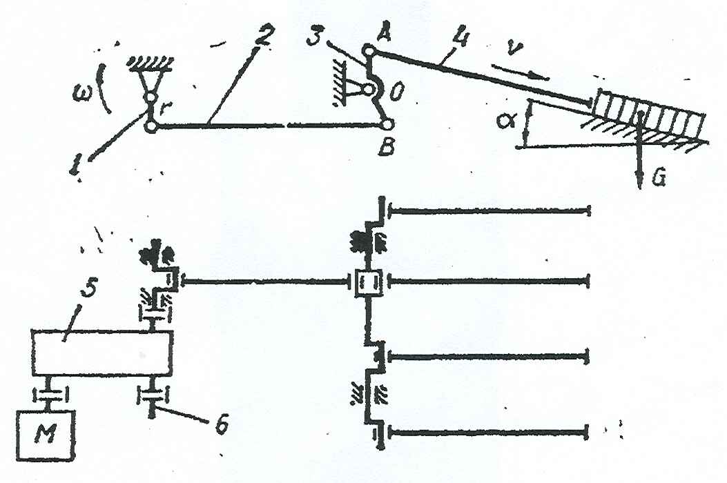
1 - shaft;
2 - connecting rod;
3 - lever;
4 - barbell;
5 - reducer;
6 - gearbox output shaft
Several short levers are mounted on the same shaft, to which push rods are pivotally attached at one end. The rods pass through the oven windows and slide at the other end on a guide plate inside the oven. When moving forward, the rods push the entire row of long workpieces through the furnace by the amount of travel. With the reverse movement of the rods between them and the end of the row of workpieces, the next workpiece is fed, after which the cycle is repeated. The bar is located at an angle that is approximately equal to the angle of inclination of the oven. The rod travel is 500 - 550 mm. Duration of working and idling 10 s.
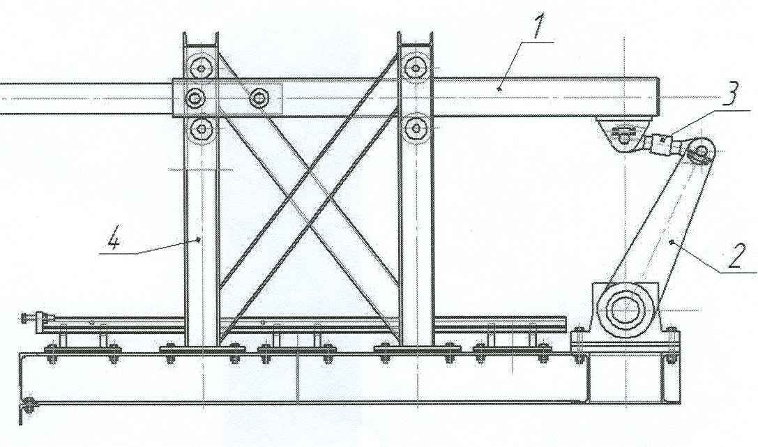
At this point in time, on mill 390 of the Makeevsky branch of PJSC "YMP", a lever pusher of workpieces is installed, the design of which is shown in Figure 4. By design, this pusher is similar to the design of the above described lever pusher. The differences are that the pusher of the 390 mill has a hydraulic drive instead of an electromechanical one, and the push rod 1 (Fig. 5) moves in the guide rollers 5 fixed on the frame 4. This pusher pushes one workpiece into the furnace, which enters the walking water-cooled beams of the furnace ...
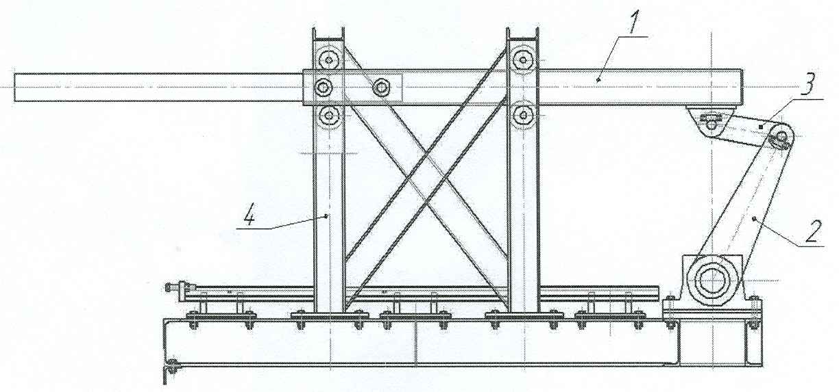
1 - pushing bar;
2 - lever;
3 - thrust;
4 - frame;
5 - guide rollers;
6 - shaft
During the operation of this pusher, the following drawback was revealed: when pushing the workpiece into the furnace, the pushing rods 1 do not simultaneously enter into operation. This is caused by inaccuracies in the manufacture of the elements of the pusher. As a result, the load from the force of pushing the workpiece is not redistributed evenly between the push rods and, accordingly, the shafts 6. This leads to twisting of the shafts and shearing of the rods 6.
To eliminate this drawback, it is proposed to replace rigid rods 3 with adjustable ones (Fig. 5). This solution will allow, by changing the length of the rods, to adjust the position of the push rods so that the latter simultaneously come into operation.
The adjustable rod consists of two lugs connected by a threaded rod. A right-hand thread is cut on one side of the rod, and a left-hand thread on the other. Accordingly, one lug has a right-hand thread, the other a left-hand thread. As the threaded rod rotates, it will either screw in or twist out of the lugs. Thus, the thrust length will change. To prevent spontaneous screwing in or out of the threaded rod during operation, two lock nuts are provided.
1 - push rod;
2 - lever;
3 - adjustable draft;
4 - frame;
5 - guide
rollers; 6 - shaft
Technical characteristics of pusher mill 390:
- cross-section of the colliding workpiece, mm 150 × 150
- length of the workpiece being pushed, m 12
- mass of the collided workpiece m s , kg 2120
Pusher hydraulic drive
- stroke h, mm 650
Collision cycle t c , s 6
- forward stroke t in , s 3
- stroke back t n , s 3
2. Types of shaft wear
During the operation of metallurgical equipment, there are various types of physical wear: plastic deformations and fractures; erosion-cavitation, corrosion, corrosion-mechanical and mechanical damage [2] .
Mechanical wear is the process of gradual destruction of the surface of parts during their relative movement. The classification of mechanical types of wear was developed by M.M. Khrushchev [3] , I.V. Kargelsky and E.M. Shvetsova [4] , B.I. Kostetsky [5] and others.
The contact surfaces of machine parts are characterized by microrelief and waviness, which, at the initial moment of operation of friction units, determine the area of actual contact, pressure and running-in time. During operation, under the action of working loads and deformations, a working relief is formed, consisting of depressions and protrusions. Their dimensions depend on the internal structure of the materials of the parts and the processes of plastic deformation. During the period of relative motion, elastoplastic deformations occur in the surface layers of the contacting parts, which, in turn, cause the appearance of secondary (physical, chemical, mechanical) processes.
Professor B.I. Kostetskiy distinguishes five main types of mechanical wear: set wear of the I and II kind, oxidative, smallpox and abrasive.
The first type of seizure wear is observed during sliding friction. Conditions for its occurrence: low speed of relative motion (up to 1 m / s for a friction unit consisting of two steel parts), high pressure exceeding the yield point at the sites of actual contacts, no lubricant or a protective oxide film, and low heating temperature of surface layers (up to 100 ° C).
The mechanism of destruction of friction surfaces is as follows. The interaction of working reliefs at pressures exceeding the yield point is accompanied by severe plastic deformations, as a result of which oxide films are destroyed and chemically pure metal surfaces are exposed. In addition, plastic deformations contribute to the maximum convergence of parts and the formation of textures in the surface layers from extremely deformed crystals located in the direction of relative velocity. If the distances are extremely small and commensurate with the dimensions of the atomic lattices, then between the oriented crystals of the two parts, metallic bonds (seizure) appear, shown in Fig. 6, and by dots and a line 1.
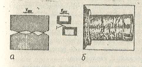
At extreme values of hardness and brittleness, metal bonds are broken. On the contact surface of a part made of a less durable metal, chaotically located breaks are formed, and on parts made of a strong metal, adhesions are formed. Adhered particles of high hardness contribute to the development of secondary processes of local plastic deformation and microcutting of friction surfaces. The external view of the surface of a part operating under conditions of 1st type seizure wear is shown in Fig. 6b, where chaotically located breakouts are clearly visible.
The wear rate of parts is 10 ... 15 μm / h. Friction forces are determined by the geometric characteristics of the working reliefs, the area of contact surfaces and the strength of metal bonds. The friction coefficient reaches 4 ... 6 units.
Oxidative wear develops under conditions of rolling friction and sliding friction at speeds of relative movement of parts of 1.5 ... 7 m / s (without lubrication). With boundary lubrication, the interval of relative velocities increases to 20 m / s.
The mechanism of destruction of surfaces is determined by complex interactions of materials of parts with oxygen of the environment: saturation of metals with oxygen due to chemical reactions (chemisorption), penetration of oxygen into the surface layers of parts (diffusion) and dissolution of oxygen in the surface layers (adsorption). These processes are most typical for friction units, parts of which are made of materials with high hardness and increased yield strength. Depending on the nature and intensity of diffusion, adsorption and chemisorption processes, the base metal in the surface layers of parts can transform into oxide films, solid solutions, and various chemical compounds of metal with oxygen.
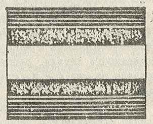
There are three forms of oxidative wear. The first is characterized by the continuous formation and destruction of ultramicroscopic films of adsorption oxides. Noticeable plastic deformations and diffusion phenomena are noted. The second form of oxidative wear manifests itself when disordered solid solutions and eutectics of metal-oxygen chemical compounds appear in the surface layers of parts. The third form is continuous films of chemical compounds of metal with oxygen. The wear of surfaces is the periodic appearance and chipping of hard and brittle chemical compounds. The appearance of a part operating under oxidative wear conditions is shown in Fig. 7. In the center, a matte strip is visible, consisting of oxides, solid solutions and chemical compounds of metal with oxygen.
The wear rate is minimal in comparison with other types of mechanical wear and is 0.1 ... 0.5 μm / h. The coefficient of friction depends on the shape and ranges from 0.3 to 0.7.
Type 2 set wear. The conditions for its formation: sliding friction, high pressures and speed of relative movement (υ rel > 4 m / s), the combination of which leads to large energy losses for friction, a high gradient and an intensive increase in temperature in the surface layers (up to 1600 ° C). The mechanism of surface destruction depends on the intensity of external mechanical influences and the properties of the materials of the parts.
There are three stages of 2nd kind set wear. The first stage corresponds to the temperature range that slightly reduces the mechanical properties of materials (for steels up to 600 ° C). As the temperature rises, the mechanical properties of the steel decrease, and a point may come when the pressures rise above the actual yield point. In this case, the interaction of the working reliefs, accompanied by severe plastic deformations, leads to the destruction of oxide films and the formation of metal bonds. The further course of the destruction mechanism is the same as in the case of seizure wear of the 1st kind, but the appearance of the surfaces has a significant difference: the breakouts of particles onto parts made of less durable material are not randomly located, but alternate at approximately equal intervals (Fig. 8, a) ...
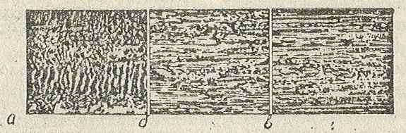
The second stage of wear develops in the temperature range 600 ... 1400 ° C. This temperature significantly reduces the mechanical properties of the steels, and the metal softens. The destruction of parts is characterized by contact seizure and plastic rupture of metal bonds. Adhesion and smearing of metal are visible on the contact surface of a more durable part (Fig. 8, b), and tears on the surface of a less durable part.
The melting temperature corresponds to the third stage of wear. The molten metal layers are carried away with lubrication, and melted grooves appear on the friction surfaces (Fig. 8, c).
The wear rate of parts is 1 ... 5 μm / h. The coefficient of friction ranges from 0.1 to 0.5.
Pointed wear occurs during rolling friction, variable or alternating loads and high pressures reaching the endurance limit.
The mechanism of destruction of surfaces according to the theory of A.K. Dinnik, N.M. Belyaeva and others is as follows. The interaction of two elastic bodies with spatially curved surfaces in the volume of the metal located under the point of contact A (Fig. 9) causes normal σ and tangential τ stresses. The maximum normal stresses correspond to the x = 0 coordinate, and the maximum tangents correspond to the y = 0.7a coordinate, i.e. appear not on friction surfaces, but inside parts. The areas of total maximum stresses are located at some angle β (β <45º) to the contact plane. Multiple loads cause material fatigue, and, as a consequence, cracks nucleate on the planes of maximum stresses inside the part. Their development leads to rupture of the contact surface, which fundamentally changes the nature of the interaction of parts. The movement of the ball through the discontinuity of the surface is accompanied by dynamic phenomena. If the ball moves to the left, then shock loads cause work hardening and shearing of the first section along the arrow c. When the ball moves to the right, chipping of the II section is observed. Pox-like depressions appear on the contact surfaces in places where chips are formed. The intensity of the formation of microcracks depends on the stresses arising in the parts during the machining period and various concentrators. Pox-like depressions appear on the contact surfaces in places where chips are formed. The intensity of the formation of microcracks depends on the stresses arising in the parts during the machining period and various concentrators. Pox-like depressions appear on the contact surfaces in places where chips are formed. The intensity of the formation of microcracks depends on the stresses arising in the parts during the machining period and various concentrators.

Abrasive wear develops during sliding friction. The conditions for its occurrence: the presence of abrasive particles on the friction surfaces, deforming the microvolumes of the surface layers and causing microcutting processes. The intensity of wear depends on the size, shape, properties of abrasives and materials of parts, on the relative speeds and pressures. The wear rate of parts ranges from 0.5 to 5 μm / h.
Fracture - destruction of a part caused by low quality material, manufacturing defects, violations of operating rules, accidental mechanical damage and other factors. By the nature of the loading of parts, static and fatigue fractures are distinguished. Static fractures are caused by excessive short-term loads. These fractures, depending on the loading rate and the initial structure of the material, can be tough and brittle.
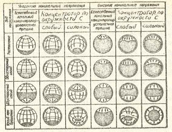
Fatigue fractures arising under the action of cyclic loads are different in appearance, but they all arise from small cracks, which, while increasing, completely destroy the shaft. The classification of fatigue fractures (Fig. 10) was proposed by prof. V.M. Grebennik [3] . The arrows in the figure show the direction of crack front propagation; moderate rated stresses correspond to the lower half of the fatigue curve, and high ratings correspond to the upper half. This classification makes it possible to assess the type and significance of the working loads, the design features of parts that contribute to the development of fatigue fractures. It clearly illustrates the conditions for the initiation and development of cracks and can be used to develop measures aimed at reducing equipment breakdowns.
Corrosion damage is the process of destruction of parts due to chemical or electrochemical interaction with the environment.
Chemical damage occurs in electrically neutral media during reactions between shaft material and active components of the external environment (for example, oxygen, sulfur dioxide). As a result, unstable oxide films are formed, the destruction of which under the action of working forces changes the geometric dimensions of the parts. Corrosion damage caused by electrochemical action occurs when points or areas with different electrical potentials appear on the surface of the shaft. For example, grain boundary and core, stressed and unstressed metal regions, pure metal and oxides. The anode sections have a higher electronic potential and therefore are subject to destruction.
Depending on the properties of the external environment, corrosion in electrolytes is distinguished, atmospheric and gas. Atmospheric corrosion develops at normal pressure and temperature not exceeding 80 ° C. The environment of metallurgical workshops contains moisture, various salts, alkalis and acids, the aqueous solutions of which are electrolyte. It is deposited on the parts and promotes the formation of microvoltaic cells. The destruction of the surfaces of the shafts at the initial moment has a point character, and later it is continuous. The external environment for gas corrosion is gases, hot air and steam. Many parts of metallurgical machines undergo such wear due to the interaction of the contacting surfaces with atmospheric oxygen.
Erosion-cavitation damage is formed during the period of contact of parts with high-speed liquid and gas flows. The mechanism of surface destruction is the continuous formation of oxide films. The wear rate of parts increases if there are solid particles in the flow.
Corrosion-mechanical damage (corrosion fatigue and cracking, fretting corrosion) appears on the surface of parts under the influence of corrosion and mechanical factors. Corrosion fatigue is a process of intensive destruction of parts with the simultaneous action of corrosion and cyclic stresses. Stress corrosion cracking is caused by corrosion and static stress. Fretting corrosion occurs when press fit or shrink fit parts make small relative movements. The mechanism of destruction of parts consists in the periodic formation of protective films of oxides at the boundary of the contacting surfaces [2] .
Conclusions. After analyzing the signs and conditions for the occurrence of types of shaft wear, as well as the fact that the main shaft operates in torsion and bending under variable loads, it can be concluded that the fatigue nature of the main shaft fracture as a result of the occurrence and development of a fatigue crack. The journal journals of the main shaft are primarily subject to abrasive wear due to poor quality seals and improper lubrication.
Bibliography
-
Радчик И., Рябков В., Сушко А. Комплексный подход к вопросам повышения надёжности работы основного и вспомогательного оборудования современного металлургического производства. Журнал
Национальная металлургия
, №1, 2006, с.24-29. -
Седуш В.Я. Надежность, ремонт и монтаж металлургических машин. – К.: НМК ВО, 1992.– 368 с.
-
Гребенник В.М. Усталостная прочность и долговечность металлургического оборудования. – М.: Машиностроение, 1969. – 256 с.
-
Хрущов М.М. Классификация условий и видов изнашивания деталей машин// Трение и износ в машинах. Сб. VIII. – М.: Изд-во АН СССР, 1953. – С. 5 – 17.
-
Швецова И.Е., Крагельский И.В. Классификация видов разрушения поверхностей деталей машин в условиях сухого и граничного трения // Трение и износ в машинах. Сб. VIII. – М.: Изд-во АН СССР, 1953. – С. 18 – 38.
-
Костецкий Б.И. Сопротивление изнашиванию деталей машин. – К.: Машгиз, 1959. – 478 с.
-
Іванченко Ф.К., Гребеник В.М., Ширяєв В.І. Розрахунок машин і механізмів прокатних цехів. – Київ: Вища школа, 1995. – 455 с.