
Abstract
- Introduction
- 1 Description of the electromechanical wheelchair
- 2 Description of typical protections in the electric drive and disadvantages of the existing solution
- 2.1 Protection modeling
- 2.2 Protection against simultaneous activation of keys in the rack
- 3 Implementation of protections
- Conclusions
- List of sources
Introduction
Among products intended for people with disabilities, a special class is allocated to technical means that compensate for violations of the human musculoskeletal system, for example, canes, crutches, lower limb prostheses, wheelchairs and wheelchairs. A wheelchair, unlike a wheelchair, is designed to be controlled by a disabled person independently, and not by an accompanying person. Wheelchairs can have a mechanical drive, in which the wheels are driven by hand force, as well as an electric drive, which includes: a battery, a power converter, a microcontroller, an input device and a gearbox. Such wheelchairs are designed to move not only indoors, but also outdoors, so it is important that the microcontroller has a convenient and reliable protection system that, in the event of a malfunction, can solve the problem. The Invacare Storm Power Stroller features a stylish design and easy handling, built to the highest standards in terms of configurability, adjustment and functionality. Thanks to its modular design, Invacare Storm can be easily upgraded according to user requirements and does not require complex maintenance. The Storm chair has been designed with "Ease of Use" in mind, and the modern design of the Storm emphasizes its robust construction and good driving performance. The purpose of the thesis is to develop a system of protective functions for the Storm XS electric wheelchair from Invacare. This is one of the first models in the series. This wheelchair is a combined type (suitable for both indoor and outdoor use) with individual rear wheel drive. The motors used are 350W GP8040SB-SRG1 DC commutator geared motors with a rated voltage of 24V, a rated current of 14A, and a rated speed of 4000rpm. The gear ratio of the gearbox is 25.1, and the diameter of the driving wheels is 36 cm. The set includes two batteries with a nominal voltage of 12 V each and a capacity of 40 Ah. This wheelchair is convenient because the armrests and footrest are adjustable in height, there is also depreciation of the rear wheels. Electromagnetic brakes with a nominal force of 2.2 N?m are attached to the motors. The weight of the wheelchair is approximately 70 kg without batteries and 103 kg with batteries. Rated load capacity - 110 kg. The problem of helping people with disabilities remains one of the most complex, requiring society not only to understand it, but also to participate in this process of many specialized institutions and structures. Rehabilitation of the disabled is not only treatment and improvement of health, but also the process of a person achieving maximum independence in society. Some of the devices most conducive to this are prosthetic limbs and electromechanical wheelchairs.
1 Description of the electromechanical wheelchair
Nowadays, unfortunately, there are many people who are unable to move independently, so a powered wheelchair is an excellent means of transportation - it allows you to lead a full-fledged lifestyle without using the forces of strangers at all. Electrically powered wheelchair – Any landing surface with wheels attached to it, powered by an electrical power source, usually electric motors and batteries. The first powered wheelchairs appeared in the early 1900s, but the demand for them did not exist until the end of World War II. The first commercially produced electric wheelchairs were simply heavy manual folding wheelchairs powered by lead-acid batteries, electric motors, drive belts and pulleys. These systems, known as conventional electric wheelchairs, were very simplistic. They needed to use a joystick to control the movement of the wheelchair, and programmability didn't exist. The seating system typically consisted of a hanging seat and back padding, which greatly limited posture for the individual. The advent of the power base, which was under the seat and contained the motor and batteries, enabled significant mechanical advances in electric wheelchairs. The power base divided the electric wheelchair into two parts: the base providing mobility and the seating system providing support for the body. At the same time as the transition from the conventional power wheelchair to the more advanced power wheelchair was taking place, significant advances were made in electronic systems. Some of these mechanical and electrical improvements included the ability to add tilt systems, power adjustment, and programmable performance settings (such as forward speed, turn speed, and acceleration). Joysticks are the most basic and common devices used to control electric wheelchairs. Advances in control systems have allowed people to control a wheelchair using any voluntary movement. For example, some electric wheelchairs can be controlled by head movement, breath activation, tongue movement, or lower limb control. Two types of drive mechanisms are used on electric wheelchairs: indirect drive and direct drive. Indirect drive systems (pulleys and drive belts) are used on conventional electric wheelchairs, while direct drive systems (usually via a gearbox) are used on power-assisted wheelchairs. The vast majority of modern electric wheelchairs use a power base with a direct drive system. Typically, two 12V batteries connected in series (24V total) are needed to power an electric wheelchair. Electric wheelchairs may use wet batteries, gel batteries, or batteries with absorbent glass. Wheelchair batteries are usually rechargeable. Electric wheelchairs can also be classified into drive wheel arrangements. There are three types of electric wheelchairs: front, middle or center, and rear. Traditionally, rear-wheel-drive electric wheelchairs have been favored due to their similarity to manual wheelchairs in design and maneuverability. However, center-drive wheelchairs have gained popularity as they provide increased maneuverability. Power-operated wheelchairs (PAPAW) incorporate the features of both manual and electric wheelchairs. The PAPAW usually consists of an ultra-light manual buggy with an external power source (batteries and motors). It complements rather than replaces the ability of a person to manually move a wheelchair. The pusher contains sensors that determine the direction and magnitude of the force applied to it by a person. The motors are then activated and assist in the movement of the stroller.
2 Description of typical protections in the electric drive and disadvantages of the existing solution
Emergency modes in the electrical circuits of the engine can be:
- short circuits;
- short-term and long-term current overloads of the motor;
- interruptions in power supply, unacceptable decrease in mains voltage;
- overvoltage in the power circuit;
- software-related errors.
Protection against short-circuit currents and overcurrent protection is carried out using instantaneous overcurrent relays, automatic switches (automatic devices), as well as fuses. Fuses provide a low set point accuracy, which also changes over time due to corrosion. In addition, even correctly selected fuses do not protect the AD from two-phase operation. In cases where it is necessary to ensure greater accuracy of trip settings, instantaneous overcurrent relays acting on contactors or high-voltage circuit breakers are used. They turn off the motors in the event of short circuits, short-term current overloads.
2.1 Protection modeling
The main tasks of the electric drive control system are: the implementation of the start, the synthesis of the current control loop, the creation of the necessary operating mode, and the provision of reverse. In addition, the control system may contain various protections and additional functions. Most often, they try to perform basic tasks with built-in protections.
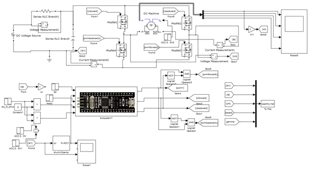
Figure 1 - Model of the control system for one engine
This model can be divided into two parts: the first part is a power one, it includes a DC motor, Mosfet power switches, a power supply, the second part is a motor control system that sets up a current regulator and a PWM generator, receives reference signals from a smartphone, calibrates and current measurement. The input of the microcontroller receives signals from a smartphone via Bluetooth. To simulate signals, we will compose a subsystem shown in Figure 2. A battery with a voltage of 24 V was chosen as a power source. The upper keys are responsible for the direction of rotation, the lower keys set the speed. The Smartphone subsystem simulates the task signals from the smartphone, which come to the microcontroller from the Bluetooth module. The shunt + Opamp AD823 subsystem simulates an op amp shunt. The STM32F401CC subsystem imitates a microcontroller in which the signal from the current sensor is calibrated, the PI controller is tuned, etc. Blocks IR2104 are drivers for power switches.
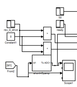
Figure 2 - Subsystem that simulates signals from a smartphone
The shunt + Opamp subsystem simulates a shunt with an operational amplifier, designed to convert and scale the current flowing in the motor into the voltage required to operate the microcontroller. The subsystem is shown in Figure 3.
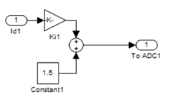
Figure 3 - Shunt + Opamp Subsystem
The STM32F401CC subsystem receives signals from a smartphone and, through logical operations, processes the input signals and sends commands to the power section to Mosfet transistors to control the motor. This subsystem converts and scales the current flowing in the motor into the voltage required to operate the microcontroller. With a current flow of 10 A, the output will be 1 V. A 1.5 V bias has been added to the system to observe the current in generator mode. The output of the subsystem goes to the ADC of the microcontroller in the STM32F401CC subsystem.
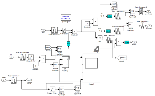
Figure 4 - Subsystem STM32F401CC
When a signal comes from the sensor, the microcontroller needs to know what voltage value corresponds to zero current, because the output of the current sensor has various noises and interference. In order to determine the zero current value, it is necessary to add a filter, with a constant time T=0.01 s, and record the value of the resulting signal after 8T, which corresponds to 80 ms. When 1 is applied to the input of the integrator, time goes on the output, when it reaches 80 ms, the signal from the filter is recorded through the input in current1. This filter converts data from single integer format to uint16 floating point format. This is necessary for the filter to work, since the filter cannot work with integers. The output of this filter is fed to the input of the integrator U0 and after 80 ms the filtered zero current value will be written to the microcontroller at the output Out1. A signal with a minus sign comes from the output of the calibrator and subtracts the calibrated value from the obtained value. Next, an inverse conversion is made from 4096 bits to 3.3 V to obtain a voltage, and to obtain a current value, it is necessary to multiply these readings by 10 so that 1 V corresponds to 10 A, with a further factory of this value in the Product block. The shunt is located so that when moving forward or backward, the current moves in one direction, so an additional signal is taken from the Sign block, where the sign changes when moving backward. The signal ? at the input of the Sign block is positive when moving forward and negative when moving backward. The signal from the Product block, which is fed to the current regulator, forms a negative current feedback. The reset and ready inputs go to the Rate Transition blocks, switching the step from a very small step of 1 µs, which is close to a continuous system, to our microcontroller's step of 100 µs. This discrete step is selected based on the frequency of the PWM equal to 10 kHz. Further, the signal ? is fed to separate control areas: the upper part with outputs Lbackward and Lforward is responsible for the direction of movement forward and backward, and the lower part forms a PWM generator. In the upper part, the signal ? is compared: if ? is greater than zero, then we move forward Lforward, and if ? is less than zero, backward Lbackward. The PWM generator itself is generated in the block. Triangle, and the signal has the shape of a saw with a frequency of 10 kHz. This output is compared with the current value of ? and the PWM1 signal is obtained. The Abs block must be used because the input signal can be either positive or negative. In addition, the permission signal from the ready input is also received at the input of the Product block. The value of the PWM generator from the Triangle block is compared with one (the lower peak of the sawtooth signal), while an analogue of an interrupt occurs in the form of a pulse, with which the measured current is digitized exactly at the middle of the pulse duration. Further, this pulse enters the input integrator after the 12-bit ADC, thereby writing the value of the integrator from the input U0 when the leading edge of this pulse is reached. The powergui block is required for the operation of the entire system with a discrete step of 1 µs.
2.2 Protection against simultaneous activation of keys in the rack
The H-bridge consists of power P and N channel MOSFETs, power diodes with a Schottky barrier, and key control circuits. Transistors Q5 (Q12) and Q6 (Q11) are P-channel IG MOSFETs with built-in freewheeling diode. These transistors operate in static mode, and are responsible for the direction of rotation of the motor. In simple terms, they do not need a high switching frequency. These transistors are controlled by a voltage divider and shunt transistor Q1 (Q4) and Q2 (Q3). If a logical “1” is applied to the base of the bipolar transistor from the microcontroller, the transistor opens, thereby connecting the divider assembled on resistors R2, R3, R5, R7 (R27, R26, R25, R24) and creating a voltage equal to half the supply voltage - 12V. Bipolar transistors Q1 (Q4) and Q2 (Q3) can be used with any supply voltage of 50 V and a maximum collector current of not more than 100 mA. Capacitors C2 (C19) and C3 (C18) are noise suppressors, they prevent false opening of the power transistor during inductive surges in the power circuit. It is recommended to use an additional electrolytic capacitor C1 (C26) with a capacity of 500 uF for every 10 A of current flowing in the load. Transistors Q7 (Q10) and Q8 (Q9) are N-channel IG MOSFETs with built-in freewheeling diode. These transistors operate at a frequency of 10 kHz, so they are subject to more stringent requirements. For transistors to operate in the high current region, sufficient gate voltage is required to provide the desired current-voltage characteristic. The control voltage of 12 V will be supplied to the gate from a special driver. This voltage is sufficient for the operation of power switches in the zone of high currents. In this circuit, there are diodes D1 (D4), D6 (D7) and D8 (D5) with a Schottky barrier. Diodes D6 (D7) and D8 (D5) are protective for the upper and lower transistors when the bridge is operating on an active-inductive load. In typical circuits, the presence of capacitance in MOSFETs can lead to through currents, especially at high switching speeds dV/dt of the power transistors. At a high switching speed, this current will flow through the capacitance located between the drain and the gate of the transistor. Also, the presence of this capacitance increases the risk of gate breakdown during switching. This is due to the fact that this capacitance can be charged by the supply voltage, and as you know, the gate voltage should not exceed 20 V (for N-channel - 17 V). When the high-side transistor turns on, the drain-to-source voltage of the opposite transistor decreases at a rate of dV/dt. The edge of this voltage creates a current flowing through the capacitance, the gate resistor and the output stage of the driver, which creates a voltage drop across the active resistance in the gate circuit. If the resulting potential exceeds the gate threshold voltage VTH, a false opening of the transistor will occur, followed by a short circuit or breakdown of the gate (Figure 2.9). This effect is caused by the so-called Miller capacitance. In addition to the presence of parasitic capacitance, MOSFET transistors should not operate without protection in the presence of reverse current. Diodes built into the transistor solve this problem, but you should not rely on them due to insufficient opening speed and signal rise. If current passes through the MOSFET in the opposite direction, a false opening will also occur, and at large values of this current, the channel will breakdown. However, by using these diodes, we thereby blocked the reverse current flow path, so an additional diode D1 (D4) was installed. All diodes are selected with a margin of voltage and current.
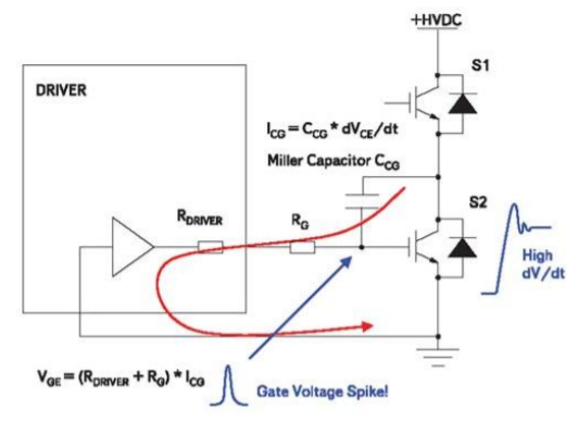
Figure 5 - False turning on of the transistor due to Miller capacitance
It is not safe to connect any MOSFETs directly to the microcontroller due to internal channel capacitances. Even if you limit the maximum current flowing on the gate, this does not guarantee that the microcontroller will not fail with such a connection. Microcontrollers also output from 3.3 to 5 V, which is not enough for transistors to operate in the high current region. Low voltage can only be driven by a small load. Otherwise, the transistor will overheat due to operation in an unstable mode. With such a connection, there is a high probability of failure of the microcontroller, since it will work on an active-capacitive load, this is due to the peculiarity of the transistor gate charge.
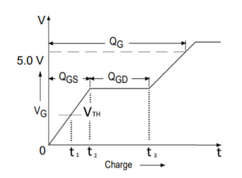
Figure 6 - MOSFET Gate Charging Process
The time from zero to t1 is called Turn-on delay, at this moment the transistor is closed. The voltage VTH is called Gate Threshold Voltage - the minimum opening voltage of the transistor. In the interval from t1 to t2, the drain current begins to increase linearly to a maximum. During this time, the transistor has time to fully open, while the drain voltage stops increasing. A further increase in the charge on the QGD gate, in the time interval t2 - t3, reduces the internal resistance of the drain-source junction to the passport value RDS(on). This value is available in the documentation of transistors. This phenomenon is also called the Miller effect.
The wheelchair motor has an IR2104 driver with input and output characteristics of this kind:
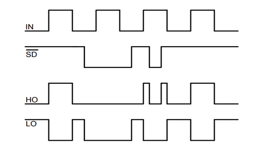
Figure 7 - Input / output characteristics of the IR2104 driver
Looking at the input / output characteristics of the driver and the characteristics on the circuit diagram, we can say that when a pulse comes from DIRL1 to IN, then at the Low Output we allow the signal to be received and the voltage passes through it. The PWM1 PWM compares the values using the Shutdown input characteristic on two motors and, depending on the similarity of the signals, either enables or disables and does not allow the voltage to pass in two sections, thereby working as a short circuit protection on the motors.
3 Implementation of protections
Electromechanical wheelchair Invacare Storm SX is one of the first models of this series. This wheelchair is a combined type (suitable for both indoor and outdoor use) with individual rear wheel drive. The motors used are 350W GP8040SB-SRG1 DC commutator geared motors with rated voltage 24V, rated current 18A and no-load speed 4000rpm. The gear ratio of the gearbox is 25.1, and the diameter of the driving wheels is 36 cm. The set includes two batteries with a nominal voltage of 12 V and a capacity of 40 Ah each. Electromagnetic brakes with a nominal force of 2.2 N•m are attached to the motors. Understanding the differences between AC and DC provides a clear understanding of the challenges faced by DC circuit breakers. Alternating current of industrial frequency (50 Hz) changes its direction in the electrical circuit 50 times per second and “passes” through the zero value the same number of times. This "passage" of the current value through zero contributes to the rapid extinction of the electric arc. In DC circuits, the value of the voltage is constant as well as the direction of the current is constant in time. This fact significantly complicates the extinguishing of the DC arc, and therefore requires special design solutions. One such solution is the use of a permanent magnet. The movement of the arc in a magnetic field is one of the methods of extinguishing in devices up to 1 kV and is used in modular automatic switches. An electric arc, which is essentially a conductor, is affected by a magnetic field, and it is drawn into the arc chute, where it finally fades.
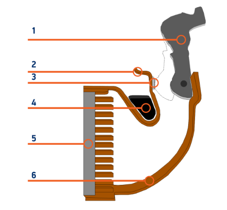
Figure 8 - The device of the modular circuit breaker 1 - movable contact, 2 - fixed contact, 3 - silver-containing contact soldering, 4 - magnet, 5 - arc chute, 6 - bracket.
Another and, perhaps, the key difference between AC and DC circuit breakers is the presence of polarity in the latter. When connecting circuit breakers to the DC network, the correct polarity must be observed. When connecting a single-pole DC switch, the supply voltage is supplied to terminal "1", and when connecting a two-pole DC switch, to terminals "1" and "4". Since there are two 18 A motors, you will need a 36 A DC circuit breaker, but you need to take a circuit breaker with a small margin, so we look at approximately 40 A. A suitable option on the Internet: OptiDin BM63-1C40-DC-UHLZ automatic modular circuit breaker

Figure 9 - Automatic modular circuit breaker OptiDin BM63-1C40-DC-UHLZ
Fuses are widely used to protect electrical wiring and expensive radio equipment from short circuits, surges in the supply network and ensure the safe operation of electrical appliances. They are produced in different designs, standard sizes and for any protection currents. The considered fuse repair technology, subject to all conditions, will ensure its protective function. But not everyone has experience with a soldering iron and measuring wire diameter. And in any case, an industrial-made fuse will work more reliably.
A tubular fuse is a glass or ceramic tube, closed at the ends with metal caps, which are interconnected by a wire calibrated in diameter, passing inside the tube. For the task, a fuse was selected in the form: ABB E9F 14 GG 50A 14X51MM 2CSM256333R1801

Figure 10 - ABB fuse and its cost
The decision was made to protect the transistors at the MOSFET outputs from burning out. For this, it was decided to use a transistor in the key mode.
Conclusions
In this project, hardware and software protection for the Invacare Storm XS wheelchair was developed and analyzed. To accomplish this task, a protection system based on the STM32F401CC microcontroller was developed and implemented. A circuit diagram of the MOSFET driver has been developed. To ensure the protection of the wheelchair, transistor fuses are used in the key mode, the wheelchair model is configured in MATLAB. Oscillograms of currents were obtained and analyzed under various critical conditions and in the normal state. The skills gained during the work make it possible to realize their skills in further work with protections and microcontrollers, in particular, with STM boards, and create more complex projects.
At the time of writing this essay, the master's work has not yet been completed. Estimated date of completion of the master's work: June 2023. The full text of the work and materials on the topic can be obtained from the author or his supervisor after the specified date.
List of sources
References
- Gilbert Ndayisenga, Omar Gatera, Charles Kabiri, Janvier Niyitegeka, Delphine Bampire, Sophonie Harerimana, "IoT Based Household Water Consumption Management System", 2022 IEEE PES/IAS PowerAfrica, pp.1-4, 2022.
- Manoj Saini, Shagufta Khan, Vipul Dutt Mishra, Manav Mehra, Deeksha Singh, Gopal Sengar, "IoT Based Hybrid EV Charging System with Data Processing", 2022 International Conference on Intelligent Controller and Computing for Smart Power (ICICCSP), pp.1-5, 2022.
- A. V. Zinkevich, "ESP8266 Microcontroller Application in Wireless Synchronization Tasks," 2021 International Conference on Industrial Engineering, Applications and Manufacturing (ICIEAM), 2021, pp. 670-674.
- P. Macheso, T. D. Manda, S. Chisale, N. Dzupire, J. Mlatho and D. Mukanyiligira, "Design of ESP8266 Smart Home Using MQTT and Node-RED," 2021 International Conference on Artificial Intelligence and Smart Systems (ICAIS), 2021, pp. 502-505.
- Jevgenijs Telicko, Andris Jakovics, "Power efficient wireless monitoring system based on ESP8266", 2022 IEEE 63th International Scientific Conference on Power and Electrical Engineering of Riga Technical University (RTUCON), pp.1-6, 2022.
- Falia Innocentia Ananda Sunarko, Epyk Sunarno, Diah Septi Yanarati, Eny Kusumawati, "Smart DC Home for Energy Saving with Android-Based Real-Time Energy Monitoring", 2022 International Electronics Symposium (IES), pp.156-161, 2022.
- S. S. Pakalapati, G. G. Chary, A. K. Yadaw, S. Kumar, H. K. Phulawariya and R. Kumar, "A prosthetic hand control interface using ESP8266 Wi-Fi module and Android application," 2017 International Conference on Innovations in Information, Embedded and Communication Systems (ICIIECS), 2017, pp. 1-3
- Ivan Vaccari, Maurizio Aiello, Federico Pastorino, Enrico Cambiaso, "Protecting the ESP8266 Module from Replay Attacks", 2020 International Conference on Communications, Computing, Cybersecurity, and Informatics (CCCI), pp.1-6, 2020.
- Ziyu Wan, Yunkai Song, Zhuli Cao, "Environment Dynamic Monitoring and Remote Control of Greenhouse with ESP8266 NodeMCU", 2019 IEEE 3rd Information Technology, Networking, Electronic and Automation Control Conference (ITNEC), pp.377-382, 2019.
- Thongchai Pornchaiyasutthi, Tanapat Anusas-amornkul, "A Model for Victim-Rescuer Communications under Collapsed Structures using Node MCU ESP8266", Proceedings of the 2019 2nd International Conference on Electronics, Communications and Control Engineering - ICECC 2019, pp.34, 2019.
- P. S. B. Macheso, T. D. Manda, A. G. Meela, J. S. Mlatho, G. T. Taulo and B. M'mame, "Environmental Parameter Monitoring System Based on NodeMCU ESP8266, MQTT and Node-RED," 2022 International Conference on Computer Communication and Informatics (ICCCI), 2022, pp. 1-4.
- P. Srivastava, M. Bajaj and A. S. Rana, "IOT based controlling of hybrid energy system using ESP8266," 2018 IEEMA Engineer Infinite Conference (eTechNxT), 2018, pp. 1-5
- Farah Khaliq Baloch, Ghulam E Mustafa Abro, Waheed Ali Laghari, Zubair Adil Soomro, Asif.A. Rahimoon, Rahul Kumar, "Controlling and Monitoring of Hybrid Power System Using an Android Application", 2022 IEEE 5th International Symposium in Robotics and Manufacturing Automation (ROMA), pp.1-5, 2022.
- M. D. Bhujbal, M. G. Unde, "Real Time Monitoring and Security of Solar Power Plant Using IoT", 2022 IEEE India Council International Subsections Conference (INDISCON), pp.1-5, 2022.
- Ashim Mondal, Md Jishan Ali, Pallav Dutta, "IoT Enabled Smart Solar Panel Monitoring System Based on Boltuino Platform", 2022 IEEE International IOT, Electronics and Mechatronics Conference (IEMTRONICS), pp.1-7, 2022.
- Ivan Vaccari, Maurizio Aiello, Federico Pastorino, Enrico Cambiaso, "Protecting the ESP8266 Module from Replay Attacks", 2020 International Conference on Communications, Computing, Cybersecurity, and Informatics (CCCI), pp.1-6, 2020.
- Fatih Ertam, Ilhan Firat Kilincer, Orhan Yaman, Abdulkadir Sengur, "A New IoT Application for Dynamic WiFi based Wireless Sensor Network", 2020 International Conference on Electrical Engineering (ICEE), pp.1-4, 2020.
- Jihen Souifi, Yassine Bouslimani, Mohsen Ghribi, Azeddine Kaddouri, Tobie Boutot, Hsan Hadj Abdallah, "Smart Home Architecture based on LoRa Wireless Connectivity and LoRaWAN® Networking Protocol", 2020 1st International Conference on Communications, Control Systems and Signal Processing (CCSSP), pp.95-99, 2020.