
Content
- Introduction
- 1. Twido Programmable Logic Controller
- 2. Altivar 71 Frequency Converter
- 3. MODBUS and CANOPEN communication protocols
- Conclusion
- References
Introduction
Twido controllers manufactured by Schneider Electric are widely used in many industries. With their help, control systems of any complexity are created: from monitoring the operation of the simplest autonomous device to the most complex systems responsible for the functioning of the entire production process. The Twido controller is used in control systems for installations and continuous machines of any type, in production or construction areas - in applications requiring simple, but responsible and efficient data processing.
They are designed to implement control systems for a wide range of applications. These are local and distributed control systems for technological equipment of the production process, where it is required to collect data from the object through the input circuits of the controller, process information with an internal control program and issue control signals to the executive elements of the object. Depending on the complexity of the control system, Twido controllers are available in two versions: compact and modular.
One of the typical applications of Twido series controllers in France was their use in automatic reserve input (AVR) systems. AVR is a system that allows you to control the main and backup power sources to ensure reliable power supply.
In Russia, Gazprom OJSC, represented by its subsidiary Kaliningradgazavtomatika (KGA), has become the leader in the implementation of Twido PLC in AVR systems. The presence of an AVR is usually necessary for all responsible consumers. The first TWIDO were used by the KGA plant to install OKKEN gamma for the Sever Gazprom enterprise, as well as MASTERBLOCK cells in the NCU. The solution developed for Gazprom is a pilot project for Russia.
The advantage of using controllers for AVR over relay automation is that they can be very quickly adapted to customer requirements. In fact, the electrical circuit is the same for all types of AVR – only the program variables change. With the help of TwidoSoft, the program is very quickly created, tested and adapted to specific conditions. The cost of AVR projects with TWIDO will be noticeably lower, and the cabinet sizes are reduced by almost half. The advantages of Twido are also the possibility of remote reprogramming and diagnostics, reducing the number of spare parts. In addition, technical support is very important for the customer, which is guaranteed by Schneider Electric CJSC.
At the disposal of the Department of EAPU there is a laboratory with this industrial equipment, in connection with which there was a need to prepare methodological recommendations for its development. In this paper , methodological guidelines for working with Twido PLC are proposed . The purpose of the instructions is to provide students with skills in working with industrial equipment using the example of the Twido PLC, the Altivar 71 frequency converter. The main tasks in the work are as follows:
- get acquainted with this equipment
- study the software environment for working with Twido plc
- to study the features of Modbus and CANopen industrial protocols;
- to prepare methodological recommendations on working with this equipment for students.
1. Programmable logic controller Twido
Modern industrial automation systems are microprocessor devices that, in addition to performing classical control and regulation tasks, can also solve communication and technical visualization tasks. Due to this, it is much more convenient to solve the problems of building hierarchical production management systems.
The hardware of microprocessor automation systems can be implemented on the basis of one of two platforms – a PC or a PLC.
PLC is a programmable logic controller that is specialized for the use of automation of technological processes. The main mode of operation of the PLC is long-term autonomous use.
Twido controllers (Fig. 1) are available in two types:
- compact base blocks;
- modular base blocks.
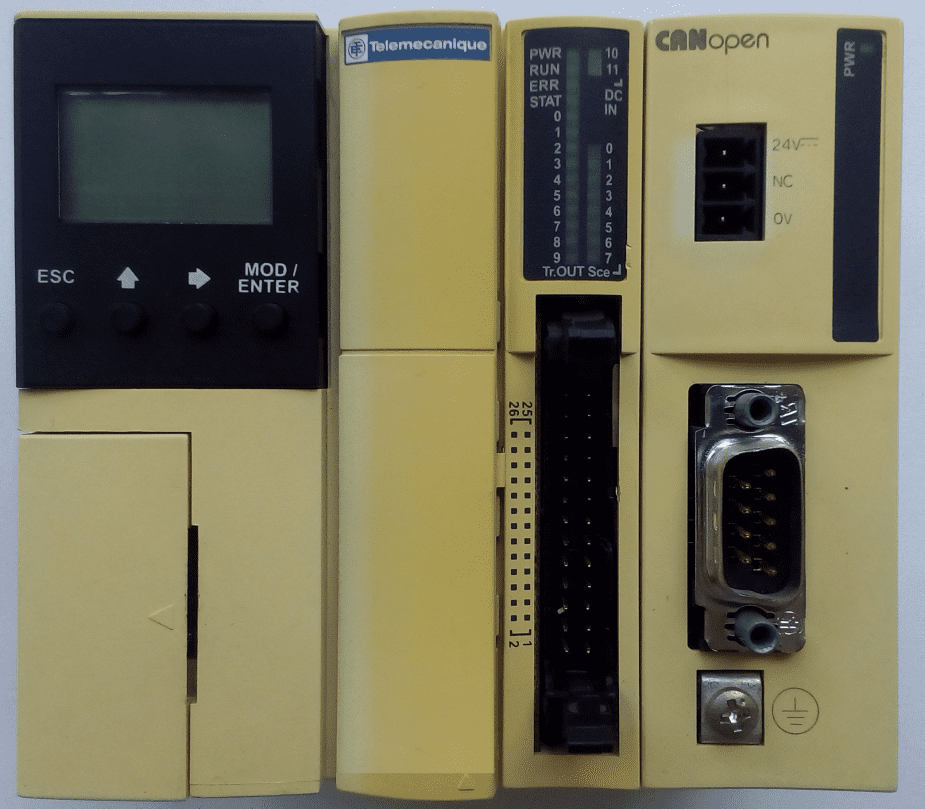
Figure 1 – Appearance of Twido PLC and various expansion modules
Compact base units are available with 10, 16, 24 or 40 I/O channels (I/O).
Modular base units are available with 20 or 40 I/O channels (inputs/outputs).
The number of I/O channels can be increased with the help of expansion modules:
- discrete signal input/output modules or relay modules (15 models);
- analog signal input/output modules (9 models).
The Twido series of modular programmable controllers includes five controllers that differ in processor performance, the number and type of input/output points (20 or 40 points connected via a screw terminal block or HE 10 connector, with relay or transistor (source/receiver) outputs). Any I/O expansion module (consisting of 18 discrete and analog modules) can be connected to the controllers. All modular controllers use a supply voltage of 24 V DC.
Advantages of Twido modular controllers:
- modular design that provides connection from 4 to 7 expansion modules of discrete or analog I/O to the base controller (depending on the model);
- a variety of additional modules, providing a degree of flexibility for large controller platforms. The modules of a memory card, a real-time clock card, a digital display or a serial interface can be connected to the modular TWD LDMA controllers at the same time. In the last two modules, you can add a second serial port adapter RS-485 or RS-232C;
- multiple connection options, such as removable screw terminal blocks, spring type connection or HE 10 connectors, providing easy, fast and safe connection.
An expansion module with a user display terminal is a user executive terminal that can be installed on any base unit as a separate TWDXCPODM expansion module (Fig. 2).
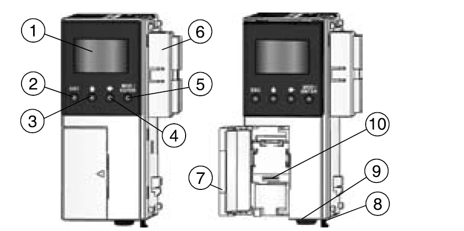
Figure 2 – Appearance of the TWDXCPODM extension module
The user's display terminal provides:
- display of information about the status of the controller;
- control of the base unit;
- control and configuration of application data objects.
The user's display terminal can be in two operating modes:
- display – data indication;
- editing – changing data.
When the TWDNAC485T communication adapter is installed in the serial port 2 connector (pos. 10), it is possible to connect a PLC and an IF via the Modbus protocol.
The module used for connection using the TWDLMDA20DTK base protocols (20-channel base unit) is shown in Figure 3
Figure 3 – Appearance of the TWDLMDA20DTK block
The TWDLMDA20DTK module contains 12 discrete inputs and 8 discrete outputs (8 transistor outputs of the "source" type, Fig. 4).
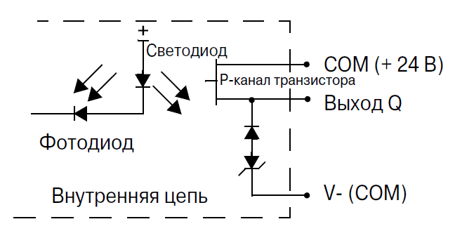
Figure 4 – Diagram of the output transistor output of the "source" type
To connect the digital inputs and outputs, a standard connection scheme recommended by the manufacturer was used, which is shown in Fig. 5.
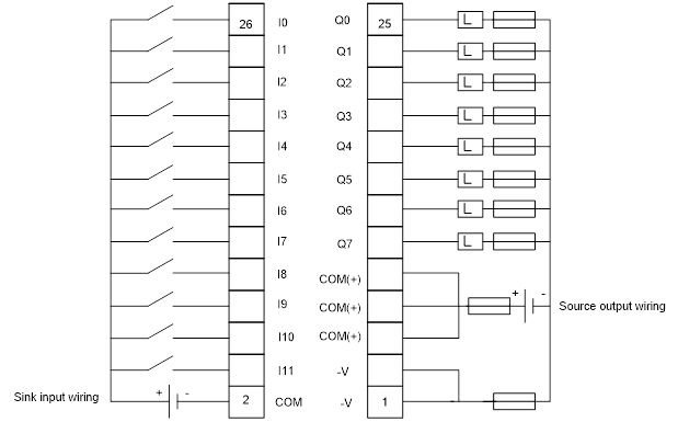
Figure 5 – Connection diagram of the TWDLMDA20DTK modular base unit
Input contacts are located on the left, output contacts are located on the right. The COM and COM(+) contacts inside the module are not electrically connected to each other, in turn, the three COM(+) contacts are electrically connected to each other inside the module and, therefore, there is no need to "power" each of these contacts, it is enough to power one of them. It can also be noted that the contacts –V (which are terminals of positive output voltage) are electrically connected to each other inside the module. If the load circuit needs additional protection, then it is necessary to install fuses of the desired nominal value.
The CANopen bus master module (TWDNCO1M) is used to connect the PLC via the CANopen protocol (Fig. 6).
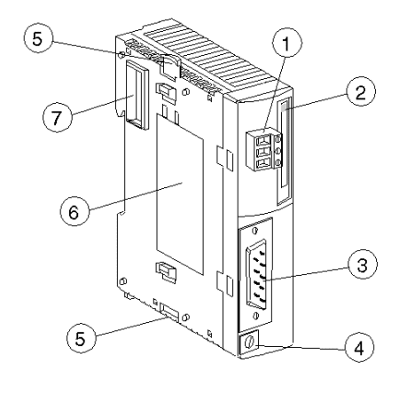
Figure 6 – TWDNCO1M bus master module
2. Altivar 71 frequency converter
The most common method of starting asynchronous motors is directly from the supply voltage line (direct start). This technology is often suitable for a wide range of mechanisms. However, it carries limitations that do not allow it to be used in some applications:
- the current surge at the start may interfere with the operation of other devices connected to the same power line;
- mechanical shock load during the start, which is not permissible for the device or may have a harmful effect on the comfort and safety of the user;
- it is impossible to control acceleration and braking;
- it is impossible to adjust the speed.
Frequency converters have been developed to solve the above problems.
These devices provide the conversion of an alternating current voltage of one frequency into an alternating current voltage of another frequency. The frequency, amplitude and phase of the output voltage are regulated within certain limits. The number of phases of the input and output voltage may also differ.
A typical block diagram of a frequency converter is shown in Fig. 7 IF with a DC link usually do not provide for the need to use an input or output transformer.
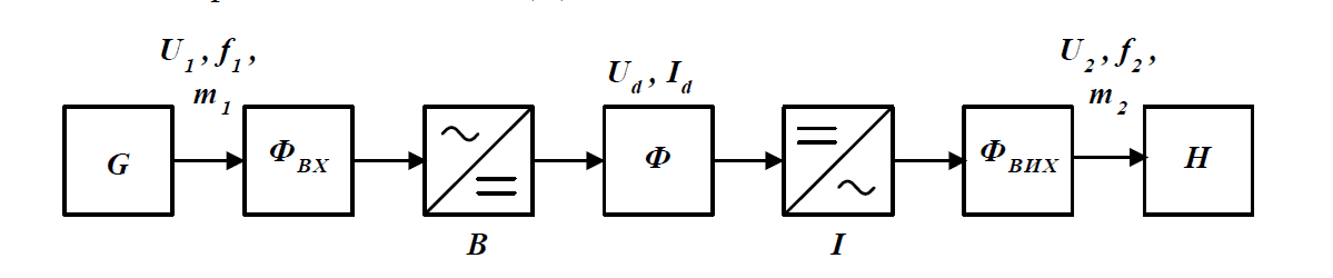
Figure 7 – Block diagram of an IF with a DC link
The block diagram of an IF with a DC link contains:
- m1 – phase AC source (G) with voltage U1 and frequency f1;
- input filter (FVC), to reduce the impact on the network from the side of the IF;
- rectifier (B);
- filter (F) in the DC circuit, which, along with voltage smoothing, has the properties of a voltage source in the input circuit of the inverter;
- m2 –phase inverter(s) with output voltage U2 and frequency f2;
- output filter (FVH) to improve the output parameters of the IF;
- m2 – phase load (H).
The functions of regulating the frequency of the output voltage are performed by the inverter. Regulation of the amplitude of the output voltage (current) is possible in two ways:
- amplitude change of the DC voltage at the input of the inverter;
- pulse, which is carried out by an inverter at a constant DC voltage at the input.
Depending on this, controlled or unmanaged rectifiers are used. The presence of a significant capacity in the DC circuit of an IF with an inverter reduces the rate of voltage change by an order of magnitude, significantly limits the possibilities of amplitude voltage regulation. As a result, in our time, the most widespread are IF using PWM (Fig. 8).
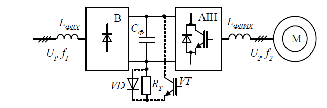
Figure 8 – Block diagram of an IF with a DC link and an AI
Altivar is a line of frequency converters from Schneider Electric. The Altivar 71 frequency converter (the general view of which is shown in Fig. 9) was born as a result of cooperation between two of the world's largest electrical companies Schneider Electric and Toshiba.
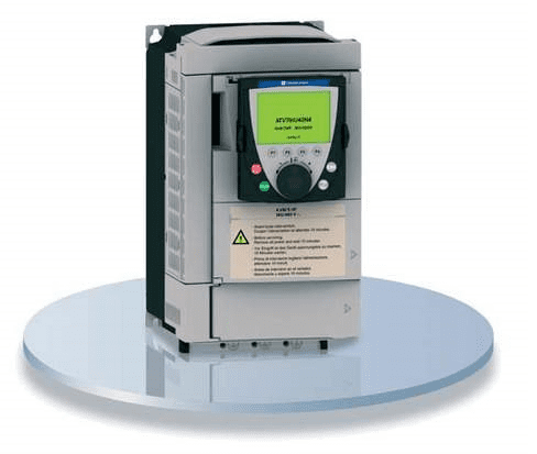
Figure 9 – ATV 71 frequency converter
The latest generation of Altivar 71 converters provides impeccable performance and extensive functionality. This converter is open to all communication networks and adaptable to various applications, taking into account the characteristics of each mechanism.
Characteristics of the Altivar 71:
- starting torque up to 220% Mn;
- flow control in a closed/open system with asynchronous motors – vector;
- speed and torque control function;
- the function of controlling the operation of synchronous motors in an open system;
- overload capacity: 170% for 1 minute, 220% for 2 seconds;
- The Altivar 71 converter can be used with motors from 0.25 kW to 5.5 kW.
The Altivar 71 series of frequency converters meets the most stringent requirements of applications due to the use of a variety of motor control laws and numerous functional capabilities.
The Altivar 71 series is adapted to solve the most complex tasks of an electric drive:
- torque and increased accuracy when operating at very low speed and improved dynamic characteristics with vector flow control algorithms in an open or closed drive system;
- extended output frequency range for high-speed motors;
- parallel activation of motors and special drives using scalar control law;
- accuracy of speed maintenance and energy saving for an open drive with a synchronous motor;
- smooth, shock-free control of unbalanced mechanisms using the power Adaptation System (Energy Adaptation System ENA).
The versatility of the Altivar 71 converter increases the productivity and flexibility of using machines for numerous applications.
Also, this type of IF can be used for lifting and transport equipment tasks.:
- brake control adapted for moving, lifting and turning drives;
- weight measurement;
- lifting with increased speed;
- brake condition monitoring;
- control of the impact of the end-of-stroke limit switches.
3. MODBUS and CANOPEN communication protocols
3.1 MODBUS protocol
Modbus is a communication protocol based on a client-server architecture. Developed by Modicon for use in programmable logic controllers (PLC). It has become a de facto standard in industry and is widely used for the organization of communication of industrial electronic equipment. It uses serial communication lines RS-485, RS-422, RS-232, as well as TCP/IP networks for data transmission. Currently supported by the non-profit organization Modbus-IDA. The Modbus protocol describes a single simple PDU data transmission format, which in turn is included in the complete ADU package. The ADU format varies depending on the type of communication line. There are three protocol modes: Modbus RTU, Modbus ASCII, Modbus TCP. The Modbus RTU protocol assumes one master (requesting) device in the line (master), which can transmit commands to one or more slave devices (slave), addressing them at a unique address in the line. The syntax of the protocol commands allows addressing 247 devices on a single RS-485 communication line (less often RS-422 or RS-232).Some variants of the network topology are shown in Fig. 10.
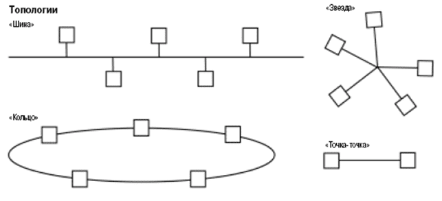
Figure 10 – Network Topologies
MODBUS terms and definitions. The exchange of information takes place on the initiative of the master. It includes a request from the master and a response from the slave. Requests from the moderator are addressed to:
- A specific slave (identified by its number in the first byte of the request frame) (Fig. 11)
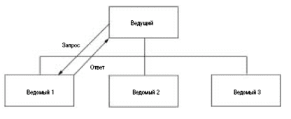
Figure 11 – Request-response
- To all slaves (mailing list) (fig. 12)
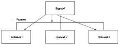
Figure 12 – Mailing list
Distribution commands are always write commands. The slaves do not form responses when receiving such commands.
The Modbus protocol uses frames with standard beginnings and endings. The address is placed at the beginning of the frame.
The initiative of the exchange always comes from the host device. The slaves are listening to the communication line. The master submits a request (a parcel, a sequence of bytes) to the line and enters the listening state of the communication line. The slave device responds to a request sent to its address. The master determines the end of the response message by the time interval between the end of receiving the previous byte and the beginning of receiving the next one. If this interval exceeds the time required to receive two bytes at the specified transmission rate, the reception of the response frame is considered completed.
3.2 CAN protocol
The CAN Field Bus (Controller Area Network) is characterized by high data transfer rates and noise immunity, as well as the ability to detect any errors that occur. It is not surprising that thanks to this, CAN is widely used today in such areas as road and rail transport, industrial automation, aviation, access and control systems. According to the CiA (CAN in Automation) Association, there are currently about 300 million CAN nodes in operation worldwide. In Germany, the CAN bus ranks first in popularity among other field tires.
The general trend in the field of automation is to replace the traditional centralized control system with distributed control by placing intelligent sensors and actuators next to the controlled process. This is caused by an increase in the number of communication wires, an increase in the number of connections, the complexity of error diagnosis and reliability problems. Communication between the nodes of such a system is carried out using a fieldbus. CAN is a communication system for multicontroller systems. Let's take a closer look at the advantages of CAN and the reasons why CAN is becoming more widespread.The CAN protocol has been actively used for more than 20 years, which is very important for such conservative areas as rail transport or shipbuilding. CAN was developed in 1980 by Robert Bosch for the automotive industry. The CAN interface is regulated by the international standards ISO 11898 for high-speed and ISO 11519-1 for low-speed applications. The low cost is determined by a good price/performance ratio, as well as the wide availability of CAN controllers on the market. Reliability is determined by the linear structure of the bus and the equality of its nodes, the so-called Multi-Master Bus, in which each CAN node can access the bus. Any message can be sent to one or more nodes. All nodes simultaneously read the same information from the bus, and each of them decides whether to accept this message or ignore it. Simultaneous reception is very important for synchronization in control systems. The failed nodes are disconnected from the bus exchange.
High noise immunity is achieved due to the suppression of common-mode interference by a differential transceiver, the operation of built-in error detection mechanisms (one undetected error in 1000 years with daily 8-hour network operation at 500 Kbit/s), the repetition of erroneous messages, disconnection of faulty nodes from bus exchange and resistance to electromagnetic interference.
Flexibility is achieved by simply connecting to the bus and disconnecting CAN nodes from the bus, and the total number of nodes is not limited by the lower-level protocol (Fig. 13). The address information is contained in the message and is combined with its priority, according to which arbitration is carried out. During operation, it is possible to change the priority of the transmitted message. It should also be noted the possibility of programming the frequency and phase of the transmitted signal and arbitration, which does not destroy the structure of messages in case of conflicts. At the physical level, it is possible to choose different types of data transmission lines: from a cheap twisted pair to a fiber-optic communication line.
Figure 13 – Signal levels on the CAN bus
Real-time operation becomes possible thanks to the mechanisms of network interaction (multi-master, broadcasting, bitwise arbitration) combined with high data transfer rate (up to 1 Mbit/s), fast response to a transmission request and variable message length from 0 to 8 bytes.
Conclusion
Using these guidelines will help students familiarize themselves with industrial equipment and learn programming in the environment of the Twido programmable logic controller.
In the master's work, the equipment of the Schneider Electric laboratory stand was considered and the Master/Slave system based on Modbus and CANopen protocols was implemented. It offered methodological guidelines that will help to get acquainted with the equipment of the laboratory stand and allow students to get the skills to work with the Twido programmable logic controller.
When writing this abstract, the master's work has not yet been completed. Final completion: June 2023. Full text of the work and materials on the topic can be obtained from the author or his supervisor after the specified date.
References
- Encyclopedia of automated control systems [Electronic resource]. Access mode: http://www.bookasutp.ru/Chapter2_1 ....
- Modbus and Modbus TCP protocols and networks [Electronic resource]. Access mode: http://www.cta.ru/cms/f/435973 ....
- CAN and CANopen: fundamentals [Electronic resource]. Access mode: http://www.fb.asu.in.ua/seti/q_and_/can-i-....
- Technical manual. Programmable Twido controllers. Modular and compact base units – SchneiderElectric.
- Altivar 71 frequency Converter [Electronic resource]. Access mode: http://promalfa.ru/Preobrazo....
- Frequency converter Altivar 71 [Electronic resource]. Access mode: http://elektroautomat.in.ua/subcate ....
- Frequency converters. Altivar 71 – Schneider Electric.
- Twido. Programmable controllers: Software reference guide – SchneiderElectric.
- Altivar 71. User's manual – Schneider Electric.
- GerasimovA.V.,Teryushovi.N.,Titovtseva.S.Programmable logic controllers: textbook-Kazan: publishing house Kazan State Technical University, 2008.-169s.