
Abstract on the topic of the final work
Pollution process
During the operation of the steam generator, contamination of the external heating surfaces occurs. Slag deposits are possible on the screens and screens of a furnace operating on pulverized solid fuel. These deposits are formed at a gas temperature at the outlet of the furnace, higher than the softening temperature of the ash, as well as in the high-temperature zones of the furnace with unsatisfactory aerodynamic organization of the furnace process in cases where the molten ash particles that do not have time to cool and solidify, are carried by the flow of gases onto the walls of the furnaces and pipes of the screens [1]. Usually, slagging begins in the gaps between the screen pipes, as well as in stagnant zones and sections of the furnace [2].
If the temperature of the combustion medium in the zone of formation of slag deposits is below the temperature of the beginning of ash deformation tA, then the outer layer of slag consists of hardened particles. With an increase in temperature, the outer layer of slag can melt, which contributes to the adhesion of new particles and progressive slagging. At an ambient temperature above the point of the beginning of the liquid-melting state tC, the outer layer of slag will melt and there will be no further growth, since the slag will drain from the walls of the furnace. In this mode, studded screens of furnaces with liquid slag removal work.
Slag reduces the heat absorption of the heating surfaces located in the furnace and increases the temperature of the combustion products at the furnace outlet, which can lead to disruption of the normal hydrodynamic operation of screens and screens. In the area of the superheater, if the gas temperature is below tA, compacted deposits of solid ash particles [3] take place. Strong deposits are formed when there is free CaO lime in the fuel ash, which, when combined with SO3, forms calcium sulfate, which binds ash particles between itself and the surface of the pipes.
Loose free-flowing deposits of small fractions of ash are formed in the economizer, and the growth of the polluting layer is accompanied by the destruction of its larger particles, as a result of which a dynamic equilibrium and a steady state of the polluting layer are established.
A sticky bonded deposit may form in the low temperature zone. The transition from loose to viscous deposits at low temperatures, where moisture condensation can occur, is due to the fact that gypsum, a substance with astringent properties, is formed as a result of wetting the ash with sulfuric acid.
Ash deposits on convective heating surfaces are formed mainly on the aft surfaces of the pipes, and at low flow rates - on their frontal surfaces. Larger ash particles settle on the frontal surfaces, smaller ones, bending around the pipes and getting into the vortex zone, settle on the aft surfaces.
The amount of deposits on convective heating surfaces depends on the flow rate of combustion products, the geometric characteristics of the heating surface and the physical properties of the ash.
The rate of gas flow significantly affects polluting deposits. The number of contacts with pipes of small particles increases in proportion to the flow velocity, and the destructive action of large particles increases in proportion to this velocity to the third degree. As a result, with an increase in the flow rate, the dynamic equilibrium between the processes of ash settling and the destruction of its settled layer occurs at smaller flow sizes.
The diameter of the pipes, the pitch between the pipes, as well as the order of their arrangement - in-line or staggered - significantly affect the contamination of pipes. Reducing the diameter of pipes and the longitudinal pitch in staggered bundles significantly reduces their contamination. Corridor bundles of pipes are more prone to pollution than staggered ones.
Reducing the size of the ash particles increases the fouling of the convective heating surfaces. However, particles with a size of less than 20 microns practically do not settle on the pipes. Large ash particles have a destructive effect on the layer of ash deposits. The ash content of the fuel does not affect the thickness of the contaminants. Upon reaching a certain thickness of contamination, ash no longer settles on contaminated pipes. The thickness of sticky contaminants in the low temperature region depends on the ash content of the fuel and the characteristics of the ash and progresses with time.
Due to pollution of convective heating surfaces, heat transfer conditions worsen and their aerodynamic resistances increase. As a result, the temperature of the flue gases rises, the heat losses with the flue gases and the consumption of electricity for traction increase. For normal and reliable operation of the boiler, the heating surfaces must be kept clean.
Cleaning process
During the operation of the boiler, steam and steam-water blowing, as well as vibration cleaning are used to clean the screen heating surfaces, and steam and steam-water blowing, vibration, shot and acoustic cleaning are used for convective heating surfaces.automatic cleaning or self-blowing [4].
Steam blowing and shot cleaning are the most common. For screens and vertical superheaters, vibration cleaning is the most effective. Radical is the use of self-blown heating surfaces with a small diameter and pipe pitch, in which the heating surfaces are continuously kept clean.
Steam blowing. Cleaning of heating surfaces from contamination can be carried out due to the dynamic action of jets of water, steam, steam-water mixture or air[5]. The effectiveness of jets is determined by their range[6].
The water jet has the greatest range and thermal effect, which contributes to the cracking of the slag. However, water blowing can cause supercooling of the screen pipes and damage to their metal. The air jet has a sharp decrease in speed, creates a small dynamic pressure and is effective only at a pressure of at least 4 MPa.
The use of air blowing is hampered by the need to install high-capacity and high-pressure compressors.
Blowing with saturated and superheated steam is the most common. The steam jet has a small range, but at a pressure of more than 3 MPa, its action is quite effective [7]. At a steam pressure of 4 MPa in front of the blower, the dynamic pressure of the jet at a distance of about 3 m from the nozzle is more than 2000 Pa.
To remove deposits from the heating surface, the dynamic pressure of the jet should be approximately 200-250 Pa for loose ash deposits, 400-500 Pa for compacted ash deposits, 2000 Pa for melted slag deposits.
Blowers. The structural diagram of the blower is shown in fig. 1.
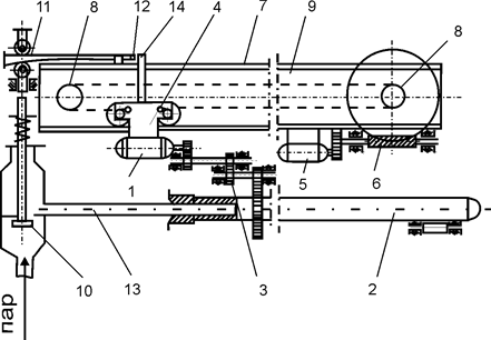
Figure 1 - Blower
Where:
- 1, 5 - electric motors;
- 2 - blow pipe;
- 3, 6 - reducer;
- 4 - caret;
- 7 - monorail;
- 8 - asterisk;
- 9 - infinite chain;
- 10 - shut-off valve;
- 11 - thrust with a wedge;
- 12 - lever;
- 13 - fixed steam pipeline;
- 14 - rod.
Blower includes:
- electric motor 1 mounted on carriage 4;
- reducer 3, designed to rotate blowpipe 2;
- electric motor 5 and gearbox 6, mounted on a monorail 7, designed for translational movement of blower tube 2;
- a mechanism for translational movement of the blower tube, consisting of a carriage 4, which moves along the shelves of the monorail 7, sprockets 8 and an endless chain 9;
- shut-off valve 10, which automatically opens steam into the blowing pipe after it reaches the blowing position; a mechanism that controls the shut-off valve 10 and consists of a rod with a wedge 11 and a lever 12.
The blast pipe is connected by means of a stuffing box to a fixed steam line 13, which supplies steam to it from a shut-off valve. I-beam monorail 7 carries all of these mechanisms, and is itself attached to the boiler frame. Upon receiving a pulse from the previous blower that has completed its work, the starter turns on electric motors 1 and 5. This turns on the signal lamp located on the blower program control panel. Carriage 4, moving along the monorail, introduces blower tube 2 into the flue. When the blast pipe reaches the blowing position, the rod 14, acting on the lever, entrains the wedge 11 with the help of a rod, which, through the pusher, depresses the shut-off steam valve, which opens the access of steam to the blowing pipe. The steam from the blower pipe exits through the nozzles, blowing over the heating surface.
During the translational-rotational movement of pipe 2, blowing is carried out along a helical line. After the blower pipe is completely inserted into the gas duct, the pin mounted on the drive chain 9, acting on the limit switches of the electric motor 5, switches the device to reverse. In this case, the heating surface is blown in the same way as when the blower pipe moves inside the gas duct.
Before the nozzle head is removed from the gas duct, the rod 14, acting through the lever 12 on the wedge 11, will bring it to its original position, and the shut-off steam valve will close under the action of the spring, stopping steam from entering the blowing pipe.
When the blower pipe returns to its original position, the pin mounted on the drive chain 9, acting on the limit switches, turns off the electric motors 1 and 5, and the next device in the circuit receives an impulse to turn on [8].
The area of operation of the blower is up to 2.5 m, and the depth of entry into the furnace is up to 8 m. The blowers are placed on the walls of the furnace so that their area of operation covers the entire surface of the screens.
Blowerss for convective heating surfaces have a multi-nozzle tube, do not move out of the flue and only rotate. The number of nozzles located on both sides of the blowing pipe corresponds to the number of pipes in the row of the blown heating surface [9].
Swinging tube blowers are used for regenerative air heaters. Steam or water is supplied to the blower pipe, and the jet flowing from the nozzle cleans the air heater plates. The blower pipe is rotated at a certain angle so that the jet enters all cells of the rotating air heater rotor. To clean the regenerative air heater of solid fuel steam generators, steam is used as a blowing agent, and alkaline water is used as a blowing agent for fuel oil steam generators. Water washes well and neutralizes sulfuric acid compounds present in sediments.
Steam-water blowing. The working agent of the blower is water from the steam generator or feed water.
The apparatus consists of nozzles installed between the tubes of the screens. Water is supplied to the nozzles under pressure, and as a result of the pressure drop when passing through the nozzles, a steam-water jet is formed from it, directed to opposite sections of the screens, scallops, and screens. The high density of the steam-water mixture and the presence of water that has not evaporated in the jet have an effective destructive effect on slag deposits, which are removed to the lower part of the furnace.
Vibration cleaning. Vibration cleaning is based on the fact that when the pipes vibrate at a high frequency, the adhesion of deposits to the metal of the heating surface is broken.
Most effective is vibration cleaning of freely suspended vertical pipes, screens and superheaters. For vibration cleaning, electromagnetic vibrators are mainly used (Fig. 2).
Superheater pipes and screens are attached to a rod that extends beyond the lining and connects to the vibrator. The draft is cooled by water, and the place of its passage through the lining is sealed. The electromagnetic vibrator consists of a body with an anchor and a frame with a core, fixed by springs. Vibration of the cleaned pipes is carried out due to strokes on the rod with a frequency of 3000 beats per minute, the oscillation amplitude is 0.3-0.4 mm.
Shot cleaning. Shot cleaning is used to clean convective heating surfaces in the presence of compacted and bonded deposits. Cleaning occurs as a result of using the kinetic energy of iron shots falling on the cleaned surfaces with a diameter of 3-5 mm. Spreaders are placed in the upper part of the convective shaft of the steam generator, which evenly distribute the shot over the cross section of the gas duct. When falling, the shot knocks down.
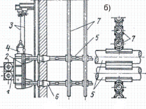
Figure 2 - Vibratory device for cleaning vertical pipes
Where:
а — side view;
b - pairing of vibrating bar with heated pipes, top view;
1 - vibrator;
2 - slab;
3 - rope;
4 - counterweight;
5 - vibrating bar;
6 - sealing the passage of the rod through the lining;
7 - pipe.
The ash that has settled on the pipes, and then together with it, is collected in bunkers located under the mine. From the bunkers, the shot along with the ash enters the collection bin, from which the feeder delivers them to the pipeline, where the mass of ash with the shot is picked up by air and carried out to the shot trap, from which the shot is again fed through the sleeves to the spreaders, and the air, together with the ash particles, is sent into a cyclone where they separate. From the cyclone, air is discharged into the flue in front of the smoke exhauster, and the ash that has settled in the cyclone is removed into the ash removal system of the boiler plant.
Shot transport is carried out according to the suction or discharge scheme. With a suction circuit, a vacuum in the system is created by a steam ejector or a vacuum pump. With the injection scheme, the transporting air is supplied to the injector from the compressor. For the transport of shots, an air speed of 40 - 50 m / s is required.
Recently, shot cleaning is practically not used. This is due to the deformation of the heating surfaces and the relatively low efficiency.
References
- Гаврилов А.Ф., Малкин Б.М., Загрязнение и очистка поверхностей нагрева котельных установок / А.Ф. Гаврилов, Б.М. Малкин // М.: Энергия – 1980 г., 328 с.
- Загрязнение поверхностей нагрева [Электронный ресурс] - https://infopedia.su/18xe121.html
- Попова Е. С. Влияние загрязнений на работу поверхностей нагрева при сжигании твердого топлива на примере плоской стенки / Е. С. Попова ; науч. рук. А. Ю. Долгих // Интеллектуальные энергосистемы : труды IV Международного молодёжного форума, 10-14 октября 2016 г., г. Томск : в 3 т. — Томск : Изд-во ТПУ, 2016. — Т. 1. — [С. 213-216].
- Технологии очистки паровых котлов [Электронный ресурс] - https://www.rosteplo.ru/Tech_stat/stat_shablon.php?id=3232
- Эксплуатация энергетических блоков - очистка поверхностей нагрева котлов от наружных загрязнений [Электронный ресурс] - https://leg.co.ua/arhiv/generaciya/ekspluataciya-energeticheskih-blokov-31.html
- Очистка и пассивация теплоэнергетического оборудования ТЭС [Электронный ресурс] - https://studopedia.ru/9_39738_glava-.html
- ПОВЕРХНОСТИ НАГРЕВА КОТЕЛЬНЫХ УСТАНОВОК [Электронный ресурс] - https://foraenergy.ru/4-3-23-poverxnosti-nagreva-kotelnyx-ustanovok/
- ВНУТРЕННЯЯ ОЧИСТКА ПОВЕРХНОСТЕЙ КОТЛОВ [Электронный ресурс] - https://msd.com.ua/remont-parovyx-kotlov/vnutrennyaya-ochistka-poverxnostej-kotlov/
- Виды химических очисток оборудования ТЭС и АЭС [Электронный ресурс] - https://tesiaes.ru/?p=10402