
Abstract
Attention! At the time of writing this abstract, the master's work has not been completed. The estimated completion date is May 2022. The full text of the work, as well as materials on the topic, can be obtained from the author or his supervisor after the specified date.
Content
- Introduction
- 1. Theme urgency
- 2. Goal and tasks of the research
- 3. Overview of research and development
- 3.1 Overview of international sources
- 3.2 Overview of national sources
- 3.3 Overview of local sources
- 4. Disadvantages of graphics tools
- 5. CAD tools for design automation
- 5.1 API in CATIA
- 5.2 Macros
- 6 Patterns in programming languages
- Conclusion
- References
Introduction
CATIA has become widespread in industry and is used by various large manufacturers in the design of vehicles, installations, machines.
Innovations in CAD software continue to improve the quality of design by increasing accuracy and reducing design errors. CAD software is also able to improve the technology of creating geometric objects by creating templates.
1. Theme urgency
When creating models, a standard set of bodies is often used, in which only parameters such as length, width, height, diameter, etc. change. To simplify and reduce the design time of complex parts, it is advisable to create templates that are used for all or part of the models being created.
In this regard, the expansion of the functionality of the geometric design subsystem in CATIA CAD should improve the work of the designer by reducing the time spent on creating geometric objects when designing complex objects and have a user-friendly interface.
2. Goal and tasks of the research
The purpose of the work is to design and develop an application that simulates the construction of simple geometric objects using software templates.
The main objectives of the study:
- analysis of possible ways to create templates in CATIA CAD;
- analysis system tools for design automation;
- presentation general methods of solving the problem;
- development of a template structure for the synthesis of geometric objects;
- justification of the requirements for the system being created, as well as for the input parameters entered by the user;
- description of the algorithm of the program;
- implementation of the template structure for the synthesis of geometric objects;
- representation of the organization of logical inference;
- investigation of the effectiveness of the use of template technology.
The object of the study: implementation of the CATIA CAD add-on.
Subject of research: aggregation of applied software interfaces graphics and intelligent design techniques in CAD CATIA.
3. Overview of research and development
3.1 Overview of international sources
Katzenbach A., Bergholz W., Rolinger A. in their work Knowledge-based Design — An Integrated Approach
[1] represent a methodological concept (templates) that standardizes the design process and its subsequent processes. The results of the accompanying psychological study of user acceptance are also presented and discussed.
Gruber T. in his article The role of common ontology in achieving sharable, reusable knowledge bases
[2] presents a strategy for creating libraries of shared, reusable knowledge in which shared ontologies play a central role as a knowledge link construct. And also identifies problems in the design of shared ontologies.
In the work of the authors Harshadeep J., Pooja G., Shraddha S., Sonu M. Automated CAD Modelling of Mechanical Components
[3] It has been successfully demonstrated how geometric CAD modeling can be fully automated, reducing the probability of error and increasing the overall efficiency of the design process.
3.2 Overview of national sources
In the work «Integration of the computer graphics module into the system CATIА» Barladyan B.H., Deryabin N.B., Shapiro L.Z. [4] consider two approaches to integrating realistic image synthesis and optical modeling systems into computer-aided design systems. An approach providing partial automation of this integration is proposed.
Dubovik S.E. and Soshnikov D.V. [5] are engaged in the use of semantic networks extended by trees AND/OR for the representation of structural and dynamic knowledge in intelligent systems. In this article, they propose a model for the representation of structural-dynamic knowledge using semantic networks extended by trees AND/OR. Such a model combines structural-static and dynamic knowledge in a single graphical formalism and makes it possible to determine a unified logical inference mechanism based on the proposed representation.
3.3 Overview of local sources
The topic of intelligent design techniques in modern CAD is of interest to the masters of Donetsk National Technical University.
I.O. Zimonin was engaged in research of methods of development of graphic editors in CAD systems on the example of CAD pipelines [6]. In his work, he analyzed the principles of creation, composition and structure of CAD, existing software products, identified a strategy for further development of an optimal set of methods for building a CAD system in pipeline CAD. And also performed an assessment of the effectiveness of the selected complex and justification of the selected methods and technologies for the development of an up-to-date modern system.
In the master's thesis O.V. Malyavki«Research of ways of organizing the construction of an instrumental intellectual shell for the design of complex objects based on expert techniques» [7] the analysis of the existing CAD construction tools has been carried out, the existing algorithms have been improved. An assessment of their effectiveness was carried out and a toolkit for automating the creation of problem–oriented CAD systems was built with their help.
Also K.V. Rzhevsky was doing a similar study. The topic of his work: "Research of methods for creating intelligent add-ons over graphic editors on the example of CAD pipelines" [8].
V.A. Bolotovа was engaged in tools for creating knowledge bases based on the ontology system [9]. A.A.Fomenko researched tools for creating intelligent CAD systems based on semantic productions defined over formal grammars [10].
4. Disadvantages of graphics tools
Despite the versatility and large tools for creating drawings, CAD CATIA still has its drawbacks.
First of all, it is a difficult search for the necessary tool to create objects in a sketch. This is due to the fact that all toolbars in the program cannot be placed simultaneously in the window of working with the program.
Updating an existing sketch can be difficult. You should reassign, for example, all radii, even if they have shifted slightly.
CATIA implements complex mouse operations. For example, increasing the size of a drawing on the screen is not available by scrolling the mouse wheel. Objects are rotated by clicking the mouse on a certain area.
It is worth noting that it is not possible to import models of other types created in other programs in CATIA. Moreover, when importing objects of the same type into CATIA, not all functions for working with such objects are available, but only a part of them [11].
5. CAD tools for design automation
For design automation in CAD, CATIA uses both language tools that interact with the system and can complement it, as well as built-in system tools. They are able to facilitate the work of the designer when working with sketches in CAD.
Consider the programming languages used for design automation in CATIA CAD.
CATIA V5 CAD running on Windows can be automated using any application that can connect to the Windows Component Object Model (COM), including VBA (Excel, Word, CATIA, etc.), VBScript, JavaScript, Visual Basic 6.0, Microsoft Developers Studio.NET and others. For CATIA V5 running on UNIX, emulators allow you to run VBScripts scripts without tools to create an interface.
Applications for CATIA can be written as:
1) macros *.catvba, scripts*.CATScript;
2) standalone applications compiled in *.exe-file;
3) in the form of applications, plugins, using CAA-RADE - on С++.
5.1 API in CATIA
To create standalone applications, you can use any programming language, for example, VB6, C#, Delphi. At the same time, interaction with CATIA occurs as with a COM object, and API capabilities are used for this.
API - is a set of definitions and protocols for creating and integrating application software. API means Application Programming interface.
API is used in CAD for:
1) automation of drawings;
2) simplify the creation and editing of drawings.
API makes it possible to fully control the source code, promptly correct errors and increase functionality. Developers of CATIA, NX, Creo Elements/Pro, Solid Edge, Autodesk Inventor, think3, COMPASS-3D use this in their systems.makes it possible to fully control the source code, promptly correct errors and increase functionality. Developers of CATIA, NX, Creo Elements/Pro, Solid Edge, Autodesk Inventor, think3, COMPASS-3D use this in their systems.
The new development, codenamed CNext, became known worldwide in 1998 under the name CATIA V5. It has an open architecture — you can insert your own developments and programs into it (for example, thermal calculation, etc.), functions necessary to expand the capabilities of specialized modules [12].
Using programming in the languages VB CATIA, Java, C++, VBA, Basic Script allows you to automate the entire design process. The API for CATIA is called "CAA" - short for Component Application Architecture. This API is written in C++. CATIA has other APIs based on Microsoft Visual Basic and Java, but they are not as full-featured and not as flexible as the CAA C++ API. Instead of the outdated Fortran, C++ was chosen as the programming language, and the geometric core of the new system was named CGM – CNext/CATIA Geometric Modeler [13]. The features of working with the application programming interface are prescribed in the technical documentation. It also indicates which values must be supplied to the input of a particular function in order to get correct values at its output, according to the purpose of this function.
Thus, the API allows you to abstract from the implementation of individual program blocks when developing applications. This concept is most clearly revealed by the example of a black box (Figure 1).
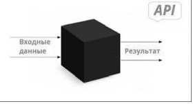
Figure 1 – «Black Box»
Physically, API functions are represented as a separate software module that is dynamically connected from the outside to the main project in the DLL library format [14].
5.2 Macros
If the task needs to be performed repeatedly, you can use a macro to automate the task. A macro is a set of functions written in a scripting language that are grouped into a single command to automatically perform the requested task. Macros use programming, but you don't have to be a programmer or have programming knowledge to use them. Macros are used to save time and reduce the likelihood of human error by automating repetitive processes, standardizing, increasing efficiency, expanding CATIA capabilities and optimizing tasks.
All scripting languages (VBScript, CATScript and VBA) interact with CATIA via dynamically linked libraries (DLLs). A DLL file is a type of file that contains instructions that can be invoked by other programs to perform certain actions. Thus, several programs can share the capabilities programmed in the same file, and even do it at the same time. Unlike executable programs, such as programs with the EXE extension, DLL files cannot be run directly, instead they must be called by other already running code.
CATIA stores macros in macro libraries. They can be stored in one of three places: in folders (VBScript and CATScript macros), in project files, or in documents such as CATParts, CATProducts and CATDrawings. CATIA allows you to use only one macro library at a time [15].
CATIA allows you to use several different scripting languages to write macros. Generally speaking, scripting languages are easier and faster to code than structured, compiled languages like C, but they are slightly slower than compiled languages. But, of course, speed is not a problem, since macros usually use only a few lines of code.
VBScript - is a subset of the Visual Basic Programming language (VBA). All VBScript elements are present in VBA, but some VBA elements are not implemented in VBScript. Scripting languages are easier and faster to code than more structured, compiled languages like C+ and C++. The CATIA-specific code is saved as a file.CATScript.
CATScript - эit is a portable version of VBScript developed by Dassault Systemes. CATScript is very similar to VBScript. It is a sequential scripting language without a graphical user interface that can be written using simple programs. It has the same advantages and disadvantages as VBScript.
Visual Basic for Applications (VBA) is another subset of Visual Basic. Visual Basic for Applications, abbreviated VBA, is a scripting language that is embedded in a separate Microsoft application, such as Excel or Access. Using VBA, you can create macros or small programs that perform tasks in a Microsoft application. VBA has its own editor, debugger and help object viewer. All versions of CATIA after V5R8 support macros developed using VBA [16].
6. Patterns in programming languages
Knowledge-based engineering templates are "intelligent" models or functions that can store design ideas and knowledge about product creation. They can then recover the knowledge by adapting it to design contexts, i.e. environments in which the template is used, such as a car assembly model or an airplane wing model.
Templates are parametric models created using KBE elements such as formulas, rules, and automation. KBE elements allow you to change the contents of the template (for example, configuration or geometry) in accordance with the specified input data.
The process of calling a KBE template in a specific context is called "instantiation" and leads to the creation of a copy of the template that will be placed in the specified context. This copy is called an "instance". According to the input data, the instance will be configured to match the specific context. Instances have a separate lifecycle, which means that any changes made to the template definition will not change its existing instances [17].
CAD systems by the method of organizing a dialogue with the user using[15]:
The template lifecycle is an iterative process. Before deploying a template to end users, it must be developed based on requirements, tested and deployed with the necessary documents (documentation, configuration tables, accompanying CAD models, etc.). After deployment, templates are maintained and updated to correct possible errors or add new features [18].
The template lifecycle diagram is shown in Figure 2.
Рисунок 2 – Template Lifecycle
(animation: 13 frames, 14 kilobytes)
The main drivers of almost all patterns in design automation are the following factors: reliability, clarity, flexibility, maintainability, stability, etc.
Thus, the better the design pattern is created, the longer its life cycle lasts.
Conclusion
In the course of this work, the analysis of the system tools for design automation and possible ways to create templates in CATIA CAD and the analysis of the system tools for design automation were carried out.
According to the results of the study, it can be concluded that the topic of the master's thesis is relevant and little studied, therefore this area is a promising area for research and development.
Automation of the design process is an urgent task, as it significantly reduces the development time of the final product.
References
- Katzenbach A., Bergholz W., Rolinger A.: Knowledge-based design – an integrated approach, in: S.B. Heidelberg (Ed.), The Future of Product Development, 2007, pp. 13-22.
- Gruber T. “The Role of Common Ontology in Achieving Sharable, Reusable Knowledge Bases.” KR, 1991.
- Harshadeep J., Pooja G., Shraddha S., Sonu M. (2017). Automated CAD Modelling of Mechanical Components. 10.2991/iccasp-16.2017.37.
- Барладян Б.Х., Дерябин Н.Б., Шапиро Л.З. Интеграция модуля компьютерной графики в систему CATIA // Новые информационные технологии в автоматизированных системах. 2013. №16.
- Дубовик С.Е., Сошников Д.В. Использование семантических сетей, расширенных деревьями И/ИЛИ для представления структурно-динамических знаний в интеллектуальных системах [Электронный ресурс] // Сборник научных трудов МАИ — Режим доступа: Ссылка.
- Исследование методов разработки графических редакторов в CAD-системах на примере САПР трубопроводов [Электронный ресурс] // Портал магистров ДонНТУ. — Режим доступа: Ссылка.
- Исследование способов организации построения инструментальной интеллектуальной оболочки для проектирования сложных объектов на базе экспертных методик [Электронный ресурс] // Портал магистров ДонНТУ. — Режим доступа: Ссылка.
- Исследования методов создания интелектуальных надстроек над графическими редакторами на примере САПР-трубопроводов [Электронный ресурс] // Портал магистров ДонНТУ. — Режим доступа: Ссылка.
- Инструментальные средства создания баз знаний на основе системы онтологий [Электронный ресурс] // Портал магистров ДонНТУ. — Режим доступа: Ссылка.
- Инструментальные средства создания интеллектуальных САПР на основе семантических продукций, определенных над формальными грамматиками [Электронный ресурс] // Портал магистров ДонНТУ. — Режим доступа: Ссылка.
- Бондаренко Е.С. Исследование API САПР CATIA V5 и перспективы развития создания приложений в ней [Электронный ресурс] / Е.С. Бондаренко, А.В. Григорьев // Материалы студенческой секции X Международной научно-технической конференции «Информатика, управляющие системы, математическое и компьютерное моделирование» (ИУСМКМ - 2019). – Донецк: ДОННТУ, 2019. –с. 105-109.
- Зитен Д. Программирование макросов CATIA V5 с помощью скрипта Visual Basic, McGraw-Hill, 2013.
- Ledermann C., Hanske C., Wenzel J., Ermanni P., Kelm R. ”Associative parametric CAE methods in the aircraft pre-design”, Journal of Aerospace Science and Technology, Vol. 9, Issue 7, October 2005, pp. 641-651, Elsevier.
- Басов К.А. CATIA V5. Геометрическое моделирование. – М.: ДМК Пресс, 2008. – 272 с., ил. (Серия «Проектирование»).
- Ходосов В.В. Основы создания деталей в САПР CATIA V5: учебное пособие / В.В. Ходосов; Балт. гос. техн. ун-т. – СПб., 2019. – 66 с.
- Koh J. CATIA V5 Design Fundamentals A Step by Step Guide. – ONSIA.
- Малюх В.Н. Введение в современные САПР, М.: ДМК Пресс, 2010.
- Harris T. CATIA V5 R12. 2004.