1. ANALYSIS OF METHODS, MODELS AND ALGORITHMS FOR ENSURING THE AVAILABILITY OF SERVICES IN COMMERCIAL MOBILE ACCESS NETWORKS
1.1. Load balancing methods in mobile communication networks
1.1.1. Load balancing Scenarios and goals
Due to the random distribution of subscribers and exponentially growing demand for wireless data transmission services, mobile networks face problems caused by uneven load distribution.Figure 1.1 demonstrates the scenario of uneven load distribution.
Structure and scope of work. The Master's thesis consists of an introduction, seven sections and a conclusion, which are set out on 101 pages of text illustrated with 53 drawings. The work contains 5 tables, 1 appendix and a list of references from 21 sources.
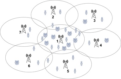
Fig. 1.1–Uneven load distribution scenario.
As shown in Figure 1.1, BS 1 (cell 1) is surrounded by six neighboring cells. Usually, operators determine the BS coverage area and pre-allocate spectral resources based on their usual load, which is estimated based on population density. Nevertheless, during social events (music concert, rally, football match), thousands of users gather in a small area, for example, cell 1 of Figure 1.1. The traffic generated by these users often exceeds the bandwidth from 1. Thus, cell 1 becomes overloaded, at a time when the load created by users in neighboring cells is negligible. This is one of the examples when mobile networks are subjected to uneven load distribution.
As shown in Figure 1.1, BS 1 (cell 1) is surrounded by six neighboring cells. Usually, operators determine the BS coverage area and pre-allocate spectral resources based on their usual load, which is estimated based on population density. Nevertheless, during social events (music concert, rally, football match), thousands of users gather in a small area, for example, cell 1 of Figure 1.1. The traffic generated by these users often exceeds the bandwidth from 1. Thus, cell 1 becomes overloaded, at a time when the load created by users in neighboring cells is negligible. This is one of the examples when mobile networks are subjected to uneven load distribution.
The impact of uneven load distribution is reflected in various aspects. An excessively loaded cell, for example, in this case cell1, may reject access requests from new users, may not provide service to users with the necessary QoS [28]. And the spectrum of neighboring cells, such as cell 4 cell 5, is not used enough.
Load balancing is one of the functions of radio resource management. Load balancing can reduce the negative impact of uneven load distribution and improve network performance. The generally accepted performance indicators for evaluating the load balance scheme are:
- the probability of blocking calls;
- frequency of failed transmission (for load balancing schemes based on movement);
- load reduction in an overloaded cell.1.1.2.
1.1.2 Generalized load balancing process
The overall load balancing process includes three stages. A network controller, for example, a mobile switching center in 2G networks, identifies an overload cell (hot cell), in accordance with its load conditions. The hot cell then selects the less loaded neighboring cells as its partners. After selecting a partner, the overloaded cell adopts a specific load balancing scheme to share the load with partners, for example, redistributing free channels from partners or moving the load to its partners, created by users at the edge of the cell. Figure 1.2 shows an example of uneven load distribution.
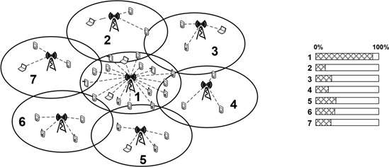
Fig. 1.2 an example of uneven load distribution between cells: a) terminal distribution; b) cell load
Consider the stages of the overall load balancing process.
1) Load rating. Load estimation is an important step for load balancing schemes. Cell loading is formulated as [3gpp10b]:
The number of carrier frequencies involved in the cell.
L = _______________________________________________ (1.1)
Total number of carrier frequencies in a cell
According to (1.1), the load of the cell is in the range from 0% to 100% (0% < L< 100%). The load of any cell can be divided into different levels here:
- Congestion: the traffic created by users is equal to or exceeds the volume of the cell, namely, all carriers are used in the cell.
- excessive load: a large number of carriers are used in the cell, namely, 100% > L > LHL. LHL is the threshold for detecting an overloaded cell. The LHL value is 70% [33].
* Light load: a small number of carrier frequencies are used in the cell, namely, L < LHL.
Note that equation (1.1) is an example of calculating the load of a cell [16]. The formula for calculating the cell load is based on a specific multiple access technology and a load balance scheme. In addition, different balance schemes may have different methods or threshold values for determining the load level of the cell.
Load balancing can be triggered when the cell load is equal to or higher than the lhl threshold of overloading. In this case, a cell with a load higher than LHL is defined as a hot cell. For example, in Figure 1.2, cell 1 is a hot cell whose load level triggers load balancing.
2) Choosing a partner. The second step of balancing the load of cell 1 is to select one or more adjacent cells (for example, cell 2 cell 3... cell 7 in Figure 1.2) as partners. If cell 1 chooses an acceptable load level of the neighboring cell as its partner, then it may become overloaded after load balancing, which will entail a high probability of blocking calls. Many conventional load balancing schemes, such as [39] [34] [29] [26] [38], this step is based on the load of the neighboring cell.
3) channel reallocation or load shifting. After selecting a partner/s, the hot cell performs a special balance scheme to share the load with the selected partners. In general, conventional load balancing schemes can be divided into two categories: channel redistribution schemes (Figure 1.3) and load displacement schemes (Figure 1.4).
The main idea of the channel redistribution scheme is that a hot cell borrows part of the free spectrum from neighboring cells. Channel reallocation schemes are suitable for mobile networks with a frequency reuse factor greater than (FRF) 1, where neighboring cells use a different frequency spectrum.
As shown in Figure 1.4 (a), cell 1, 4 and 5 use a spectrum that does not overlap to serve users. When cell 1 is overloaded, it can take up free frequency resources from cells 4 and 5. As a result, cell 1 can handle more new calls from users and provide a better quality of service
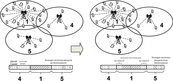
Fig. 1.3Load balance based on channel redistribution
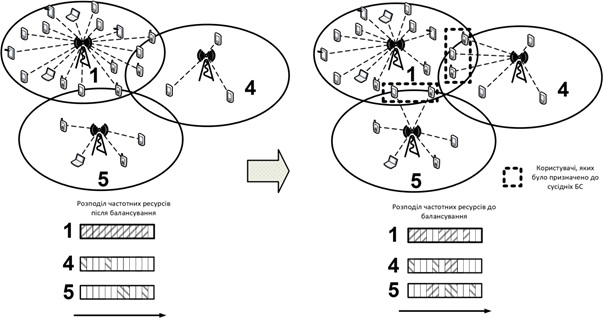
Fig. 1.4Load balance based on load displacement
Mobile networks with FRF>1 can effectively reduce interstellar mutual influences. However, these networks have lower overall spectral efficiency than networks using full frequency reuse (FRF = 1), that is, different cells use an overlapping spectrum [31]. In this type of networks, the load balance is based on load displacement: a hot cell moves edge users to neighboring cells using a handover (the user is determined by the edge, that is, at the boundary between cells, if the difference in the average values of the received pilot signals (RSRP) from neighboring cells is less than the threshold value, for example, 3 dB [21] [32]). Figure 1.4 (b) shows a network with FRF = 1, cell 1, 4 and 5 use the same bandwidth of the spectrum.
When cell 1 becomes overloaded, some marginal users are moved to cells 4 and 5 for maintenance. This allows you to reduce the number of users who are served by cell 1, and use the vacant spectrum to provide communication services to users for new requests.
Over the past two decades, load balancing has been researched in both academic and industrial fields. Each load balancing scheme is associated with a specific multiple access technology and frequency reuse technology in mobile communication networks. Figure 1.5 shows widely used load balancing schemes from 2G to LTE/LTE-Advanced mobile networks.
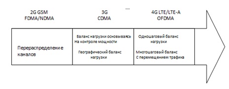
Fig. 1.5 Typical load balancing schemes in mobile networks of different generations
1.1.3 Load balance in 2G GSM networks
Figure 1.6 shows two multiple access technologies used in global mobile communication networks (GSM). In Frequency Division Multiple Access (FDMA) mode, signals for different users are transmitted in different frequency ranges simultaneously. In the Time Division Multiple Access Mode (TDMA), signals for different users are transmitted in the same frequency band at different times [19].
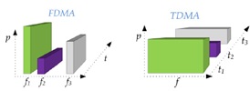
Figure 1.6.Multiple access with frequency (FDMA) and time (TDMA) channel allocation [19]
GSM networks simultaneously use FDMA and TDMA. In FDMA, the operator distributes the entire spectrum to several carrier frequencies, and each carrier has a unique frequency. In TDMA, each carrier is divided into eight time slots. Therefore, users transmit their signals at different time intervals of different carriers.
If neighboring cells assign their users the same time interval on the same carriers, then these users experience significant multi-channel interference interference. In order to solve this problem, GSM network operators use frequency reuse technology to separate carrier channels in neighboring cells. Figure 1.7 shows a typical 7-element frequency reuse technology (FRF = 7). The mobile network consists of three clusters, each cluster has 7 cells. All carriers are divided into 7 groups, group A, B, C, D, E, F, G, respectively. In the cluster, each cell is pre-allocated one corresponding group of non-volatile frequencies. In order to reduce channel-wide impacts, a frequency group can be reused in the cells of neighboring clusters if the distance exceeds the minimum frequency reuse distance.
Channel borrowing is a popular load balancing method in GSM networks [20]. The basic idea is that a hot cell "borrows" carriers from intracluster neighboring cells. For example, in Figure 1.7, it is assumed that Cell1 is an overloaded cell and uses all carriers in Group A, whereas Cell6 and Cell7 are slightly loaded. Then Cell1 borrows some of the free frequencies from neighboring intracluster cells, including free frequencies in group F from Cell6, and free carriers in group G from Cell7.
There are three typical channel redistribution schemes for GSM
Simple borrowing scheme (SB-Simple borrowing scheme): the hot cell uses a free carrier from neighboring intracluster cells, and a channel blocking mechanism is used [39].
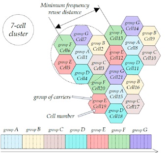
Fig. 1.7 Frequency reuse in GSM
The channel blocking mechanism is aimed at reducing channel-wide interference resulting from the "borrowing" of channel frequencies. So, when a hot cell occupies a carrier, the cells of neighboring clusters within the minimum frequency reuse distance cannot use this carrier [35]. For example, in Figure 1.7, if Cell1 "borrows" a frequency (in Group F) from Cell6, Cell13 and Cell20 from neighboring clusters cannot use this carrier (in Group F). This is because the distance from Cell1-to-Cell13 and Cell1-to-Cell20 is less than the minimum frequency reuse distance.
- The hybrid assignment scheme (HA - Hybrid assignment scheme) is also based on the redistribution of channels [27][39]. In HA, each cell divides its frequencies into two sets: it leaves one set only for its own use; and the other set, in combination with the channel blocking mechanism, can be used by neighboring cells [39].
- Channel allocation without locking scheme (CBWL – Channel borrowing without locking scheme). In cbwl, an overloaded cell uses "borrowed" frequencies to provide services to users in the inner zone of the cell, crystallizing a reduced signal power level. Thus, the community interference interference caused by "borrowed" frequencies is slightly greater than for SB/HA. However, the channel blocking mechanism in CBWL is not necessary, and the same frequencies can be used by cells in neighboring clusters [25]. CBWL can achieve more efficient spectrum utilization compared to SB and HA.
1.1.4 Load balance in CDMA 3G networks
Multiple access. 3G standards (UMTS, CDMA2000) use broadband multiple access technology with code division of channels (CDMA), as shown in Figure 1.8. In the cell, users simultaneously transmit signals in the same frequency band. Therefore, the user's signal acts as a hindrance in the communication channel for other users. Load balancing can improve the performance of CDMA networks by reducing the number of users in an overloaded cell, thereby reducing internal network interference.
In 3G CDMA networks, all cells use the same spectrum, which leaves little room for channel redistribution. Accordingly, load balancing has a different approach: a loaded cell transfers part of the load to less loaded neighboring cells [30, 35, 37, 49]. Consider two main types of load balancing in CDMA networks, including a power-based load balancing scheme and a geographical load balancing scheme.
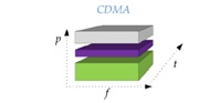
Figure 1.8-CDMA multiple access
Load balance based on power control. Figure 1.9 illustrates the basic idea of a power-based load balancing scheme in WCDMA networks.
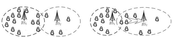
Figure 1.9Load balance based on power control
Loaded BS1 reduces the transmission power in the channel or rejects user requests to increase the transmission power [WZ05]. As a result, some users will be moved to a less busy BS2. The reduced number of users in Cell1 will lead to an improved signal-to-noise ratio for Cell1.
Geographical Load Balancing was investigated in [30] [37]. A prerequisite of GLB is that each BS is equipped with smart antennas. Smart antennas use smart signal processing algorithms to determine the direction of the signal destination, and then dynamically track the target user by forming an antenna pattern [37].
The radio network controller (RNC – radio network controller) collects information about the location of users to find out about the time-varying load distribution in mobile networks. Then, RNC uses complex calculations, such as a genetic algorithm, to optimize the coverage of each cell and adjusts the pattern of smart antennas. Thus, GLB intelligently changes the mobile coverage according to the geographical distribution of the load.
Compared to the load balancing scheme based on power control, GLB can more precisely adjust the cell coverage. This is because complex calculations allow you to precisely adjust the antenna pattern, thereby ensuring a good load distribution between the cells. The limitation of GLB is that BS must be equipped with smart antennas, which are more expensive than conventional sector antennas.
1.1.5 Balance features in LTE networks
Compared to 3G networks, the 4G network (3GPP LTE/LTE-Advanced Network), provides higher data transfer rate requirements for services. Due to the high efficiency of spectrum use for multiplexing with Orthogonal Frequency Division Multiplexing (OFDM - Orthogonal Frequency Division Multiplexing), LTE/LTE-Advanced networks use multiple access with Orthogonal Frequency Division Multiple Access (OFDMA - Orthogonal Frequency Division Multiple Access) as a multiple access technology.
The main idea of the OFDM system is the use of narrow mutually orthogonal subcarriers for data transmission. As shown in Figure 1.10 (Figure 4.4 in [22]), OFDM distributes a high-speed data stream into several parallel low-speed data streams. Each low-speed data stream is transmitted to separate subcarriers. At the time of selection of a single sub-carrier, the other sub-carriers have zero value. Therefore, the subcarriers are orthogonal.
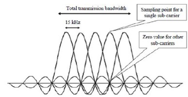
Fig. 1.10–OFDM subcarriers [22]
OFDMA is achieved by assigning different subcarriers to different users. OFDM/ OFDMA provides the following advantages for mobile communication networks:
- High spectral efficiency: the cell allocates different elevators for different users. Due to the orthogonality of the subcarriers, intra-zone obstacles are significantly weakened. Therefore, the OFDMA system can achieve high speed [36].
- Frequency selective attenuation: The OFDMA system can effectively combat frequency selective attenuation. This is due to the fact that OFDM converts broadband transmission to narrowband transmission on several subcarriers, and each subcarrier can be used as a flat attenuation channel [22].
- Flexible resource allocation: in accordance with the channel conditions, the OFDMA system can select certain uplifters for transmission, thereby ensuring flexible resource allocation; the OFDMA system can also make full use of the variety of frequencies and users to achieve high system performance [22, 36].
To achieve high cell capacity, one of the technologies of frequency reuse in LTE /LTE-Advanced networks is that all cells have the same spectrum (FRF = 1) [17, 31]. Load balancing schemes based on channel borrowing, which are widely used in 2G GSM networks, are not widely used in these networks.
In LTE/LTE-Advanced mobile networks, which are based on OFDMA, intra-zone interference is negligible due to the orthogonality of subcarriers.[86] In addition, LTE/LTE-Advanced are distributed control networks. It is worth noting that when using distributed control networks with load balance circuits that regulate power, problems with coverage and signaling may arise. Therefore, load balancing schemes based on power management methods that are used in 3G CDMA networks have not been widely used in LTE / LTE-Advanced technology networks based on OFDMA.
For effective load balancing in LTE / LTEAdvanced 3GPP release-8 networks, the load balance of moving users (MLB) is determined as functions of SON1 (self-organized networks) [15]. MLB aims to move the traffic load from a cell of the "hot spot" type (which is the busiest) to less loaded neighboring cells, correcting the transmission channel offset (HOoff) to ensure continuous data transmission.
As a rule, MLB consists of two stages: selecting a donor cell for network resources and redirecting traffic [40-42, 44-48, 68, 80, 83, 95]. At the stage of selecting the donor cell of network resources, the most loaded cell selects the less loaded neighboring cells as partners, which are also called "target cells" or, in some MLB schemes, "selected neighboring cells". This stage in many conventional MLB schemes is based on loading an adjacent cell with excess traffic.
At the stage of balancing the load of moving mobile network users, the cell with the highest load calculates the traffic volumes that require movement and adjusts the HOoff to each cell of the partner. The configured HOoff increases the radio coverage area, thereby moving users on the border of the cell service area to the selected partner cells [43]. The traffic redirection stage is illustrated in Figure 1.11, where Cell1 is the cell that intends to take traffic from the partner Cell2 for service. However, the RSRP2 of the user from BS2 is weaker than the RSRP1 from BS1, and therefore the user at the boundary of the cell service area cannot receive redirection. In order to move the boundary of the cell maintenance zone, BS1 configures its HOoff by BS2.
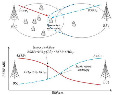
Figure 1.11–Illustration of the MLB traffic redirection stage
After the solid transition condition (event A3 in [18]), as shown by expression (1.2), is met, the user will be passed to BS2.
where HOhys is the handover hysteresis, HOhys=2dB.
HOhys can provide a hysteresis value of Hoof(1,2)+RSRP2, which is 2dB more than RSRP1. This is necessary to combat the "ping pong handover". Ping-pong handover means that the user is very quickly assigned to Cell 2 and then turned back to Cell 1 [23] and so on.
1.2. Conclusions to section 1
An analytical review of scientific papers on the subject of dissertation research was carried out to establish the conditions and requirements for the provision of communication services in wireless access networks. It is established that mobility management and subscriber load balancing mechanisms have a decisive influence on the processes of providing communication services and ensuring their continuity.
Most methods of subscriber load balancing can be divided into two main types: load balancing based on the probability of blocking requests and balancing based on the load indicator. The first type is characterized by a smaller amount of service data, since the balancing process begins only when the threshold value of the probability of blocking requests is exceeded. For example, load distribution between cells is performed by reducing the radius of the overloaded and increasing the radius of neighboring cells by adjusting the radiation power of base stations.
The second type of load balancing is preferable from a practical point of view, since it takes into account the throughput and the degree of load balancing both in the selection of the cell and in the process of executing the handover.
For example, the load balancing process starts from the busiest cell in order to achieve uniform load in the network.
However, all the mechanisms considered in the load balancing process use the resources of only neighboring cells. Therefore, such mechanisms are not suitable for situations where groups from neighboring cells are located under peak loads. Hence follows the formulation of the scientific task of the work.
List of sources
- Yevgeni Kouch eryavy, Giovanni Giambene, Dirk Staehle, Francisco Barcelo- Arroyo, Torsten Braun, and Vasilios Siris, ôTraffic and QoS management tin wireless multimedia networks: COST 290 Final Report,ö Springer, 2009.
- ð. ▓. ┴ÓÛ, ▓. ┴. ÎÓÚÛ¯Ô±³ÛÞÚ, ▀. ┬. ÏÞÚÛÓ ‗Ó ╠. ╠. ├ÝÓ‗¸¾Û, ôд¯±│ß ´│õÔÞ¨ÕÝÝ õ¯±‗¾´Ý¯±‗│ Óõ│¯Õ±¾±¾ ±Þ±‗Õý ý¯ß│ٳݯү þÔ' þÛ¾ Ô ´ÕÕÔÓÝ‗ÓµÕݯý¾ ÕµÞý│ ¯ß¯‗Þ,ö ¾ Ãß│ÝÞÛ¾ ‗Õþ õ¯´¯Ô│õÕÚ ┬±Õ¾ÛÓ┐ݱ³Û¯┐ ÝÓ¾Û¯Ô¯-´ÓÛ‗޸ݯ┐ ۯݶÕÕÝ÷│┐ ôо¸Ó±Ý│ ´¯ßÙÕýÞ ‗ÕÙÕÛ¯ý¾Ý│ÛÓ÷│Ú ‗Ó ´│õÒ¯‗¯ÔÛÓ ¶Ó§│Ô÷│Ô Ô ÒÓÙ¾þ│ ‗ÕÙÕÛ¯ý¾Ý│ÛÓ÷│Ú û 2012,ö 2012, pp. 89û91.
- INFSO-ICT216284 FP7 SOCR ATES, ôFinal report on self-organization and its implications in wireless access networks,ö D5.9, v1.0, Dec ember 2010
- Ozan K. Tonguz and Evsen Yanmaz, ôOn the theory of dynamic load balancing,ö IEEE Global Communications Conference (GLOBECOM), vol.7, pp.3626û3630, December 2003.
- Ming Zhang and Tak-Shing P. Yum, ôComparisons of channel- assignment strategies in cellular mobile telephone systems,ö IEEE Transactions on Vehicular Technology, vol.38, no.4, pp.211-215, November 1989.
- Ridha Nasri and Zwi Altman, ôHandover adaptation for dynamic load balancing in 3GPP long term evolution systems,ö International Conference on Advances in Mobile Computing and Mul timedia (Mo MM), pp.145-154, Dec ember 2007.
- Raymond Kwan, Rob Arnott, R. Paterson, Riccardo Trivisonno, and Mitsuhiro Kubota, ôOn mobility load balancing for LTE systems,ö IEEE Vehicular Technology Conference-Fall (VTC-Fall), pp.1-5, September 2010.
- Ying Yang, Pengfei Li, Xiaohui Chen, and Weidong Wang, ôA Highefficient algorithm of mobile load balancing in LTE system,ö IEEE Vehicular Technology Conference-Fall (VTC-Fall), pp.1-5, September 2012.
- Mahmudur Rah man and Halim Yanikomeroglu, ôEnhancing cell-edge performance a downlink dynamic interference avoidance scheme with inter-cell coordination,ö IEEE Transactions on Wireless Communications, vol.9, no.4, pp.1414-1425, April 2010.
- Mamoru Sawahashi, Yoshihisa Kishiyama, Akihito Mori moto, Datsuke Nishikawa, Motohiro Tanno, ôCoordinated multipoint transmission/reception techniques for LTE -Advanced,ö IEEE Wireless Communications, vol.17, no. 3, pp.26û34 June 2010.
- Minghai Feng, Xiaoming She, Lan Chen, and Yoshihisa Kishiyama, ôEnhanced dynamic cell selection with muting scheme for DL CoMP in LTE-A,ö IEEE Vehicular Technology Conference-Spring (VTC-Spring), pp.1-5, May 2010.
- Tomson Joe Kahwa and Nicolaos D. Georganas, ôA hybrid channel assignment scheme in large-scale, cellular-structured mobile communication systems,ö IEEE Transactions on Communications, vol.26, no.4, pp.432-438, April 1978.
- Hua Jiang and Stephen S. Rappaport, ôCBWL: a new channel assignment and sharing method for cellular communication systems,ö IEEE Transactions on Vehicular Technology, vol.43, no.2, pp.313-322, May 1994.
