Abstract
List of contents
- Introduction
- 1. The main theoretical provisions
- 2. Description of the algorithm of the area method
- 3. Study of synchronous dynamic stability by the area method
- 3.1 Preparation of initial data
- 3.2 Experience 1
- 3.3 Experience 2
- 3.4 Experience 3
- 3.5 Experience 4
- 3.6 Analysis of the results of the experiments
- Conclusion
- References
Introduction
Dynamic stability is the property of a system to maintain the initial or close to the initial mode under finite perturbations [1].
Dynamic stability is a relative requirement and it must be provided under certain conditions.
Dynamic stability analysis is the analysis of finite perturbation modes.
Ensuring the dynamic stability of the power supply system (SES) allows significantly increase reliability. Disturbances often occur in power supply systems (ES), this is due to the disconnection of powerful loads, generators and transformers of motors, power lines (power lines).
When a disturbance occurs, transients occur. These transients can be at large perturbations and small speed changes. With large perturbations , they consist in the following: checking the dynamic stability of the system under given perturbations; calculation of parameters mode during transients in order to assess the acceptability; evaluation of the effectiveness of various sections for improving sustainability.
Processes with large perturbations and large changes in the angular velocity of the rotor, generators are often called asynchronous modes, which include asynchronous running, and resynchronization, resulting stability.
The correctness of the calculations of the transition process largely depends on the point from which they are described the main elements of the power supply system (SES) are primarily generators and their systems load regulation. The simplest way is to study the dynamic stability of the system power supply (SES) is the use of the area method, which makes it possible to obtain qualitative and approximate quantitative assessment of dynamic stability conditions.
Acceptable criteria and requirements for dynamic stability are established according to GOST R 58058-2018 [2].
In this paper, dynamic stability under large perturbations is considered.
1. THE MAIN THEORETICAL PROVISIONS
Dynamic stability is the ability of a system to restore after a large disturbance, the initial state or a state almost close to the initial one (permissible under the operating conditions of the system) [1].
Dynamic stability should be judged by the nature of the change mode parameters for final results. The regime change is characterized by nonlinear equations reflecting the effect of the corresponding disturbing factor.
In dynamic stability, specific knowledge is important initial conditions (time, place, type, duration).
The concept of stability of a dynamic system schematically illustrated by the example shown in Figure 1.1 [1].
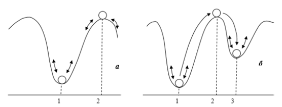
1.1., and position 1 is the position of stable equilibrium, since when the ball deviates from this equilibrium position (as a result of perturbation) it returns to the stable equilibrium position 1. Position 2 is the position unstable equilibrium, because even with a slight (small) deviation of the ball (perturbation), it leaves this equilibrium position.
In the case of small disturbances (small deviations of the ball from the position equilibrium) speak of stability in the "small"; in the EES, this corresponds to the concept of static stability. In the case of significant large disturbances (large deviations of the ball from the equilibrium position) speak of stability "in the big one"; in the EES, this corresponds to the concept of dynamic stability.
If the disturbance is so large that the dynamic stability of the system (the ball in Fig. 1.1, b as a result of such a large the perturbation deviates from the equilibrium position 1, "skips" the position unstable equilibrium 2 and turns out to be stable after some fluctuations 3) and the system turns out to be in a different equilibrium position, they talk about the resulting stability.
2. DESCRIPTION OF THE ALGORITHM OF THE AREA METHOD
The general idea of the area method is to compare the acquired a kinetic energy system at a certain interval of existence an emergency situation with a reserve of work that can be performed during braking objects of the system after the elimination of the accident. If the acquired kinetic energy exactly equal to the remaining margin for braking operation, then the time interval the existence of an accident is assumed to be limiting in terms of dynamic stability [4].
Let's consider the main processes, as well as the equations for a large perturbation in the simplest EES [3].
Let the power line in Figure 2.1 include two parallel circuits, and one circuit is shut down for some reason. Total resistance links x=x’d+x*l will increase thus , the maximum angular power characteristic in the post - accident mode will be lower, than in pre-emergency. The pre-emergency (I) and post-emergency (II) angular power characteristics are shown in Fig. 2.2, a.

where P is the electromagnetic power output by the generator, TJ is the inertia constant of the generator rotor.
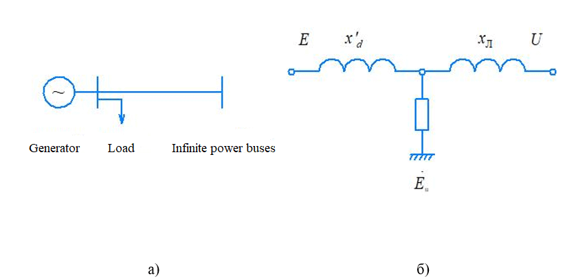
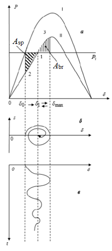
As a result of a sudden disconnection of one chain of a two-chain line due to the inertia of the rotor at the first moment of time after the disturbance we get from point 0 of the angular power characteristic to point 2. In this position, the turbine power is greater than the electromagnetic output of the generator power, i.e. acceleration has a plus sign and acts to increase the angle of the generator, as a result, the angle of the rotor increases from the value δ0 to the value δ1.
As a result of this movement from point 2 to point 1, the rotor gains acceleration energy due to the inertia of the rotor mass, determined by the integral

The acceleration energy is equal to the shaded area on the left in Figure 3.1, a; it is called the acceleration site.
Due to inertia, the rotor "skips" the equilibrium position 1 and moves in the direction of increasing the rotor angle from the value δ1 to the value δmax. In this range of angles , the electromagnetic the power of the generator is greater than the power of the turbine, the power imbalance is negative and, consequently, the acceleration of the rotor is negative, as a result of which the movement of the rotor is slowed down and gains braking energy.

The braking energy of the rotor is equal to the right shaded area in Fig. 3.1, a; it is called the braking area.
If there is no energy loss, then

Since energy losses actually exist due to friction, ohmic losses and energy dissipation in the damper circuits, the rotor oscillations gradually fade, as shown in Fig. 2.1, b, as well as the trajectory of the rotor angle in time (Fig. 2.1, c). In this case, the dynamic stability of the simplest EPS is preserved.
Let's consider a typical case (Fig. 2.3).
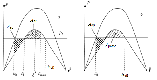
2.3, and it is characteristic that the rotor, compensating for the acceleration energy braking energy, "came" to the angle value δmax>δ*, where - the value of the angle corresponding to the maximum of the angular power characteristic. From this it follows that the rotor can gain braking energy up to the angle value δbefore , up to where the electromagnetic power of the generator remains higher than the turbine power. This the potentially possible braking energy is called the energy of possible braking (Fig. 2.3, b), which in the figure corresponds to the site of possible braking
Obviously, in order for dynamic stability not to be violated, it is necessary that the condition is met

which was called the area criterion, and the method itself based on the verification of the criterion is called the area method.
3. INVESTIGATION OF SYNCHRONOUS DYNAMIC STABILITY BY THE AREA METHOD
3.1 Preparation of initial data
Let's consider the method of analysis of synchronous dynamic stability on the example of the simplest electrical system in which the following elements are present: generators, transformers, power lines, system and load (Fig. 3.1).
To conduct the research, the software Mathcad was used, which makes it possible to solve differential equations in the simplest way and visually perform the construction of graphical dependencies of angular power characteristics. By simulation of transients in time has been applied the built-in "Animation" function makes it possible to observe the nature of the transition process.
In the study of the various modes of operation of the EPS, the following were used data about its elements: parameters of generators, transformers and power lines. Specified The initial data are given in Table 3.1. To perform the experiments, these data were entered into the calculation file in the Mathcad environment, as shown in Figure 3.2.
Table 3.1 – Initial data
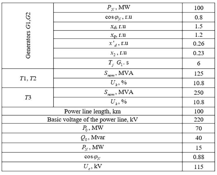

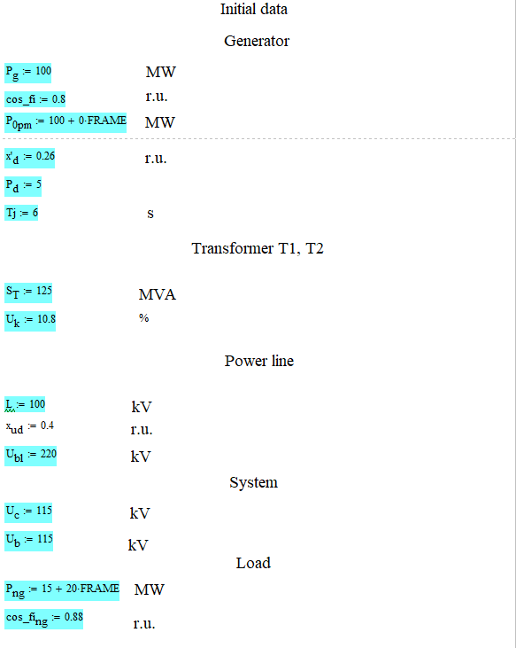
The purpose of this study is to master the methodology of analysis synchronous dynamic stability of the simplest electrical system based on the integration of the differential equation of rotor motion, investigation of the effect of damping and constant inertia of the rotor on the character the transition process. The following issues were considered during the study:
1. Determination of the maximum power value and the corresponding angle values at which synchronous dynamic stability is maintained in case of disturbance caused by disconnection of one circuit of a two-chain power line;
2. Analysis of the effect of the damping coefficient Pd and the constant inertia of the rotor Tj of the generator for the specified in paragraph 1, the parameters and nature of the transition process;
3. Analysis of the influence of the load that is connected to the generator buses on the parameters specified in paragraph 1.
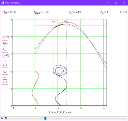
To analyze the flow of the above processes , the following was carried out modeling of various modes of operation of the EES. As a result , the following were obtained graphical dependencies describing the nature of the transients. Detailed results are presented in paragraphs 3.2-3.5.
3.2 Experience 1
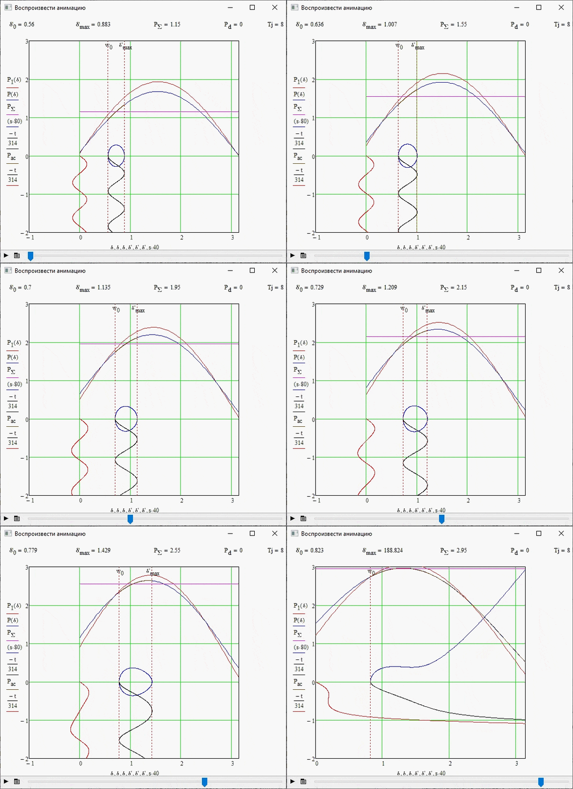
This experiment was carried out without changing the initial data of the system, as well as if there is no damping effect, i.e. Pd=0. Figure 3.3 shows the stability boundary for this case, as well as the parameters of the required quantities.
3.3 Experience 2
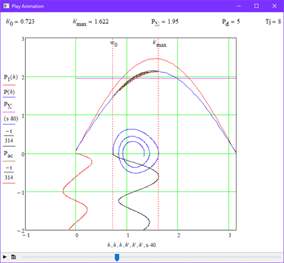
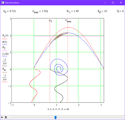
In this experiment, the influence of damping power was investigated. windings on the stability of the system. Figure 3.3 shows the stability boundary at Pd=5. For clarity, we repeat the experiment, but at the same time we increase the value of the damping coefficient by 2 times, i.e. Pd=10 (Fig 3.4).
3.4 Experience 3
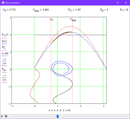
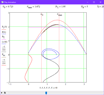
In this experiment, the influence of mechanical constant inertia was considered the generator indicates the nature of the transition process. To do this , various tasks were set parameter values Tj with the damping value unchanged Pd=5. Figure 3.6 shows the stability boundary at Tj=16, and Figure 3.7 shows it at Tj=20.
3.5 Experience 4
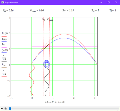
In this experiment, the influence of the load connected to the generator buses on the transient process was considered. Various values have been set for this the load capacity on the system tires Png. The resulting graphs are shown in Figures 3.8 and 3.9.
3.6 Analysis of research results
After analyzing the obtained graphs, the following main points can be identified:
1. For an unregulated system, stability is broken at angles greater than 90°.
2. The addition of a damping winding makes it possible to accelerate the attenuation of the oscillatory process in the rotor.
3. Increasing the stability limits of Tj also does not affect, but, like Pd, it reduces the number of vibrations in the rotor.
4. Increasing the power of the load connected to the generator allows you to significantly expand the boundaries of the stability of the system.
Conclusion
In this paper, the main theoretical provisions of the dynamic stability of the electric power system were considered.
The key theoretical points on the algorithm of the area method for conducting subsequent experiments are highlighted.
Simulation of transient processes in time was performed using the program Mathcad.
The tasks have been completed in full.
References
- Эрнет А.Д., Электромеханические переходные процессы в электрических системах: Курс лекций. – Нижневартовск: Изд-во НВГУ, 2013 – 130 с.
- ГОСТ Р 58058-2018 «Устойчивость энергосистем. Нормы и требования» - Введ. 01.01.2019 г.
- Воропай Н.И., Электромеханические переходные процессы в электроэнергетических системах: учеб. пособие / Н.И. Воропай. – Благовещенск: Изд-во АмГУ, 2013. – 151 с.
- Оценка динамической устойчивости энергосистем на основе метода площадей: научная статья/ Лизалек Н.Н., Ладнова А.Н., Тонышев В.Ф., Попова Е.Ю., Вторушин А.С. – Новосибирск – СибНИИЭ ИАЭС, НГАВТ, 2013. – 14 с. – Текст: электронный // Электронно-библиотечная система eLIBRARY : [сайт]. – URL: https://elibrary.ru/item.asp?id=18879238 (дата обращения 17.07.2022). – Режим доступа: для авториз. пользователей.
