Abstract on the topic of graduation work
- Introduction
- 1. General information about quadcopters
- 2. Development of control equipment
- 2.1 Development of a control panel
- 2.2 Receiver development
- 3. Selecting components for quadcopter assembly
- Conclusions
- Source List
Introduction
Unmanned Aerial Vehicles (UAVs) are now appearing in many areas of human life - from their use for entertainment purposes as toys, amateur photography and videography, quadcopter racing with a first-person view, to visual monitoring of the state of various networks and communications, treatment of farmland with chemicals, cargo delivery, and military applications. The vast majority of these drones are multicopters. A multicopter is a helicopter-type aircraft with three or more propellers. Such devices are often referred to as drones (drone). This word was first used to describe an unmanned aerial vehicle in the mid-thirties of the last century. It denoted a target biplane, whose wings were fastened together with steel wire to give rigidity and emitted a sound similar to a bee buzzing. Nowadays, a drone is not only referred to as an unmanned flying drone, but also as a land vehicle, underwater vehicle, and zoomorphic and anthropomorphic robots. From the point of view of terminology, this is not correct, since not all of the listed devices perform the specified work autonomously, without the participation of an operator. Therefore, to avoid inaccuracy, flying machines built on a helicopter scheme with several carrying propellers should be called multicopters or multirotors. It can be called a drone, for example, if the multicopter is flying along a predetermined route or heading to the starting point when the signal with the control equipment is lost.
The control chip or flight controller (PC), an electronic device with a microcontroller with installed software, sensors for orientation in space, and connectors for other components, plays an important role in quadcopters that determines its functionality. The PC receives and processes commands from the user, tracks motion, calculates proportional-integral-differential coefficients (PID) in accordance with the software and sends control signals to actuators. And structurally identical flight controllers can run different software to improve flight performance depending on the quadcopter's configuration.
1. General information about quadcopters
Whether the quadcopter is assembled from a kit or ready to fly after purchase, it consists of the following basic parts:
– Battery - Lithium polymer (LiPo), less commonly lithium-ion (Li-Ion).
– Power Distribution Board. Has a connection node for the battery and multiple outputs to power all quadcopter components. Can have voltage converters with 5V, 12V outputs to power servos, cameras and other equipment.
– The flight controller that controls the quadcopter. In addition to the microcontroller, includes an inertial measurement unit - accelerometer, which measures linear acceleration on 1-3 axes and gyroscope, which measures the angle of inclination on the main axes. Additionally, the PC board can have a magnetometer for determining the parts of light and a barometer, which provides stable hovering at an altitude selected by the operator. In addition, a GPS module can be connected to realize automatic flight to specified points, circling around points of interest and returning to the starting point.
– Four electronic speed controllers (ESC - Electronic Speed Controller), which regulate the speed of the engines based on the signals given to them by the flight controller.
– Four asynchronous collectorless motors with propellers that generate lift. The latter have a different shape for counterclockwise and clockwise direction of rotation. The propellers can have two to four blades, either folding, which are locked into shape by centrifugal force, or solid.
– Remote control system, including a remote control, from which the control signals are sent and the receiver installed on the quadcopter, transmitting signals to the PC. Communication between the two is accomplished via radio waves at frequencies typically 2.4GHz or 5.8GHz.
– The frame on which all the components are mounted. In the most common configuration, it is symmetrical about the longitudinal and transverse axis. It is most often made of plastic, carbon fiber, or fiberglass, and less often aluminum.
The following additional equipment can also be installed on the quadcopter: servos, low-battery sound emitter, GPS module, camera pendant, FPV (First Person View) system. The latter is a camera mounted on the quadcopter with a video transmitter that sends data to a video receiver, from which the image is displayed on the screen or special glasses. It may include an OSD (On Screen Display) board that displays flight data on the screen, such as altitude, distance from the launch point, coordinates, and battery voltage.
Since each component currently has a huge number of analogs, more details about them will be written in the following subsections. As for the controls, it's worth noting that to counteract the gyroscopic effect, one pair of diagonally opposed screws rotate clockwise, the other counterclockwise. They are labeled CW (Clockwise) and CWW (Counterclockwise).
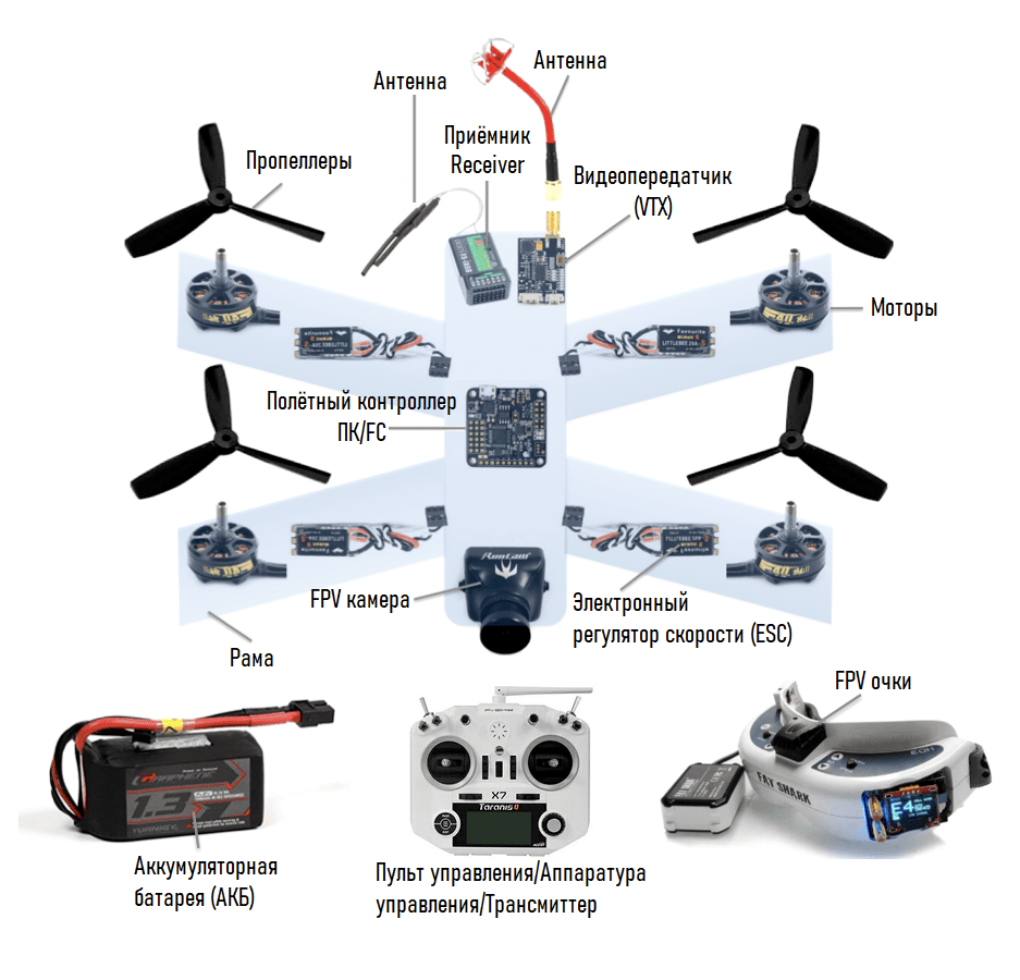
Figure 1 – Structural diagram of the quadrocopter structure
Signals are sent to the receiver from the control equipment by means of a radio signal of a certain frequency on separate channels - there is a separate channel for each action that sets the position of the quadrocopter in space. The receiver receives signals from the equipment and transmits them to the flight controller, which processes the incoming signals and, in accordance with the software and sensor data, creates a control signal via pulse-width modulation for electronic speed controllers, which directly control the electric motors with propellers, creating lift.
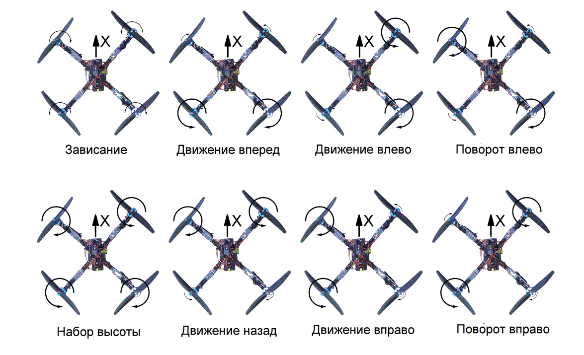
Figure 2 – Quadcopter motion control
2.Development of control equipment
2.1 Development of a control panel
An important parameter of the control hardware is the data transmission protocol. Not all flight controllers currently available support the PWM protocol, which transmits separate signals on separate channels. Therefore, it is initially worth developing equipment that works according to the PPM protocol, which is an analog signal in which several control channels are encoded. On the plus side, it is transmitted over a single signal wire, which makes connection easier, increases reliability and slightly reduces weight. The PPM consists of a sequence of pulses of equal length, the time between pulses tn determines the state of channel n.
The maximum value of a channel will correspond to a pulse that is 2ms long, the minimum value will correspond to a pulse that is 1ms long. In the graph below, the first channel is at its maximum value, the second channel is at its minimum value, and the third channel transmits the average value. In 8-channel control equipment, the series time, i.e. pulses of all channels, is 22.5ms. A total of 9 pulses are sent, with the initial pulse indicating the start of the series transmission.

Figure 3 – Data transmission with different channel states
The following parts will be used to build a control panel that transmits signals:
– Arduino Mini board for processing signals from joysticks and switches, transmitting signals to the radio module.
– Radio module NRF24L01 in version with amplifier and antenna for signal transmission to the receiver.
– AMS1117 linear voltage regulator for powering the radio module.
– 2 three-position toggle switches, 2 two-position toggle switches for functions such as switching flight modes, putting the quadcopter in on/off state.
– 2 joysticks to control throttle level, pitch, roll, yaw.
Trimmers can be used to set the zero value of the joystick axes because the joysticks can produce values other than zero in the center position. In this paper, joystick trimming will be implemented by software.
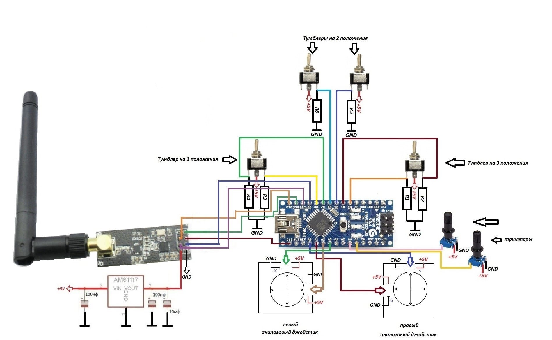
Figure 4 – Wiring diagram for control panel parts
Additional channels are directly transmitted to the receiver, their functionality is configured in the firmware program for the flight controller. After flashing, e.g. in BetaFlight program, it is necessary in the "Configuration" tab under "Reciver" and set the item "PPM RX input" for the flight controller to receive this signal.
2.2 Receiver development
To build the receiver you will need an Arduino Mini to process the signals from the radio module and transmit the signals to the flight controller, an NRF24L01 radio module and an AMS1117 linear voltage regulator to power the radio module. It is possible to use the NRF24L01 with a signal amplifier and antenna for maximum transmission range, and achieve weight reduction of such a board by removing the plastic antenna sheath and attaching it directly by soldering. This will reduce the weight by 12 g with the total weight of the radio module being about 15 g. This will achieve almost identical weight to the board without amplifier and antenna, while increasing the communication range by up to two times.
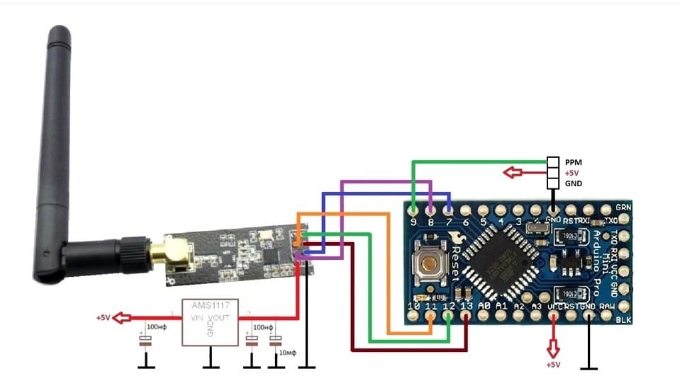
Figure 5 – Receiver parts wiring diagram
3.Selecting components for quadcopter assembly
For the selection of parts, first of all, it is necessary to determine the scope of application of the quadcopter. In this work will be considered components that will allow you to build a quadrocopter with a developed automation system and the ability to carry out long flights (30-40 minutes), but also has excellent dynamic characteristics. To do this, let's determine the choice of a suitable frame, which will allow you to install the rest of the parts. A 280-300 mm frame with several mounting pads mounted on top of each other, such as the XL7, will do. This type of frame is lightweight because it is made of carbon fiber, is available from many manufacturers and is widely distributed, so it is possible to buy spare frame beams in case the main ones break.
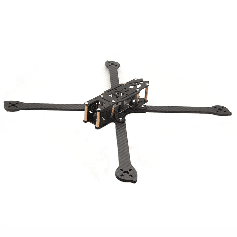
Figure 6 – XL7 frame
The size of the internal pad will allow you to install all the necessary equipment, including FPV camera, under the pad can accommodate a high capacity battery, on the upper pad will be mounted GPS module. This frame configuration is manufactured in several sizes, the number in the frame name indicates the recommended size of the supporting screws, in this case it is 7 inches. The advantage of this propeller size is the wide selection of propellers available. A good option would be the HQProp DP7X4X3 three-blade propellers, which are a proven brand due to their quality construction and low price.
The EMAX ECO II 2207 1700KV is one of the best value for money and energy efficient motors for these propellers. The 1700KV model will give good dynamic performance. It is possible to increase the flight time by using motors with lower KV. The quality class of these motors guarantees good build quality and low vibration, which will have a positive effect on the gyroscope and other sensors. With the selected propellers, this motor will draw 27A at 100% throttle from a 4S battery. The thrust of one motor is 980g and the approximate weight of the quadcopter will be 1000g. The total thrust to weight ratio will be 3.9, which is excellent and will allow for future payload weight increases.
With the current consumption of the motors in mind, let's choose suitable speed controllers with a power rating of 25-30A. Let's opt for four separate ESCs in order to minimize the cost of repair, as the 4-in-1 speed controller board is often damaged when the quadcopter is dropped. If a separate controller fails, it will be easier and cheaper to replace it. ESC c 32-bit controller STM32F0 should be considered only medium and high price range because of the presence of interference on the signal wires ESC in the lower price range. In this case, the latest generation of speed controllers provides an insignificant reduction in data transmission delay, which will not be felt when controlling the quadrocopter. Therefore, ESCs with support for digital Dshot protocols will be prioritized. An excellent option are Hglrc 30A. These regulators support the Dshot600 data transfer protocol, which will provide a sufficiently low latency. They differ from similar ESCs by their low price while meeting the stated characteristics. Designed for 3-5S battery, this voltage is suitable for powering the selected motors. It should be noted that the selected ESCs do not have BEC, so you should take this into account when choosing a flight controller, it should have a power distribution board with 5V and 12V stabilizers or a separate power distribution board will be required.

Figure 7 – ESC connection diagram to the flight controller
For a flight time of 30-40 minutes, you'll need a 5200mAh Li-Po battery with four cells to deliver the 14.8V design voltage for the motors. It is also possible to assemble a battery from four 18650 Li-Ion cells. This will increase the flight time to ten minutes.
The most suitable PC for automatic control will be STM32F4 and STM32F7 based devices. The last generation has better characteristics, but STM32F4 has enough flash memory and clock frequency to solve all necessary tasks. The Matek F405-SE flight controller will be suitable for the thesis work. This is an updated version of Matek F405-STR, which has a modern barometer with increased sensitivity DPS310, 6 UART ports (one of which is inverted for operation via SBUS protocol), 2 I2C ports. The combined gyroscope and accelerometer module is a reliable MPU6000, giving readings with minimal interference. The PC has a built-in power distribution board with stabilized 5V and 12V power outputs, built-in OSD board. The Matek F405-SE is great for autoflight, the INAV firmware will be the best software.
The Matek M8Q-5883 will be used as the GPS module. It has the best quality and reliability, light weight, equipped with genuine u-blox SAM M8Q chip. It has a low noise 3.3V stabilizer and RF filter, and has a built-in QMC5883L magnetometer. Can use GLONASS and GPS systems simultaneously for more accurate positioning. A GPS module holder is required for installation and can be purchased or made yourself.
The Rx pin of the GPS module is connected to the Tx pin of the flight controller, the Tx pin of the module is connected to the Rx pin of the PC, the magnetometer pins CL and DA are connected to the same name pins on the PC.
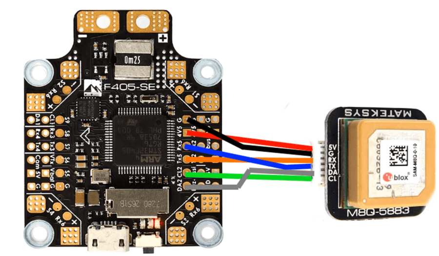
Figure 8 – Connecting the GPS module to the flight controller
As control equipment selected FrSky Taranis QX7 with receiver R-XSR, operating at 2.4 GHz, has 16 channels and works on the protocols SBUS, CPPM. This equipment allows you to control the quadrocopter at a range of 3-5 km, it is possible to install an amplifier for the transmitter, which allows you to achieve a range of signals up to 8 km.
With regard to FPV equipment operating at 5.8GHz, for the diploma work will be used video transmitter AKK FX2 Ultimate Mini with a power of 600 mW, which allows you to transmit video signals to a distance of 7 km. It will require a UFOFPV Pagoda-2 antenna with an SMA connector. The RunCam Phoenix 2 camera, which has an excellent horizontal resolution of 1000TVL, works well in low light conditions. A monitor with a built-in LT58025 5.8GHz video receiver with a 7-inch screen diagonal will be required to receive the video signal. This monitor has a built-in battery, receives up to 40 channels, and is an affordable replacement for FPV goggles.
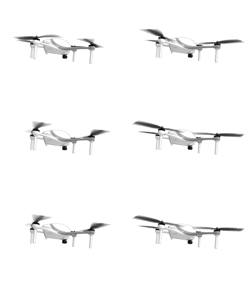
Figure 9 —Motion of quadcopter propellers
(animation: 8 frames, 5 repetition cycles, 44 kilobytes)
Conclusions
In this paper, the main criteria for selecting all parts of the quadrocopter were given, the control equipment for the quadrocopter was developed to allow control of the aircraft at a similar level to commercially manufactured control equipment, and the components were selected to assemble a quadrocopter with an advanced automatic flight system, excellent dynamic performance and flight time.
Source List
1. Мультикоптеры: Новый Вид. [Electronic resource]. - Access mode: www.uav.ru
2. Набиев Р.Н., Газарханов А.Т., Гараев Г.И., Ширинов У.Т., Гамидли Ф.Ф.Методы использования мультикоптера в военных целях// №1, Статьи Националной Авиационной Академии, 2015. Ст. 21-28
3. Контроллеры бесколлекторных двигателей. [Electronic resource]. – Access mode:www.multicopter.ru
4. Ситников Д.В., Бурьян Ю.А., Русских Г.С. Система управления движением мультикоптера.- Омск.:Омский государственный технический университет. Монография, 2012, 5c.
5. Селиванова Л.М., Шевцова Е.В. Инерциальные навигационные системы, Часть1. Одноканальные инерциальные навигационные системы. - М.:2012, 49с.
6. Соловьев В.И., ШабаловП.Г. Инерциальные навигационные системы.-Самара.: 2011,74с.
7. Multicopter Wiki [Electronic resource]. – Access mode:https://multicopterwiki.ru/index.php
