
Abstract
Content
- Introduction
- 1. Power losses in network elements
- 2. Calculation of power losses in power lines
- 3. Calculation of power losses in transformers
- 4. Non-deterministic model of electrical load
- 5. Measures to reduce power losses
- 6. Calculation of energy losses
- 7. The task of calculating modes. Basic assumptions
- 8. Power balance in the power system
- List of sources
Introduction
Electrical power is a physical quantity that characterizes the rate of transmission or conversion of electrical energy. The unit of measurement in the International System of Units (SI) is the watt (Russian designation: Вт
, international: W).
1. Power losses in network elements
To quantify the operation of the elements of the electrical network, its operating modes are considered. The operating mode is a steady–state electrical state, which is characterized by the values of currents, voltages, active, reactive and full power.
The main purpose of calculating modes is to determine these parameters, both to check the validity of modes and to ensure the efficiency of network elements [1].
Determining the values of currents in the network elements and voltages in its nodes begins with building a picture of the distribution of total power across the element, i.e., determining the capacities at the beginning and end of each element. This pattern is called flow distribution.
Calculating the power at the beginning and at the end of the element of the electrical network, take into account the power loss in the resistances of the element and the influence of its conductivities [2].
2. Calculation of power losses in power lines
Active power losses on the transmission line section (Fig. 1) are caused by the active resistance of wires and cables, as well as by the imperfection of their insulation. The power lost in the active resistance of three-phase transmission line and spent on its heating is determined by the formula:
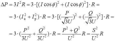
where I, Ia, Ip ‒ total, active and reactive currents;
P, Q, S – active, reactive and total power at the beginning or end of the line;;
U – line voltage at the beginning or end of the overhead transmission line;
R – active resistance of one overhead transmission line phase.

Fig. 1 – To the calculation of power losses on the section of the electric network
Потери активной мощности в проводимостях ЛЕП обусловлены несовершенством изоляции. В воздушных ЛЕП – появлением короны и, в очень незначительной степени, утечкой тока по изоляторам. В кабельных ЛЕП – появлением тока проводимости а его абсорбции. Рассчитываются потери по формуле:
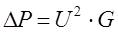
where U – line voltage at the beginning or end of the overhead transmission line;
G – active conductivity of the overhead transmission line.
When designing overhead power lines, power losses on the crown tend to be reduced to zero by choosing such a wire diameter when there is practically no possibility of a crown.
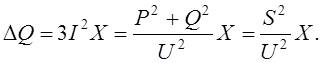
The loss of reactive power in the transmission line section is due to the inductive resistances of wires and cables. The reactive power lost in a three-phase transmission line is calculated similarly to the power lost in active resistors:
The charging power of a power line generated by capacitive conductivity is calculated using the formula [3]:
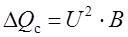
where U – line voltage at the beginning or end of the overhead transmission line;
B – reactive conductivity of the overhead transmission line.
Charging power reduces the reactive load of the network and thereby reduces power loss in it.
3. Calculation of power losses in transformers
Losses of active and reactive power in transformers and autotransformers are divided into losses in steel and losses in copper (load losses). Losses in steel are losses in the conductivity of transformers. They depend on the applied voltage. Load losses are losses in the resistances of transformers. They depend on the load current.
Losses of active power in transformer steel are losses due to magnetization reversal and eddy currents [4]. They are determined by the transformer idling losses ΔРx , which are given in its passport data.
Reactive power losses in steel are determined by the no-load current of the transformer, the percentage value of which is given in its passport data.
Power losses in transformer windings can be determined in two ways:
- according to the parameters of the substitution scheme;
- according to the passport data of the transformer.
Power losses according to the parameters of the replacement circuit are determined using the same formulas as for power transmission lines:
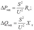
where S – load power;
U – line voltage on the secondary side of the transformer.
For a three-winding transformer or autotransformer, the copper losses are defined as the sum of the power losses of each winding. The total power losses in a two-winding transformer are equal to:
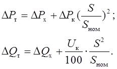
If a substation with total load S has n identical transformers operating in parallel, their equivalent resistances are n times smaller and their conductances are n times larger.
4. Non-deterministic model of electrical load
The non-deterministic nature of the change in electrical load in real electrical networks is due to the presence of a large number of different types of electrical receivers [5]. When transmitting electric power through a section of the electric network, power losses occur, which in general case are not a deterministic value. The paper solves the problem of statistical modeling of power losses on the section of the electric network at non-deterministic load power.
We consider a probabilistic model of electric load, which is defined as a system of random correlated quantities of active P and reactive Q powers [6-7], subject to the normal distribution law. For the system of random variables (P , Q) the characteristics are the mean values of Рc, Qc, standard deviations σP, σQ and correlation coefficient rPQ, (Fig.2). The network parameters are treated as deterministic quantities. The Monte Carlo method is used for statistical modeling [8].

Fig. 2 – System of random correlated values of active and reactive power at different values of correlation coefficient (animation: 16 frames; 33.7 Kb)
5. Measures to reduce power losses
Power and energy losses reach significant values and are one of the main facts affecting the efficiency of networks. Their magnitude is regulated by the regulations of regulatory authorities in networks with voltage up to 35 kV and in networks with voltage of 35 kV and above.
The majority of power losses (60 - 70%) occur in 6 - 10 kV networks [9]. Therefore, the measures listed below apply to networks of these voltages and to electric consumers:
- application of a higher voltage step (10 kV instead of 6 kV);
- increasing the voltage level in the network by applying voltage regulation devices;
- regulation of active and reactive power flows in individual network links;
- the use of rational consumer power supply schemes that allow for more economical loading of power lines and transformers;
- rationalization of power supply facilities of enterprises - improvement of cosφ, correct choice of power and loading of electric motors.
6. Calculation of energy losses
During the transmission of electric power, a part of it is consumed for heating, creation of electromagnetic fields and other effects. This consumption is commonly referred to as losses. In the electric power industry, the term "losses" has a specific meaning. Whereas in other industries losses are related to product defects, electricity losses are a technological expense of electricity transmission.
The amount of power loss depends on the nature of the load change during the time period under consideration. For example, in a power line operating with a constant load, the loss of electricity over time t is calculated as follows:

where ΔP ‒ total losses of active power in the resistance and conductivity of power lines.
If the load varies, power losses can be calculated in various ways. Depending on the mathematical model used, the methods are divided into two groups:
- determined;
- probabilistic-statistical.
The most accurate of the deterministic methods is the method of calculating power losses based on the load schedule for each consumer.
Suppose that the customer's load in a year varied according to the following schedule (Fig.3). There are formulas
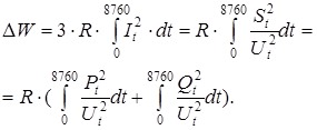
The integral is actually the area bounded by the current squared graph. Thus, active power losses are proportional to the area of the quadratic annual load schedule.

Fig. 3 – Consumer load schedule
7. The task of calculating modes. Basic assumptions
The task of mode calculation is to determine the parameters of the mode, which include [10]:
- values of currents in network elements;
- values of voltages in the network nodes;
- power values at the beginning and end of the network element;
- values of power and energy losses.
Calculation of these values is necessary for equipment selection, power quality assurance, and optimisation of grid operation modes. The initial data for mode calculation are:
- electrical connection diagram and its parameters - values of resistances and conductivities of its elements;
- power of loads or their power schedules;
- values of voltages at individual points of the network.
Theoretically, the network can be calculated using methods known from the discipline of theoretical foundations of electrical engineering, based on Kirchhoff's laws. However, their direct application is difficult for two reasons:
- a large number of elements in a real network;
- the specifics of the initial data assignment.
The specifics of the initial data setting are as follows - the power of loads and the voltage at the power supply source are specified. In order to build a picture of the flow distribution, i.e. to find the power values at the end and beginning of each element, it is necessary to calculate the power losses. For their calculation it is necessary to know the current in each element. Its value can be calculated when the voltage at the load busbars is known. And it is unknown at the beginning of the calculation. Therefore, it is impossible to apply Kirchhoff's laws directly to obtain an unambiguous solution.
The main method of calculating the modes of electric networks is the method of successive approximations - iterative method. It consists in setting the first approximation of voltages in nodes (zero iteration) at the beginning of the calculation. Usually the assumption that the voltages in all nodes of the circuit are equal to each other and equal to the nominal value of the network is taken as the zero iteration. Using the assumed voltage value and the given consumer power, the values of the mode parameters, including the voltage values in the nodes of the network, can be calculated. These voltage values will be the second approximation (first iteration). The calculation is repeated until the results of subsequent approximations do not differ from each other with a given accuracy.
Most often 1-2 iterations are sufficient. However, if the mode optimisation problems related to power losses are solved, many iterations are needed.
The possibility of a small number of iterations has led to the emergence of methods that are not rigorous but give acceptable results. Such methods are:
- method for calculating the mode at a given voltage at the end of the transmission line;
- method for calculating the mode at a given voltage at the beginning of the transmission line (at the power source).
The following assumptions are made when calculating networks up to and including 35 kV:
- does not take into account the charging power of transmission lines;
- inductive resistance of cable transmission lines is not taken into account;
- power losses in transformer steel are not taken into account. No-load losses in transformer are only taken into account when calculating active power and power losses in the entire network;
- power losses are not taken into account when calculating power flows, i.e. the power at the beginning of the section is equal to the power at the end of the section;
- the transverse component of voltage drop is not taken into account. This means that the phase shift of the voltage between the nodes of the circuit is not taken into account;
- the voltage loss calculation is based on the nominal voltage and not on the actual voltage at the nodes of the network.
8. Power balance in the power system
The transmission of electricity through power lines by electromagnetic waves is carried out at a speed close to the speed of light, i.e. almost instantly. This leads to the fact that the production, distribution and consumption of electricity occurs simultaneously [11]. Therefore, at any given time in the steady-state mode, the systems must generate power equal to the power of consumers and the power losses in the system elements. In other words, the power system must have a balance of output and power consumption:
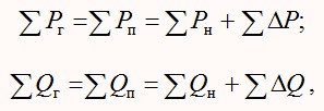
Active power losses include power losses in overhead and cable power lines, electromagnetic devices, and system mode control devices.
Total reactive power losses are the algebraic sum of power losses in the resistances and conductivities of overhead and cable power lines, transformers, magnetization and scattering power of electromagnetic devices.
With the same composition of loads, the active and reactive power consumed by the system is a function of the frequency and voltage on the consumer buses. The power balance in the system corresponds to certain specific values of frequency and voltage.
A quantitative assessment of the change in the values included in the balance equation can be performed based on the static characteristics of the load (consumers) Pп и Qп.
From the analysis of the power balance in the power system, it follows that in order to regulate the voltage, it is necessary to influence, first of all, the reactive power, and to regulate the frequency, it is necessary to change the active power.
Therefore, the task of regulating the regime includes the following subsections:
- regulation of active power and frequency in the power system;
- regulation of reactive power and voltage in the power system.
This separation is also explained by the physics of the electricity production process. The current frequency is determined by the rotational speed of synchronous machines, which depends on the ratio of the torque and braking moments on the shaft of the turbine-generator unit. To change their ratio, it is necessary to change (increase or decrease) the intake of energy into the turbine. At the same time, the generation of active power, the rotation frequency of synchronous machines and, as a result, the frequency of current in the power system changes.
In addition, it should be borne in mind that
- There are more stringent requirements for frequency changes in the power system than for voltage changes;
- The optimal work schedule is set for each power plant;
- In addition to generators, there are additional sources of reactive power that can be installed in places closer to consumers.
List of sources
- Идельчик, В. И. Электрические системы и сети: Учебник для вузов. / В.И. Идельчик. ‒ М.: Энергоатомиздат, 1989, — 592 с: ил.
- Глазунов, А.А. Электрические сети и системы 4-е изд., перераб. и доп. / А.А. Глазунов. ‒ М.: Госэнергоиздат, 1960. ‒ 368 с.
- Лыкин, А.В. Электрические системы и сети : учебник / А.В. Лыкин. — Новосибирск : Новосибирский государственный технический университет, 2017. — 363 c.
- Потери энергии в электрических сетях и установках : учебное пособие / Г. В. Маслакова, А. А. Митрофанов, Е. А. Чащин, Ю. А. Шурыгин. — Липецк : Липецкий государственный технический университет, ЭБС АСВ, 2018. — 79 c.
- Электрические нагрузки промышленных предприятий / С.Д. Волобринский, Г.М. Каялов, П.Н. Клейн, Б.С. Мешель. − Л.: Энергия, 1971. − 264 с.
- Вентцель, Е.С. Теория вероятностей / Е.С. Вентцель. – М. : Наука, 1965. – 576 с.
- Аркашов, Н.С. Теория вероятностей и случайные процессы : учебное пособие / Н. С. Аркашов, А. П. Ковалевский. — 2-е изд. — Новосибирск : Новосибирский государственный технический университет, 2017. — 238 c.
- Метод статистических испытаний (метод Монте-Карло) / Н. П. Бусленко, Д. И. Голенко, И. М. Соболь и др.; под ред. Ю. А. Шрейдера. – М.: Физматгиз, 1962. – 331 с.
- Лыкин, А.В. Распределительные электрические сети : учебное пособие / А.В. Лыкин. — Новосибирск : Новосибирский государственный технический университет, 2018. — 115 c.
- Лыков, Ю.Ф. Расчеты систем электроснабжения : сборник задач и упражнений / Лыков Ю.Ф. — Самара : Самарский государственный технический университет, ЭБС АСВ, 2018. — 54 c.
- Стрельников, Н. А. Энергосбережение : учебное пособие / Н. А. Стрельников. — Новосибирск : Новосибирский государственный технический университет, 2019. — 72 c.