
Abstract on the topic of graduation work
- Introduction
- 1. Overview of mobile robots
- 2. Description of the research prototype
- 2.1 Description of the operating principle and device of the mecanum wheel
- 2.2 Circuit diagram and its description
- 3. Development of a system for remote control of the device
- Conclusions
- Sources
Introduction
Robots are versatile automata for reproducing human motor and intellectual functions. One of their important classes are manipulation robots. The practical purpose of creating robots is to transfer to them those activities that are labor-intensive, heavy, monotonous, harmful to health and life for humans. These are, first of all, auxiliary production operations (loading and unloading of plants, machines, automata); basic production operations (welding, painting, cutting, assembly, etc.); work in so-called extreme conditions (underwater, in space, in radioactive and poisonous environments).
Robots are used for complex automation of production, increasing labor productivity, improving product quality. Industrial robots are distinguished from traditional means of automation by their versatility, the possibility of their rapid changeover, which makes it possible to create on the basis of universal equipment robotic technological complexes, flexible automated production. As a result of the development of robotics, mankind has the opportunity to solve fundamentally new scientific and production problems.
In contrast to stationary robots, most mobile robots are characterized by their size and mobility. For a mobile robot to work productively and correctly. A mobile robot needs a good control system. The following is a discussion of the types of robots, the requirements for their control systems, and the design of one.
1. Overview of mobile robots
A mobile robot is an automated mechanism that can move around in its environment.
Automation began in the automotive industry during World War II (1946), and the origin of the term itself comes from D.S. Harder, an engineering manager at Ford Motor Company. At first, the term was used to describe the increased presence of automated devices in production lines and purely manufacturing contexts. Automation is now widely used in many industries where computerized actions and feedback loops can replace human intervention in the workplace. Over time, development in this area has become increasingly dependent on advanced computer technology and advances in technological capabilities.
In their current form, most industrial robots have mechanical arms with the ability to perform anthropomorphic actions. Advances in computer miniaturization, mathematical control theory, and improved sensor technology have had a major impact on the feedback control systems that drive robotics. The first industrial robot performed spot welding and injection molding at a General Motors plant in New Jersey, USA, in 1962. Soon robotic arms exploded in the large-scale manufacturing industry, and several new companies emerged, including Kuka in 1973, Nachi in 1969, Fanuc in 1974, Yaskawa in 1977, ASEA in 1977, and several others. By 1980, it was estimated that a new major robotics company was entering the market every month.
Mobile robots are now experiencing a similar expansion as they become much more reliable in industrial settings. Even if a mobile robot makes mistakes, this will ultimately be less frequent than human-caused errors.
In today's world, robots are gaining a huge role in many areas of human activity. They are used in medicine, the service sector, the military, and rescue operations. The main task of robots is to replace humans in monotonous and dangerous operations. In the early days of robotics, these were uncomplicated or cyclically repetitive procedures, but the development of robotics is on the path of increasing the range of operations that robots must perform without human intervention.
Modern robots perform a variety of functions. For example, the Da Vinci medical robot can perform complex operations; the Spirit, Opportunity, and Curiosity rovers have proven that robots can do a good job of exploring Mars; various robots are used by FSB units to prevent terrorist attacks; and robots are also used by Rosatom's rescue teams to deal with emergencies. However, even the most advanced models of robots are not capable of performing the entire range of work independently. This indicates the complexity of solving the problems of autonomous control of robots. Therefore, most mobile systems work under the control of a human operator
Диапазон применения робототехники чрезвычайно широк:
– robots are replacing humans in manufacturing. Full automation of many processes reduces human involvement in production to making important decisions and troubleshooting equipment malfunctions;
– robots are used in space and ocean exploration;
– robots are used to perform the most complex brain and heart surgeries. Robotic prosthetic limbs and some internal organs have been developed;
– military equipment is becoming smarter and more independent - movement control, situational control, aiming and target acquisition are performed by the machine, while humans are left with tactical tasks and maintenance.
Because there is no way to measure motor current in the mobile robot prototype under development, we decided to use a single-loop speed control system with a PID controller.
The input of the speed controller is an algebraic summation of the speed reference signal UZ.C and feedback signals. The constant negative speed negative feedback is used to organize the speed control loop. Negative current negative feedback, due to the presence of the current cutoff of the TO, comes into operation only when the motor current exceeds a certain maximum value Iots, reducing the input signal of the RS.
The speed sensor is assumed to be inertia-free.
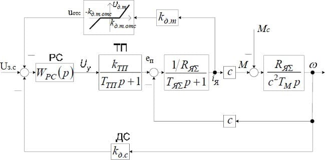
Figure 1 – Structural diagram of a single-circuit speed control system of DC Motor
During normal system operation, the motor armature current is within acceptable limits and the negative current feedback does not apply.
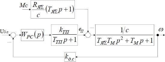
Figure 2 – Simplified structural diagram of a single-circuit speed control system
Proportional-integral-differential (PID) controller is a device in the control loop with feedback. It is used in automatic control systems to form a control signal in order to obtain the required accuracy and quality of the transient process. PID regulator generates a control signal, which is the sum of three summands, the first of which is proportional to the difference between the input signal and the feedback signal (mismatch signal), the second is the integral of the mismatch signal, the third is the derivative of the mismatch signal.
The proportional component produces an output signal that counteracts the deviation of the regulated variable from the setpoint observed at a given time. The larger it is, the greater the deviation. If the input signal is equal to the setpoint, the output signal is zero.
But with a proportional controller alone, the regulated variable is never stabilized at the set point. There is a so-called static error, which is equal to the deviation of the regulated variable that provides an output signal that stabilizes the output variable at this value.
The greater the proportionality factor between the input and output signal (gain), the smaller the static error, but if the gain is too high, if there is a delay (lag), the system may start to oscillate, and if the gain is increased further, the system may become unstable.
The integrating component is proportional to the integral over time of the deviation of the controlled variable. It is used to eliminate static error. It allows the controller to account for the static error over time.
If the system does not experience external disturbances, after some time the regulated quantity will stabilize at the set point, the signal of the proportional component will be zero, and the output signal will be fully provided by the integrating component. However, the integrating component can also lead to auto oscillations if its coefficient is not chosen correctly.
The differentiating component is proportional to the rate of change of the regulated quantity deviation and is designed to counteract deviations from the target value that are predicted to occur in the future. Deviations can be caused by external disturbances or by the lag of the regulator's effect on the system.
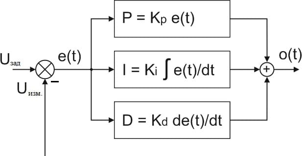
Figure 3 – PID controller structure diagram
2.Description of the research prototype
2.1 Description of the operating principle and device of the mecanum wheel
The following equipment is used in the prototype mobile robot:
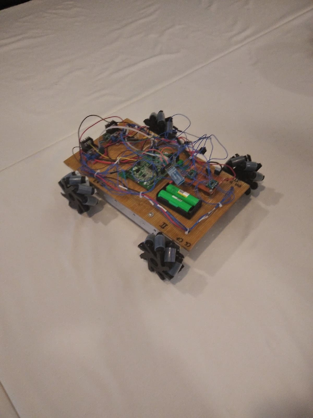
Figure 4 – Mobile robot prototype
Four DC motors equipped with L2523-60002 incremental type encoders.
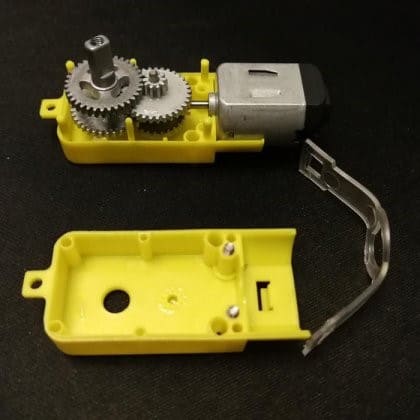
Figure 6 – External view of a DC motor with encoder
An encoder is a device that is designed to convert the angle of rotation of a shaft (the object being measured) into electrical impulses that can be used to determine: the angle of rotation, the speed of rotation, the direction of rotation, and the current position relative to the starting point.
The prototype mobile robot uses incremental encoders. At its core, an incremental encoder is a counter that counts the pulses that occur as the shaft rotates. The encoder is either mounted directly on the shaft or connected via a flexible adapter coupling.
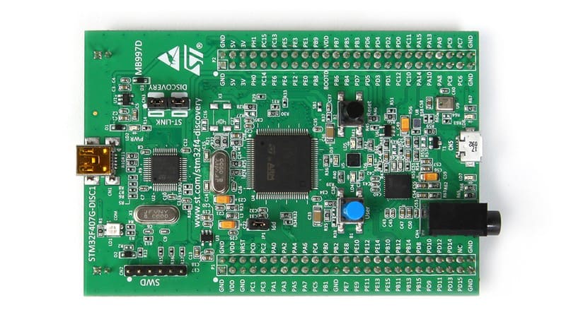
Figure 7 – Microcontroller STM32F407 – Discovery
The STM32F4 Discovery board is designed to familiarize you with the capabilities of a 32-bit microcontroller based on the ARM architecture, as well as to realize your own devices and applications using the board hardware. ARM architecture is an instruction system and a family of descriptions and ready topologies of 32-bit and 64-bit microprocessor/microcontroller cores.
The mecanum wheel is an omnidirectional wheel design for a land vehicle to travel in any direction. It is sometimes called the Swedish wheel or the Ilon wheel after its inventor, Bengt Erland Ilon (1923-2008), who conceived the concept while working as an engineer for the Swedish company Mecanum AB and patented it in the United States on November 13, 1972
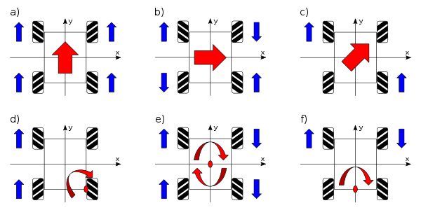
Figure 8 – Motion diagram of a mobile robot based on mecanum wheels
a)Straight forward motion, b) Side-to-side motion, c) Diagonal motion, d) Bending motion, e) Rotation, f) Rotation around the center point of a single axis
The typical Mecanum design is a four-wheeled configuration, as demonstrated by one of the URANUS omnidirectional mobile robots or a wheelchair with Mecanum wheels, with alternating left and right casters, with the axes of the top of the wheel parallel to the diagonal of the vehicle frame (and hence perpendicular to the diagonal when the bottom of the wheel is in contact with the ground). Thus, each wheel will generate a thrust approximately parallel to the corresponding frame diagonal. By varying the rotational speed and direction of each wheel, the summation of the force vectors from each of the wheels will create both linear motions and/or rotations of the vehicle, allowing it to maneuver with minimal space requirements.
For example:
– Moving all four wheels in the same direction at the same speed will result in a forward/backward motion because the longitudinal force vectors add up, but the transverse vectors cancel each other out;
– Running (all at the same speed) both wheels on one side in the same direction and on the other side in the opposite direction will result in a stationary rotation of the vehicle as the transverse vectors cancel, but the longitudinal vectors combine to generate torque around the center vertical axis of the vehicle;
– Running (all at the same speed) diagonal wheels in one direction while the other diagonal in the opposite direction will result in lateral motion because the transverse vectors add up but the longitudinal vectors cancel.
– The combination of differential wheel motions will allow the car to move in almost any direction with any rotation.
2.2 Circuit diagram and its description
The circuit diagram contains the following elements: STM32F407 microcontroller - Discovery, two L298N motor drivers, two AD8544 comparators, UART module, Bluetoothv3.0 module, DC motor with encoder on the shaft, 3.3V voltage stabilizer, 3.3/1.5V voltage divider.
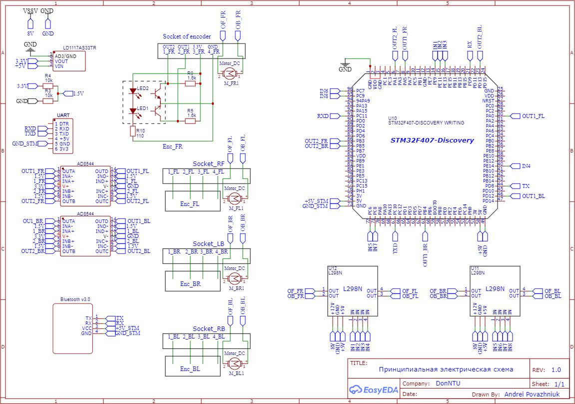
Figure 9 – Schematic diagram of a mobile robot on mecanum wheels
The 8V power supply to the circuit is supplied to the drivers from two Li-ion batteries of the US18650GS type connected in series. From the L298N driver through the built-in 5V voltage regulator, power is supplied to the STM32F407 - Discovery and to a 3.3V voltage regulator, and from it to a 3.3/1.5V voltage divider. The STM32F4 board supplies power to the UART and Bluetooth modules.
Control is done via an app on a mobile device or via the UART module. The signals from the mobile device are transmitted via Bluetooth to the STM32F4 board, which controls the L298N drivers.
After processing the received data from the modules, the microcontroller supplies PWM signals to the pins of the L298N driver and the drives start to rotate according to the task.
3.Development of a system for remote control of the device
MIT App Inventor is a cloud-based visual app development environment for the Android OS platform that does not require knowledge of a programming language, just basic algorithmic knowledge. To work in MIT App Inventor you need to have a Google or Google Apps account, and building programs is done in visual mode using blocks of program code.
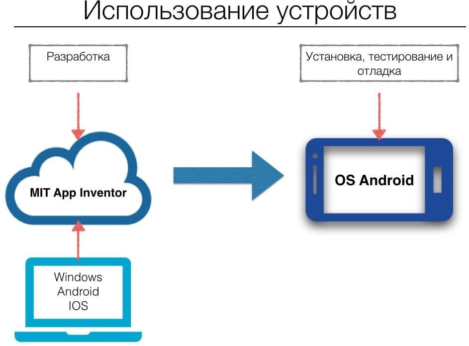
Figure 10 – Application development scheme
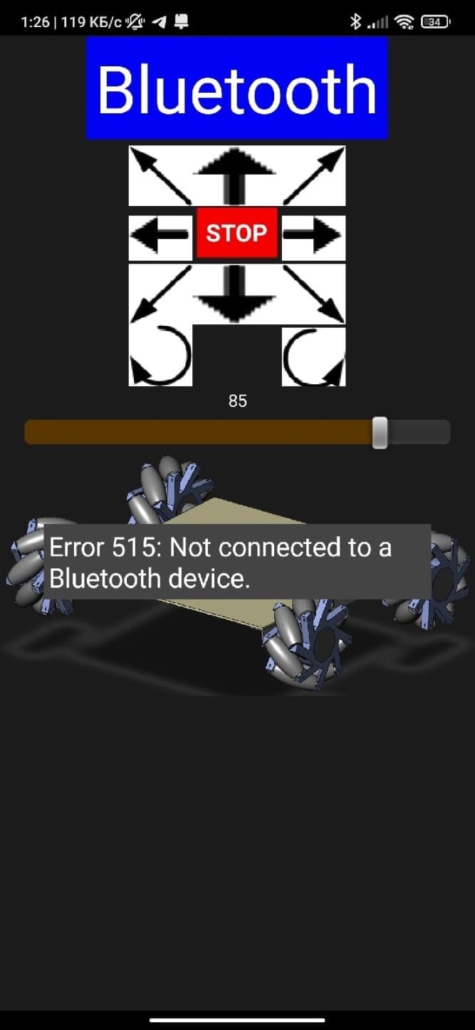
Figure 11 – View of the finished application
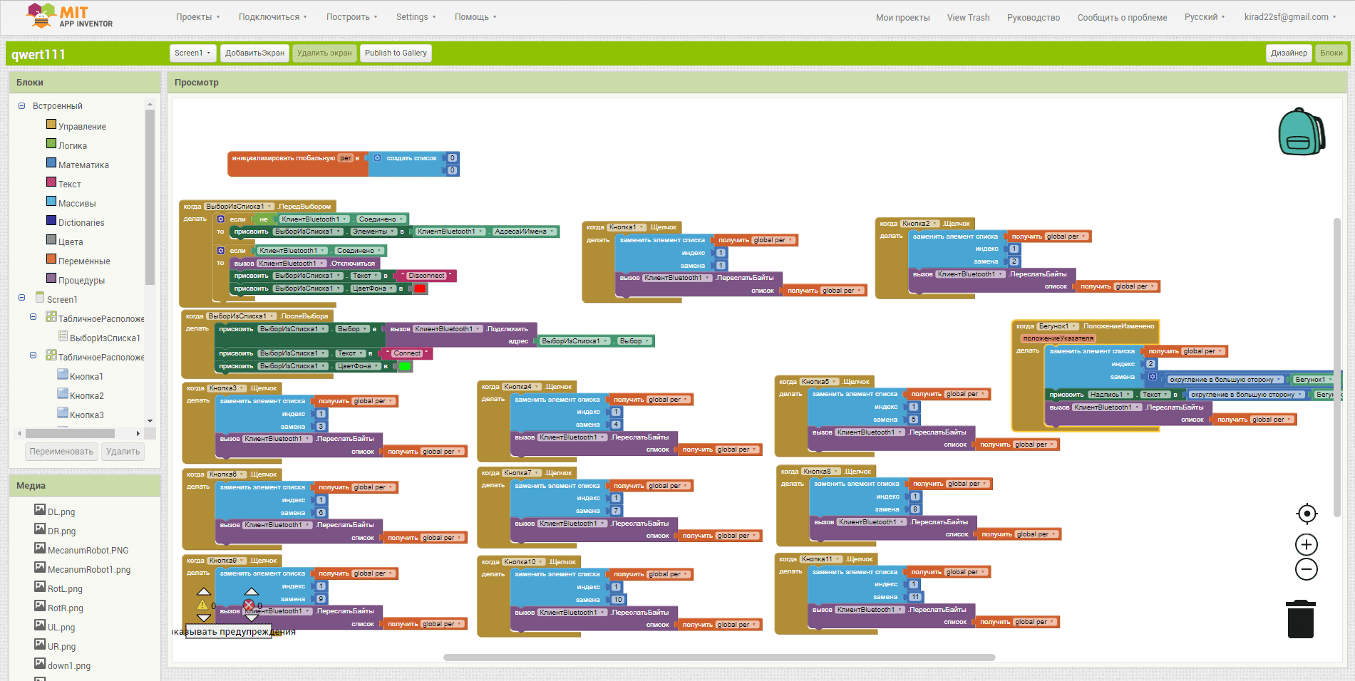
Figure 12 – Block view of the robot control program
Pressing the "Bluetooth" button, in the opened menu we need to select the desired Bluetooth receiver, after which the program will make a check and replace the inscription "Bluetooth" with "Connect" (green background) or "Disconnect" (red background) and then you can control the robot.
The principle of the Runner robot is very similar to the control buttons discussed earlier. When you change the position of the slider, it replaces the array element and rounds it up and adds 100, for easy representation as a percentage. The speed percentage is also displayed on the smartphone screen from 0 to 100.
Conclusions
To accomplish this task, we modernized the control system based on the STM32F407 microcontroller and developed a smartphone application. Four DC motors are used to provide the robot's movement, and a speed control loop is configured.
Sources
1. Мобильные роботы: что это такое, виды и классификация [Electronic resource]. - Access mode: https://vektorus.ru/blog/mobilnye-roboty.html
2. Классификация мобильных роботов [Electronic resource]. – Access mode:https://helpiks.org/6-11883.html
3. Что такое робототехника? [Electronic resource]. – Access mode:https://mining-cryptocurrency.ru/robototekhnika/
4. Крауиньш Д.П. Автоматизированный электропривод: учебное пособие / Д.П. Крауиньш; Томский политехнический университет. Томск: Изд. Томского политехнического университета, Томск, 2011. – 99 с.
5. L298N Datasheet [Electronic resource]. – Access mode:https://www.alldatasheet.com/datasheet-pdf/pdf/22440/STMICROELECTRONICS/L298N.html
6. Теория и практика Н-моста [Electronic resource]. – Access mode:http://www.mcmanis.com/chuck/robotics/tutorial/h-bridge/
7. Аккумуляторная батарея 18650 [Electronic resource]. – Access mode:https://batareykaa.ru/akkumulyatornaya-batareya-18650